Sun Microsystems SPARCstation 5 Service Manual
Hide thumbs
Also See for SPARCstation 5:
- User manual ,
- Service manual (210 pages) ,
- Product notes (20 pages)

Related Manuals for Sun Microsystems SPARCstation 5


Summary of Contents for Sun Microsystems SPARCstation 5
- Page 1 SPARCstation 5 Service Manual A Sun Microsystems, Inc. Business 901 San Antonio Road Palo Alto, , CA 94303-4900 Part No: 801-6396-11 Revision A, August 1994...
- Page 2 USA 650 960-1300 fax 650 969-9131...
- Page 3 SPARCstation 5 Service Manual Part No: 801-6396-11 Revision A, August 1994...
- Page 4 52.227-14(g)(2)(6/87) and FAR 52.227-19(6/87), or DFAR 252.227-7015(b)(6/95) and DFAR 227.7202-3(a). Sun, Sun Microsystems, the Sun logo, and Solaris are trademarks or registered trademarks of Sun Microsystems, Inc. in the United States and in other countries. All SPARC trademarks are used under license and are trademarks or registered trademarks of SPARC International, Inc.
-
Page 5: Table Of Contents
Preface x Product Description 1 Standard Features 1 Subassemblies, Boards, and Components 2 Interior View 2 Rear View of SPARCstation 5 System 3 Internal Options 4 External Options 5 Troubleshooting Overview 7 Factory-Defined Boot Mode 7 After Power Is Switched On 10... - Page 6 Powering Off the System 43 When the System Is Working Normally 43 When the System Does Not Respond Normally Powering On the System 46 Internal Access 47 Removing the Cover 47 SPARCstation 5 Service Manual ♦ Revision A, August 1994...
- Page 7 Attaching the Wrist Strap 49 Replacing the Cover 50 Major Subassemblies 53 Power Supply 53 Removing the Power Supply 53 Replacing the Power Supply 55 Power LED 57 Removing the Power LED 57 Replacing the Power LED 58 Internal Speaker 60 Removing the Internal Speaker 60 Replacing the Internal Speaker 63 SCSI Backplane 64...
- Page 8 Replacing an S24 Frame Buffer Card 110 DSIMMs 113 Removing a DSIMM 113 Replacing a DSIMM 115 System Board 117 Removing the System Board 117 Replacing the System Board 120 Setting Jumpers 122 SPARCstation 5 Service Manual ♦ Revision A, August 1994...
- Page 9 Replacement Parts List 131 System Specifications 133 Physical Specifications 133 Input Power Requirements 134 Environmental Requirements 134 SPARCstation 5 Input/Output Connectors 137 SCSI Connector (External) 137 Parallel Port Micro-D Connector 139 Attachment Unit Interface (AUI) Micro-D Connector 140 Twisted-Pair Ethernet Connector 141...
-
Page 10: Watch-Clock 151
151 watch-net, watch-aui, watch-tpe, and watch-net-all 152 probe-scsi, probe-scsi-all 154 module-info 154 test-memory 155 Returning to the Old-Style Sunmon Compatibility Mode Prompt 155 Glossary 157 Index 161 SPARCstation 5 Service Manual ♦ Revision A, August 1994... -
Page 11: Preface
This book is divided into seven parts. A table, at the beginning of each part, lists the chapters, sections, and page numbers. 4 Part 1, “System Information,” provides an overview of the SPARCstation 5 standard features, internal options, and external options. -
Page 12: Related Documentation
Read Chapter 6 in Owner’s Guide. AaBbCc123 words to be emphasized These are called class options. You must be root to do this. Code samples are included in boxes and may display the following: SPARCstation 5 Service Manual ♦ Revision A, August 1994... - Page 13 Typographic Conventions TABLE P–1 (continued) Typeface or Symbol Meaning Example UNIX C shell prompt system% UNIX Bourne and Korn shell prompt Superuser prompt, all shells...
- Page 14 SPARCstation 5 Service Manual ♦ Revision A, August 1994 xiii...
-
Page 15: Product Description
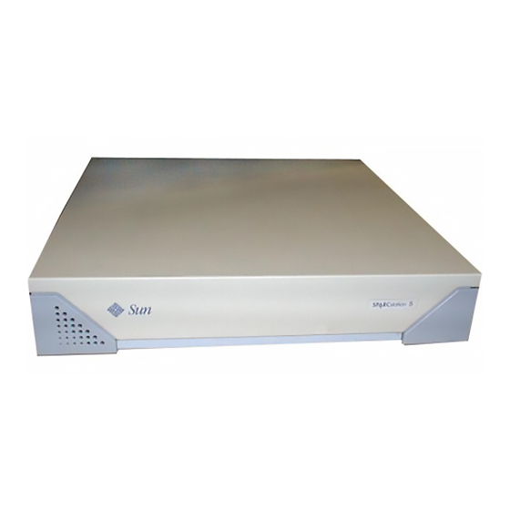
4 Internal CD-ROM drive It also accommodates up to 256 Mbytes of memory using dynamic single in-line memory modules (DSIMMs). The system has four audio ports on the back panel and includes an internal speaker. Figure 1–1 shows a typical SPARCstation 5 system. -
Page 16: Subassemblies, Boards, And Components
Figure 1–1 Basic SPARCstation 5 System Subassemblies, Boards, and Components The SPARCstation 5 system unit accommodates the following subassemblies, boards, and components: 4 System board 4 DSIMMs (up to 8) 4 S24 graphics card 4 SBus cards (up to 3) 4 Hard disk drives, 3.5-inch, 88.0-mm, single-connector (up to 2) -
Page 17: Rear View Of Sparcstation 5 System
Figure 1–2 Interior View of SPARCstation 5 System Rear View of SPARCstation 5 System Figure 1–3 shows the rear view of the system. Product Description... -
Page 18: Internal Options
Quantity Comments S24 card Provides accelerated 24-bit color graphics on the system AFX Bus. SBus cards Up to 3 System board provides up to three SBus slots for additional system functionality. SPARCstation 5 Service Manual ♦ Revision A, August 1994... -
Page 19: External Options
Internal Options TABLE 1–1 (continued) Option Quantity Comments Hard disk 1 or 2 System supports up to two disk drives of varying drives capacities. See Chapter 9,” for more information. CD-ROM drive Internal CD-ROM drive. Diskette drive Internal diskette drive for diskette I/O. DSIMMs Up to 8 System supports up to 256 Mbytes of dynamic single... - Page 20 Requires a minimum of two SCSI controllers if all three trays are used. You cannot have more than seven SCSI devices on each SCSI bus. SPARCstation 5 Service Manual ♦ Revision A, August 1994...
-
Page 21: Troubleshooting Overview
Troubleshooting Overview This chapter describes the factory-defined boot sequence. It also describes the different types of SPARCstation 5 diagnostic firmware and software tools that are available to you for troubleshooting; the chapter explains how the tools are related and when to use them. - Page 22 Figure 2–1 Factory-Defined Boot Sequence—POST Phase Settings and Tests If you need to run extended FORTH Diagnostics to take advantage of more extensive tests, see Appendix D.” SPARCstation 5 Service Manual ♦ Revision A, August 1994...
- Page 23 Figure 2–2 Factory-Defined Boot Sequence—OpenBoot PROM Phase Settings and Tests Troubleshooting Overview...
-
Page 24: After Power Is Switched On
The status of the POST is conveyed by four LEDs on the Sun Type-4, Type-5, and Compact 1 keyboards. The Caps Lock LED blinks to indicate that the tests are in progress. If a failure is detected during low-level POST, one of the other three LEDs will light to indicate the nature of the failure. - Page 25 Table 2–1Table 2–1 contains a list of NVRAM parameters and explains their effect on the power-up sequence. For more detailed information about NVRAM parameters, see the OpenBoot Command Summary. Note - At any point during the high-level OBP execution, you can abort the OBP sequence and access the FORTH Monitor by pressing the Stop and “a”...
-
Page 26: Diagnostic Tools And When To Use Them
Table 2–3 provides a summary of the available diagnostic tools and describes when to use each tool. 1. The boot parameters represented here are default settings. The defaults may be changed by following the procedures listed in the OpenBoot Command Summary. SPARCstation 5 Service Manual ♦ Revision A, August 1994... -
Page 27: Power-On Self-Test
Diagnostic Tools TABLE 2–3 Diagnostic Tool When or Why to Use the Tool Power-On Executes automatically at power-on when Stop-d keys are pressed or Self-Test (POST) when the diag-switch? parameter is set to true. The POST code resides in the boot PROM and is driven by the POK signal from the power supply. -
Page 28: Forth-Based Prom Diagnostics
FORTH-Based PROM Diagnostics For information about how to run the FORTH Diagnostics, see Appendix D.” Table 2–4Table 2–4 lists specific on-board diagnostic tests for SPARCstation 5 systems. Selected FORTH Diagnostic Tests TABLE 2–4 Type of Test Description Preparation When to Use... - Page 29 Selected FORTH Diagnostic Tests TABLE 2–4 (continued) Type of Test Description Preparation When to Use The drive must be spinning Disk drive Tests internal or external test disk before this test is executed or does not SCSI disks that have a test disk0 the test will fail.
-
Page 30: Watch-Net
Connect the system to the When an watch- packets on all Ethernet network via the desired SBus card net-all interfaces installed in the Ethernet port. network system, one at a time. controller card is installed. SPARCstation 5 Service Manual ♦ Revision A, August 1994... -
Page 31: Probe-Scsi
SCSI host adapter host adapter cards). controller is defective. power-off Powers off the system. You must have a Sun Type-5 To power off keyboard in order to use this the system command. with a Sun Type-5 keyboard. -
Page 32: Forth Monitor
SunDiagnostic Executive if all POSTs pass, but your system still has a problem. For information about POST, see “Power-On Self-Test (POST)” on page 19.” The SunDiagnostic Executive is described in the SunDiagnostic Executive User’s Guide for the SPARCstations. SPARCstation 5 Service Manual ♦ Revision A, August 1994... -
Page 33: Power-On Self-Test (Post)
Power-On Self-Test (POST) This chapter describes the Power-On Self-Test (POST) for Normal, Full, and Abbreviated modes, available with your SPARCstation 5 system. The Power-On Self-Test (POST) diagnostics reside in the OpenBoot PROM located on the system board. There are two POST modes: Normal and Diagnostic. - Page 34 Figure 3–1 Arrangement of Sun Type-5 Keyboard Diagnostic LEDs Figure 3–2 Sun Type-4 Keyboard SPARCstation 5 Service Manual ♦ Revision A, August 1994...
- Page 35 POSTs are running. The keyboard LED diagnostics feature described here applies only to a SPARCstation 5 system with a Sun Type-4, Type-5, or Compact 1 keyboard connected to its keyboard port. The LED diagnostics do not apply if a...
-
Page 36: Normal Mode
SBus modules. Full Diagnostic Mode runs if one of these conditions is met: 4 You press and hold the Stop-d keys while you turn on the power. 4 You set the diag-switch? NVRAM parameter to true in the OpenBoot PROM. SPARCstation 5 Service Manual ♦ Revision A, August 1994... -
Page 37: Abbreviated Diagnostic Mode
TTY or tip window. Setting Up a tip Connection to Another System You can use the serial port on your SPARCstation 5 system to connect to another Sun workstation (either the same type of SPARC“ system or a different type of Sun workstation or server system). -
Page 38: Tests The Post Runs
3. In a Shell Tool window on the Sun workstation, type tip hardwire. (Some commands will not work properly in a Command Tool window.) The system will reply connected. hostname% tip hardwire connected The Shell Tool window is now a tip window directed to the Sun workstation serial port. -
Page 39: Post Error Messages
FPU Double-precision Tests FPU SP Invalid CEXC Test FPU SP Overflow CEXC Test FPU SP Divide-by-0 CEXC Test FPU SP Inexact CEXC Test FPU SP Trap Priority > Test FPU SP Trap Priority < Test FPU DP Invalid CEXC Test FPU DP Overflow CEXC Test FPU DP Divide-by-0 CEXC Test FPU DP Inexact CEXC Test... - Page 40 If the Caps Lock key fails to flash on and off after you have pressed and held the Stop-d keys when you power on the system, POST failed. See “System Board Test” on page 31,” for troubleshooting information. SPARCstation 5 Service Manual ♦ Revision A, August 1994...
-
Page 41: Troubleshooting Procedures
CHAPTER Troubleshooting Procedures This chapter describes how to troubleshoot SPARCstation 5 system problems. Each problem is described, and a set of procedures is provided as a solution to the problem. Table 4–1 describes commonly encountered problems, and tips for solving them. -
Page 42: No Video Output On The System Monitor
If the power cord and video cable connection are good and there is still no video output, reseat the video card for the monitor. 4. If the monitor power supply is internally fused, check the fuse. The fuse could be blown. SPARCstation 5 Service Manual ♦ Revision A, August 1994... -
Page 43: Power-On Does Not Succeed
The LEDs on the keyboard should briefly light. You should hear a tone from the keyboard. If you have a Sun Type-5 keyboard, there is a Standby power key which you may also press to see if the system can be powered on or not. Only try the Standby power key if the rear switch fails to turn on the system. - Page 44 2 B rown -12V Black Ground 3 R ed Black Ground 4 R ed Black Ground 5 R ed Black Ground 6 R ed Black Ground 7 R ed Green AC Outlet SPARCstation 5 Service Manual ♦ Revision A, August 1994...
-
Page 45: System Board Test
Power Supply Connector Pin Assignments TABLE 4–2 (continued) Description Color Color Description 8 R ed Purple 9 G rey Power off Yellow Power on All volts are direct current. System Board Test 1. Connect a terminal to serial port A or use a tip connection to another workstation to receive additional POST failure information. -
Page 46: Disk Drive Errors
To check whether the built-in SCSI controller is defective, test the drive response to the probe-scsi command. To test additional SCSI host adapters added to the system, use the probe-scsi-all command. Refer to “module-info” on page 154.” 1. At the ok prompt, type probe-scsi SPARCstation 5 Service Manual ♦ Revision A, August 1994... -
Page 47: Determining Faulty Dsimm Locations
See the following example. ok probe-scsi Target 1 Unit 0 Disk CONNER CP30548 SUN0535AEBX93081QTT Target 3 Unit 0 Disk SEAGATE ST3610N SUN0535881200054301 a. If the disk drive responds and a message is displayed, the system SCSI controller has successfully probed the devices. This indicates that the system board is working correctly. - Page 48 0800 0000 through 09FF FFFF J0401 0A00 0000 through 0BFF FFFF 1. Each memory slot can contain one DSIMM up to 32 megabytes in size. Slot 0 must have a DSIMM present. SPARCstation 5 Service Manual ♦ Revision A, August 1994...
- Page 49 Physical Memory Address Ranges for Slots 0 Through 7 TABLE 4–4 (continued) Slot SIMM # Physical Memory Address Ranges J0402 0C00 0000 through 0DFF FFFF J0403 0E00 0000 through 0FFF FFFF Troubleshooting Procedures...
- Page 50 SPARCstation 5 Service Manual ♦ Revision A, August 1994...
-
Page 51: Safety And Tools Requirements
CHAPTER Safety and Tools Requirements This chapter describes standards, safety procedures, and precautions you should follow whenever you need to replace or remove assemblies or subassemblies from your system. Safety Requirements For your protection, observe the following safety requirements: 4 Follow all cautions, warnings, and instructions marked on the equipment. 4 Ensure that the voltage and frequency rating of the power outlet matches the electrical rating labels on the system. -
Page 52: Symbols
The heat sink can be hot enough to cause personal injury. heat sink Symbols The following symbols mean: Caution - This equipment contains lethal voltages. Accidental contact can result in serious injury or death. SPARCstation 5 Service Manual ♦ Revision A, August 1994... -
Page 53: System Precautions
Procedures contained in this document must be performed by trained maintenance ®® providers. Only people who have been trained at the Sun Microsystems training facilities (or at Sun Microsystems affiliates) and have been certified as required by local and national laws are considered qualified. Safety and Tools Requirements... -
Page 54: Tools Required
4 When removing a board, card, or module from an antistatic bag, lay it on an antistatic surface such as a Sun ESD mat, an antistatic bag, or a disposable antistatic mat. 4 Do not place the boards, cards, or modules on an unprotected surface. Use a cushioned antistatic mat or antistatic bag. - Page 55 4 Do not use an oscilloscope or VOM (volt-ohmmeter) probe on the components. The soldered pins are easily damaged or shorted by the probe point. 4 Transport boards, cards, or modules in an antistatic bag. 4 Always wear an antistatic wrist strap connected to a metal surface on the chassis when working on system components and parts.
- Page 56 SPARCstation 5 Service Manual ♦ Revision A, August 1994...
-
Page 57: Power On And Off
CHAPTER Power On and Off This chapter explains steps to perform before removing a customer replaceable unit (CRU). Powering Off the System Before you begin any removal or replacement procedure, you must halt the system in an orderly manner. The procedure to use depends on whether your system is working normally or not, as described in the next sections. -
Page 58: When The System Does Not Respond Normally
2. Press Stop-a (or Break). ®® If you use a Wyse WY-50 , VT-100 , or compatible terminal as the console with your SPARCstation 5 system unit, press Break instead of Stop-a. SPARCstation 5 Service Manual ♦ Revision A, August 1994... - Page 59 Note - If the system does not respond to the mouse and keyboard, pressing Stop-a will not be effective. You may have to turn the power off, wait at least 10 seconds, and turn the power on again. Then try pressing Stop-a once more. 3.
-
Page 60: Powering On The System
This pause prevents possible damage to power supply components in your system unit. To turn on power to the SPARCstation 5 system: 1. If your system uses external drive units, turn on the power to these units first, starting with the unit that is furthest electrically from the system unit. -
Page 61: Internal Access
CHAPTER Internal Access This chapter describes how to access the subassemblies inside the system unit, and how to close the system unit after you have finished. Removing the Cover Caution - The AC power cord should remain attached between the system unit and an AC wall outlet. - Page 62 Remove the lock block and put it aside (see Figure 7–1). Figure 7–1 Removing the Rear Panel Cover Screws 4. Lift the cover free of the chassis as shown in Figure 7–2. SPARCstation 5 Service Manual ♦ Revision A, August 1994...
-
Page 63: Attaching The Wrist Strap
Figure 7–2 Removing the Cover 5. Attach a wrist strap to your wrist and to the metal casing of the power supply. See “Attaching the Wrist Strap” on page 49. Caution - When you are finished servicing parts inside the system unit, be sure to close the system unit before turning on the power. -
Page 64: Replacing The Cover
2. Align the cover hinge tabs with the tab slots on the bottom front of the system chassis. Carefully lower the cover, making sure the hinge hooks remain inside their respective slots. SPARCstation 5 Service Manual ♦ Revision A, August 1994... - Page 65 Figure 7–4 Replacing the Cover 3. Replace the lock block on the rear panel. Tighten the Phillips-head screw that secures the lock block to the cover. See Figure 7–5. 4. Tighten the captive Phillips-head screw in the upper-right corner of the rear panel.
- Page 66 See Figure 7–5. Caution - Do not use a power driver to tighten captive screws. Do not overtighten captive screws. Figure 7–5 Securing the System Unit Cover SPARCstation 5 Service Manual ♦ Revision A, August 1994...
-
Page 67: Major Subassemblies
AC power switch before disconnecting the external power cord from the rear panel. The SPARCstation 5 power supply “remembers” the state it was in when the power cord was detached, and it will automatically return to that state when the power cord is reconnected. - Page 68 5. On the rear panel, loosen the captive screw(s) securing the power supply to the chassis. Some models have two captive screws, others have one. See Figure 8–1. SPARCstation 5 Service Manual ♦ Revision A, August 1994...
-
Page 69: Replacing The Power Supply
Figure 8–1 Removing the Power Supply 6. Disconnect the power supply connector from the system board. See Figure 8–1. 7. Slide the power supply toward the chassis front to free it from the chassis mounts. See Figure 8–1. 8. Lift the power supply out of the chassis and disconnect the DC power harness from the keyed connector on the rear of the power supply. - Page 70 5. Tighten the captive screw(s) to secure the power supply to the rear of the chassis. See Figure 8–1. Caution - Do not use a power driver to tighten a captive screw. Do not overtighten a captive screw. SPARCstation 5 Service Manual ♦ Revision A, August 1994...
-
Page 71: Power Led
6. Plug the power supply connector into the system board. See Figure 8–1. 7. Remove the wrist strap from your wrist and then from the power supply. 8. Replace the cover. See “Replacing the Cover” on page 50. 9. Plug in the power cord to the system unit and the wall outlet. 10. -
Page 72: Replacing The Power Led
1. Position the replacement LED/cable assembly so that the LED contacts the LED light pipe. Then press the cable between the LED tabs to secure it in place. See Figure 8–4. SPARCstation 5 Service Manual ♦ Revision A, August 1994... - Page 73 Figure 8–4 Positioning the LED Cable 2. Route the cable behind the diskette drive bracket and connect it to the in-line connector of the speaker/LED cable. See Figure 8–4. 3. Reinstall the CD-ROM drive (if necessary). See “Replacing the CD-ROM Drive” on page 72. 4.
-
Page 74: Internal Speaker
5. Use the screwdriver to push on the tab inside the slot. At the same time, pull slightly on the speaker cover to disengage the tab from the chassis. 6. Repeat 5 for the second slot. SPARCstation 5 Service Manual ♦ Revision A, August 1994... - Page 75 Figure 8–5 Removing the Speaker Cover 7. Use the screwdriver to deflect the third tab, behind the top corner of the speaker cover, and remove the speaker cover. Caution - Use care when working near or handling the speaker to avoid damaging the speaker surface.
- Page 76 9. Hold the speaker in one hand and disconnect the two fast-on connectors from the speaker terminals on the back of the speaker. See Figure 8–7. 10. Set the speaker aside. SPARCstation 5 Service Manual ♦ Revision A, August 1994...
-
Page 77: Replacing The Internal Speaker
Figure 8–7 Speaker Connections Replacing the Internal Speaker Caution - Do not touch the black inner surface of the speaker. Handle the speaker only by the metal frame to avoid damage. 1. Pull the speaker end of the speaker/LED cable through the speaker opening in the chassis wall. -
Page 78: Scsi Backplane
3. Remove the hard disk drive(s). See “Removing a Hard Disk Drive” on page 68. 4. Disconnect the DC power harness and SCSI data cable from the SCSI backplane. See Figure 8–8. SPARCstation 5 Service Manual ♦ Revision A, August 1994... - Page 79 Figure 8–8 Removing the SCSI Backplane 5. Remove the two Phillips-head screws that secure the SCSI backplane to its plastic mounting bracket. Remove the SCSI backplane from the system unit chassis. See Figure 8–8. Major Subassemblies...
-
Page 80: Replacing The Scsi Backplane
6. Remove the wrist strap from your wrist and then from the power supply. 7. Replace the cover. See “Replacing the Cover” on page 50. 8. Power on the system. See “Powering On the System” on page 46. SPARCstation 5 Service Manual ♦ Revision A, August 1994... -
Page 81: Storage Devices
4 Remove disk drive to be replaced 4 Install new disk drive The SPARCstation 5 system accommodates 535-Mbyte and 1.05-Gbyte hard disk drives. Both drives have a single connector that connects to the SCSI backplane in the system unit chassis. A specially designed handle, fastened to the drive, speeds drive removal and installation. -
Page 82: Removing A Hard Disk Drive
SCSI address 1 on installation. SCSI termination for internal drives is provided automatically by the SCSI backplane. Caution - Once a hard drive has been installed in the SPARCstation 5 system, do not change the position of that drive. SPARCstation 5 Service Manual ♦ Revision A, August 1994... -
Page 83: Replacing A Hard Disk Drive
4. A latch is located at the rear of the drive. Press the plastic latch to release the drive handle. 5. Lift the drive handle to its vertical position. When lifted, the drive bracket acts as a lever to disconnect the drive from the chassis connector on the SCSI backplane. - Page 84 SCSI bus. However, if a drive is installed later in the upper bay, its automatic address will conflict with that of the external peripheral. SPARCstation 5 Service Manual ♦ Revision A, August 1994...
-
Page 85: Cd-Rom Drive
Figure 9–3 Replacing a Disk Drive 5. Repeat Steps 3 and 4 to reinstall the top disk drive (if necessary). 6. Detach the wrist strap and replace the cover. See Chapter 7. 7. Power on the system. See “Powering On the System” on page 46. CD-ROM Drive Removing the CD-ROM Drive 1. -
Page 86: Replacing The Cd-Rom Drive
5. Lift the drive out of the chassis and place it on an antistatic surface. Figure 9–4 Removing the CD-ROM Drive Replacing the CD-ROM Drive 1. Remove the replacement CD-ROM drive from its antistatic bag. SPARCstation 5 Service Manual ♦ Revision A, August 1994... - Page 87 Jumpers should be present for ID4, ID2, and Term power; all other jumpers should be removed. Figure 9–5 Jumper Settings for SPARCstation 5 CD-ROM Drive 3. Install the drive as shown in Figure 9–6. The CD-ROM drive sits on the shelf above the diskette drive. Push the drive toward the center of the unit so that the grommets lock into place.
-
Page 88: Diskette Drive
4 Remove the CD-ROM drive (if necessary) 4 Remove the diskette drive 4 Set the diskette drive switch to the 0 position on the replacement drive 4 Install the diskette drive SPARCstation 5 Service Manual ♦ Revision A, August 1994... -
Page 89: Removing The Diskette Drive
The diskette drive is not a SCSI device. Some of the other drives in your system are SCSI devices—such as the CD-ROM drive and the hard disk drives. The diskette drive connects to an 8-bit internal bus in the SPARCstation 5 system. Figure 9–7... - Page 90 You may need to use a screwdriver for leverage. Use the screwdriver to push on the drive grommets as shown in Figure 9–9. Do not push on the drive’s front bezel. SPARCstation 5 Service Manual ♦ Revision A, August 1994...
- Page 91 Figure 9–9 Disengaging the Diskette Drive 5. Lift the diskette drive out of the drive bracket. Holding the drive in one hand, detach the diskette data and DC power cables from the drive with your other hand. See Figure 9–10 Storage Devices...
-
Page 92: Replacing The Diskette Drive
Install the grommets in the lower set of holes as shown in Figure 9–11. 2. Set the diskette drive switch to position 0. If your diskette drive does not have a switch, skip this step. See Figure 9–11. SPARCstation 5 Service Manual ♦ Revision A, August 1994... - Page 93 Figure 9–11 Diskette Drive Switch and Grommets 3. Holding the diskette drive in one hand, lower it far enough into the chassis to connect the cables. Attach the diskette data and DC power cables to the drive. See Figure 9–12. 4.
- Page 94 If you need to install the CD-ROM drive, see “Replacing the CD-ROM Drive” on page 72. 6. Detach the wrist strap and replace the cover. See Chapter 7. 7. Power on the system. See “Powering On the System” on page 46. SPARCstation 5 Service Manual ♦ Revision A, August 1994...
-
Page 95: Internal Scsi Data Cable
Internal SCSI Data Cable Removing the Internal SCSI Cable 1. Shut down and power off the system. See “Powering Off the System” on page 43. 2. Detach all external cables from the rear panel except the power cord. 3. Remove the cover and attach a wrist strap. See Chapter 7. - Page 96 6. Pull the board out of the back of the chassis until it clears the plastic card guide. Place the board on an antistatic surface. See Figure 9–15. Figure 9–15 Removing the System Board SPARCstation 5 Service Manual ♦ Revision A, August 1994...
-
Page 97: Replacing The Internal Scsi Data Cable
7. Remove the CD-ROM drive (if present). See “Removing the CD-ROM Drive” on page 71. 8. Free the SCSI data cable from the metal cable clips on the chassis floor and from the plastic cable clips on the card guide. See Figure 9–14. - Page 98 5. Insert the front edge of the system board into the card guide. Lift the rear of the board slightly and slide it along the card guide until it is fully inserted. See Figure 9–17. SPARCstation 5 Service Manual ♦ Revision A, August 1994...
- Page 99 Figure 9–17 Replacing the System Board 6. Reconnect the DC power, SCSI data, diskette data, speaker/LED, and CD-ROM audio cables to the system board. See Figure 9–16. 7. Reinstall the SBus card (if necessary). See “Replacing an SBus Card” on page 105. 8.
-
Page 100: Dc Power Harness
See “Powering Off the System” on page 43. 2. Detach all external cables from the rear panel, including the power cord. 3. Remove the cover and attach a wrist strap. See Chapter 7. SPARCstation 5 Service Manual ♦ Revision A, August 1994... - Page 101 4. Unplug the DC power, SCSI data, diskette data, speaker/LED, and CD-ROM audio cables from the system board (see Figure 9–19). You may need to remove an SBus card to access the audio connector. See “Removing an SBus Card” on page 102. Figure 9–19 System Board Cable Connections 5.
- Page 102 Place the board on an antistatic surface. See Figure 9–21. Figure 9–21 Removing the System Board 7. Remove the CD-ROM drive (if present). See “Removing the CD-ROM Drive” on page 71. SPARCstation 5 Service Manual ♦ Revision A, August 1994...
- Page 103 8. Disconnect the DC power harness from the diskette drive. 9. Free the SCSI data cable from the metal cable clips on the chassis floor and from the card guide plastic cable clips. See Figure 9–22. 10. Disconnect the SCSI data cable from the SCSI backplane. See Figure 9–22.
-
Page 104: Replacing The Dc Power Harness
8. Insert the front edge of the system board into the card guide. Lift the rear of the board slightly and slide it along the card guide until it is fully inserted. See Figure 9–23. SPARCstation 5 Service Manual ♦ Revision A, August 1994... - Page 105 Figure 9–23 Replacing the System Board 9. Reconnect the DC power, SCSI data, diskette data, speaker/LED, and CD-ROM audio cables to the system board. See Figure 9–22. 10. Reinstall the SBus card (if necessary). See “Replacing an SBus Card” on page 105. 11.
-
Page 106: Diskette Data Cable
See “Powering Off the System” on page 43. 2. Remove the cover and attach a wrist strap. See Chapter 7. 3. Remove the CD-ROM drive (if present). See “Removing the CD-ROM Drive” on page 71. SPARCstation 5 Service Manual ♦ Revision A, August 1994... -
Page 107: Replacing The Diskette Data Cable
4. Remove the diskette drive. See “Removing the Diskette Drive” on page 75. 5. Unplug the diskette data cable from the system board. See Figure 9–25. 6. Carefully note how the diskette data cable is routed, and remove it from the system chassis. -
Page 108: Cd-Rom Audio Cable
Figure 9–26 shows where the audio cable connects to the CD-ROM drive. Figure 9–26 Audio Connector on the CD-ROM Drive 4. Disconnect the CD-ROM audio cable from its connector on the system board. SPARCstation 5 Service Manual ♦ Revision A, August 1994... -
Page 109: Replacing The Cd-Rom Audio Cable
See Figure 9–27. Figure 9–27 CD-ROM Audio Connector on the System Board 5. Carefully note how the CD-ROM audio cable is routed, and remove it from the system chassis. Replacing the CD-ROM Audio Cable 1. Route the replacement cable in the same manner as the defective cable that you just removed. - Page 110 See Figure 9–27. 4. Detach the wrist strap and replace the cover. See Chapter 7. 5. Power on the system. See “Powering On the System” on page 46. SPARCstation 5 Service Manual ♦ Revision A, August 1994...
-
Page 111: System Board Overview
Use an antistatic mat when working with the system board. An antistatic mat contains the amount of cushioning needed to protect the underside components, to prevent board flexing, and to provide antistatic protection. Part numbers for antistatic mats from Sun are listed in Chapter 12. Handling System Boards and Assemblies... -
Page 112: System Board Layout
Protect yourself and the equipment by observing the safety precautions described in Chapter 5. System Board Layout Figure 10–1 shows the major components on the system board. Figure 10–1 SPARCstation 5 System Board SPARCstation 5 Service Manual ♦ Revision A, August 1994... -
Page 113: Replaceable System Board Components
Replaceable System Board Components The following are the system board replaceable components: 4 DSIMMs 4 S24 card 4 SBus cards 4 NVRAM 4 System board Chapter 11 describes how to remove and replace these components. System Board Overview... - Page 114 SPARCstation 5 Service Manual ♦ Revision A, August 1994...
-
Page 115: System Board And Component Replacement
CHAPTER System Board and Component Replacement This chapter describes how to remove, replace, and configure the SPARCstation 5 system board and its replaceable parts. SBus Cards The system board has three locations for SBus cards (see Figure 11–1). Figure 11–1... -
Page 116: Removing An Sbus Card
3. Push the card retainers back from the edge of the SBus card. See Figure 11–2. Figure 11–2 Opening the SBus Card Retainers 4. Remove the SBus card extractor from the replacement SBus card: SPARCstation 5 Service Manual ♦ Revision A, August 1994... - Page 117 a. Bend one leg of the extractor slightly to the outside until the hook clears the hole in the SBus card. See Figure 11–3. b. Remove the other side of the extractor, which should come out easily without bending it. Place the replacement SBus card on an antistatic surface.
- Page 118 6. Hold both ends of the card extractor. Pull upward slowly until the connector is detached from the slot. See Figure 11–5 and Figure 11–6. Figure 11–5 Removing a Single-Width SBus Card SPARCstation 5 Service Manual ♦ Revision A, August 1994...
-
Page 119: Replacing An Sbus Card
Figure 11–6 Removing a Double-Width SBus Card 7. Remove the card extractor from the SBus card: a. Bend one leg of the extractor slightly to the outside until the hook clears the hole in the SBus card. See Figure 11–5. b. - Page 120 Press the corners of the card to push the connector into the socket. See Figure 11–7. Caution - Do not force the card. Align the card connector and socket properly or you may damage the pins on the card. SPARCstation 5 Service Manual ♦ Revision A, August 1994...
-
Page 121: S24 Frame Buffer Card
Figure 11–8 Closing the SBus Card Retainers 5. Push the card retainers forward to clamp down the SBus card. See Figure 11–8. 6. Detach the wrist strap and replace the cover. See Chapter 7. 7. Power on the system. See “Powering On the System” on page 46. S24 Frame Buffer Card The S24 frame buffer card plugs into the AFX Bus slot shown in Figure 11–9. -
Page 122: Removing An S24 Frame Buffer Card
4. Locate the defective S24 card and push the card retainers back from the edge of the card. See Figure 11–10. 5. Insert the legs of the card extractor into the holes on the faulty S24 card. See Figure 11–10. SPARCstation 5 Service Manual ♦ Revision A, August 1994... - Page 123 Figure 11–10 Opening the Card Retainers 6. Hold both ends of the card extractor. Pull upward slowly and evenly until the connector is detached from the slot. See Figure 11–11. System Board and Component Replacement...
-
Page 124: Replacing An S24 Frame Buffer Card
Replacing an S24 Frame Buffer Card 1. Locate the AFX Bus slot on the system board. See Figure 11–10. 2. Push back the two card retainers on the AFX Bus slot (if necessary). See Figure 11–10. SPARCstation 5 Service Manual ♦ Revision A, August 1994... - Page 125 Note - Before installing the S24 card, inspect the AFX Bus slot for bent pins. Do not install the S24 card if a pin in the slot is bent. If necessary, straighten bent pins with needlenose pliers. 3. Holding the replacement S24 card at an angle to the rear panel, insert the tabs on the card backplate into the corresponding slots on the rear panel.
- Page 126 5. Push the card retainers forward to clamp down the S24 card. See Figure 11–13. 6. Detach the wrist strap and replace the cover. See Chapter 7. 7. Power on the system. See “Powering On the System” on page 46. SPARCstation 5 Service Manual ♦ Revision A, August 1994...
-
Page 127: Dsimms
DSIMMs. Caution - DSIMMs installed in your system must have been specifically designed to operate in it. Do not remove DSIMMs from a different Sun system and install them in a SPARCstation 5 system. Caution - A DSIMM is made of delicate electronic components that are extremely sensitive to static electricity. - Page 128 DSIMM Slot Locations on the System Board 5. To eject the faulty DSIMM, press down on the ejection levers on both sides of the DSIMM connector (see Figure 11–15). Figure 11–15 Ejecting a DSIMM SPARCstation 5 Service Manual ♦ Revision A, August 1994...
-
Page 129: Replacing A Dsimm
6. Holding the DSIMM by its edges, remove it from the slot and place it on an antistatic surface. Replacing a DSIMM 1. Carefully remove the new DSIMM from its protective packaging and place it on an antistatic surface. The bag that the DSIMM is packed in makes a good antistatic surface. 2. - Page 130 4. Place your thumbs as shown in Figure 11–17 and push the DSIMM firmly into its connector. 5. To lock the DSIMM in place, push both ejector levers into the upright position. SPARCstation 5 Service Manual ♦ Revision A, August 1994...
-
Page 131: System Board
Figure 11–17 Installing a DSIMM 6. Detach the wrist strap and replace the cover. See Chapter 7. 7. Power on the system. See “Powering On the System” on page 46. 8. Watch for the system banner to verify that the new memory is recognized by the system. - Page 132 7. Unplug the DC power, SCSI data, diskette data, speaker/LED, and CD-ROM audio cables from the system board (See Figure 11–18). You may need to remove an SBus card to access the audio connector. See “Removing an SBus Card” on page 102. SPARCstation 5 Service Manual ♦ Revision A, August 1994...
- Page 133 Figure 11–18 System Board Cable Connections 8. Loosen the two captive Phillips-head screws that secure the system board to the rear of the chassis. See Figure 11–19. Figure 11–19 System Board Captive Screws System Board and Component Replacement...
-
Page 134: Replacing The System Board
Lift the rear panel of the board slightly to make sure that the “foot” on the underside of the board doesn’t catch the metal edge of the chassis. c. Slide the board along the card guide until it is fully inserted. SPARCstation 5 Service Manual ♦ Revision A, August 1994... - Page 135 Figure 11–21 Installing the System Board 2. Tighten the two captive Phillips-head screws that secure the board to the rear of the chassis. Do not overtighten these screws. See Figure 11–22. Figure 11–22 System Board Captive Screws System Board and Component Replacement...
-
Page 136: Setting Jumpers
2. Remove the cover and attach a wrist strap. See Chapter 7. 3. Use needlenose pliers to move both serial port jumpers from position B to position A. See Figure 11–23. SPARCstation 5 Service Manual ♦ Revision A, August 1994... - Page 137 Figure 11–23 Setting the Serial Port Jumpers System Board and Component Replacement...
-
Page 138: Nvram
5. Hold the NVRAM chip carrier on both ends and lift it straight up to remove it. Gently wiggle the chip carrier as necessary. 6. Put the NVRAM in its chip carrier on an antistatic surface. SPARCstation 5 Service Manual ♦ Revision A, August 1994... -
Page 139: Replacing The Nvram Chip
Replacing the NVRAM Chip 1. Locate the NVRAM location on the system board. See Figure 11–24. 2. Carefully align the pins and insert the NVRAM chip in the socket; make certain that the notches on the socket and chip are aligned properly. The carrier is keyed so that the NVRAM can be installed only one way. - Page 140 SPARCstation 5 Service Manual ♦ Revision A, August 1994...
-
Page 141: Illustrated Parts Breakdown
This chapter provides an illustrated parts breakdown (IPB) of the major parts that comprise the system, and a list of customer replaceable units (CRUs) and their part numbers. Illustrations of Selected CRUs Figure 12–1 through Figure 12–4 illustrate selected CRUs for the SPARCstation 5 system. - Page 142 Figure 12–1 Selected CRUs—System Unit SPARCstation 5 Service Manual ♦ Revision A, August 1994...
- Page 143 Figure 12–2 Standard External Cables Illustrated Parts Breakdown...
- Page 144 Figure 12–3 Optional External Cables Figure 12–4 Microphone and Cable SPARCstation 5 Service Manual ♦ Revision A, August 1994...
-
Page 145: Replacement Parts List
Note - Although the part numbers are correct as of the publication date of this document, they are subject to change. Consult your authorized Sun sales representative or service provider to confirm part numbers before you order new or replacement parts. - Page 146 28 SunMicrophone II 370-1678 Part Number List—Miscellaneous Items TABLE 12–2 Description Item Sun Part No. 29 Wrist Strap 250-1007 30 Antistatic Mat with Sun Logo 250-1088 31 Disposable Antistatic Mat 330-1145 SPARCstation 5 Service Manual ♦ Revision A, August 1994...
-
Page 147: System Specifications
APPENDIX System Specifications This appendix contains system specifications, including physical specifications, input power requirements, and environmental requirements. Physical Specifications Table A–1 lists the physical specifications for the system unit, keyboard, and optical mouse. Physical Specifications TABLE A–1 Height Width Depth Net Weight Component inches (mm) -
Page 148: Input Power Requirements
0 C ˚ to 40 C ˚ (32 F ˚ to 104 F ˚ ) at 20%–70% Relative Humidity (RH), noncondensing—IEC 68-2-1, 68-2-2 Humidity 5% to 95% RH, noncondensing—IEC 68-2-2, 68-2-3 SPARCstation 5 Service Manual ♦ Revision A, August 1994... - Page 149 Environmental Requirements TABLE A–3 (continued) Operating Environment: Altitude range 0 to 3000 meters (0 to 9840 feet), 10 C ˚ to 40 C ˚ (50 F ˚ 104 ˚ F)—IEC 68-2-40, 68-2-41 Vibration 0.25 gravity (g) peak, 5–500 Hz, 3 perpendicular axes—...
- Page 150 SPARCstation 5 Service Manual ♦ Revision A, August 1994...
-
Page 151: Sparcstation 5 Input/Output Connectors
APPENDIX SPARCstation 5 Input/Output Connectors This appendix contains pinouts and illustrations of the SPARCstation 5 system input/output (I/O) connectors. The following connectors are described. 4 “SCSI Connector (External)” on page 137 4 “Parallel Port Micro-D Connector” on page 139 4 “Attachment Unit Interface (AUI) Micro-D Connector” on page 140 4 “Twisted-Pair Ethernet Connector”... - Page 152 49 Request 14 Ground 32 Data 6 50 Direction 15 Ground 33 Data 7 16 Ground 34 Parity 17 Ground 35 Ground 18 Ground 36 Ground 1. All signals are active low. SPARCstation 5 Service Manual ♦ Revision A, August 1994...
-
Page 153: Parallel Port Micro-D Connector
Pinout for Parallel Port Micro-D Connector TABLE B–2 Description Description Strobe_out_l Auto_feed_out_l Data[0] Errpr_in_l Data[1] Init_out_l Data[2] Select_in_l Data[3] Ground Data[4] Ground Data[5] Ground Data[6] Ground Data[7] Ground Ack_out_l Ground Busy_out_l Ground Pe_in Ground Select_out Ground SPARCstation 5 Input/Output Connectors... -
Page 154: Attachment Unit Interface (Aui) Micro-D Connector
Attachment Unit Interface (AUI) Micro-D Connector Pinout for Attachment Unit Interface (AUI) Micro-D Connector TABLE B–3 Description Description Transmit - Transmit + Receive + Receive - Collision - Collision + Power Ground Ground Ground Ground SPARCstation 5 Service Manual ♦ Revision A, August 1994... -
Page 155: Twisted-Pair Ethernet Connector
Twisted-Pair Ethernet Connector Pinout for Twisted-Pair Ethernet Connector TABLE B–4 Description Description Transmit Data + Transmit Data - Receive Data - Receive Data + Presence detect Presence detect Serial Connector Ports A and B Figure B–5 Serial Connector SPARCstation 5 Input/Output Connectors... -
Page 156: Keyboard/Mouse Connector
Data Terminal Ready (DTR) 8 D ata Carrier Detect (DCD) 9 N /C 10 N/C 11 N/C Transmit Clock OUT (TRxC) 12 N/C 13 N/C Keyboard/Mouse Connector Figure B–6 Keyboard/Mouse Connector SPARCstation 5 Service Manual ♦ Revision A, August 1994... -
Page 157: Audio Ports
Note - All signals are standard TTL levels. The +5V supply is fuse-protected. Audio Ports The SPARCstation 5 audio ports are shown in Figure B–7. Figure B–7 SPARCstation 5 Audio Ports Table B–7 describes the signals for the audio ports. -
Page 158: Headphone Connector
Audio Line-in Connector Figure B–10 Audio Line-in Connector This connector is used to connect external stereophonic sound sources such as a compact disc player or cassette tape player to the system. SPARCstation 5 Service Manual ♦ Revision A, August 1994... -
Page 159: Microphone Connector
II (or other suitable microphone) to the system. Note - The SPARCstation 5 microphone port accepts stereophonic input; however, the SunMicrophone II is a monophonic device. Note also that the older SunMicrophone is not compatible with the SPARCstation 5 system. - Page 160 13W3 Video Connector Pin Assignments TABLE B–8 (continued) Function Level Vert Sync Sense <0> Ground Comp Sync Hort Sync Serial Write Sense <1> Sense <2> Ground SPARCstation 5 Service Manual ♦ Revision A, August 1994...
-
Page 161: Scsi Targeting
Assign each SCSI device on the SCSI chain a different SCSI target. Each internal SCSI disk drive present in a SPARCstation 5 system is automatically assigned a SCSI target (see Table C–1 and Table C–2); these targets are only assigned if the device is present. - Page 162 0, 1, 2, 4, 5, 6* External CD-ROM drive 0, 1, 2, 4, 5, 6* Do not assign target 1, 3, or 6 to an external device if it is automatically assigned to an internal device. SPARCstation 5 Service Manual ♦ Revision A, August 1994...
-
Page 163: Forth Diagnostics
APPENDIX FORTH Diagnostics This appendix explains FORTH Diagnostic tests. The following topics and tests are described. 4 “Running the FORTH Diagnostics” on page 149 4 “test <alias name>, test <device path>” on page 151 4 “test-all” on page 151 4 “watch-clock” on page 151 4 “watch-net, watch-aui, watch-tpe, and watch-net-all”... - Page 164 8. Enter help diag at the ok prompt to get a list of tests that comprise the FORTH Diagnostics. 9. Enter the name of the test you wish to execute. The following example shows a list of FORTH Diagnostic tests. SPARCstation 5 Service Manual ♦ Revision A, August 1994...
-
Page 165: Test
ok help diag Category: Diag (diagnostic routines) test device-specifier ( -- ) run selftest method for specified device Examples: test /memory - test memory test /iommu/sbus/ledma/le - test net test floppy - test floppy disk drive test net - test net (device-specifier is an alias) test scsi - test scsi(device-specifier is an alias) watch-clock..., Test -
Page 166: Watch-Net, Watch-Aui, Watch-Tpe, And Watch-Net-All
Type any key to stop......................SPARCstation 5 systems have two types of Ethernet interfaces, 10BaseT (also called twisted-pair Ethernet or TPE) and 10Base5 (also called thick Ethernet or AUI). Only one Ethernet interface may be connected at a time. The system can automatically select which interface is connected and active. - Page 167 You may also control the selection of Ethernet interfaces to monitor by using specific commands. Use watch-tpe to monitor the 10BaseT (TPE) connection or watch-aui to monitor the 10Base5 (thick Ethernet) connection. For example: ok watch-tpe Using TP Ethernet Interface Lance register test -- succeeded Internal loopback test -- succeeded External loopback test -- succeeded...
-
Page 168: Probe-Scsi, Probe-Scsi-All
SBus speed in megahertz. For example: ok module-info CPU FMI,MB86904 Rev. 2.0 : 70.0 Mhz SBus (Divide By 3) : 23.3 Mhz SPARCstation 5 Service Manual ♦ Revision A, August 1994... -
Page 169: Test-Memory
test-memory All of the system main memory will be tested if the system diag-switch? parameter is true. If the diag-switch? parameter is false, this test uses the selftest-#megs parameter in NVRAM to determine how much memory to test. The default for the selftest-#megs parameter is 1, so only 1 megabyte of memory is tested. - Page 170 SPARCstation 5 Service Manual ♦ Revision A, August 1994...
-
Page 171: Glossary
A RMS Amperes root mean square. RMS is often used in power measurements for electronic equipment. attachment unit The port on the SPARCstation 5 system unit where the AUI adapter interface (AUI) port cable is connected. board See printed circuit board. - Page 172 Input/output. A device that inputs data to a computer CPU and receives data from a computer CPU. Examples of I/O devices include keyboards, mice, monitors, and peripherals devices. Integer unit. LANCE Local area network controller for Ethernet. SPARCstation 5 Service Manual ♦ Revision A, August 1994 Glossary-158...
- Page 173 Indicated by the > prompt. From the > prompt, you can boot the system, continue the execution of a halted program, or enter the FORTH Toolkit. Monitor (2) A video display unit that is part of the SPARCstation 5 system. It is not synonymous with terminal. Memory management unit. Nonvolatile RAM.
- Page 174 A terminal may be connected to either of the serial interface ports on the back panel of the SPARCstation 5 system. It is not the same thing as a monitor. Time-of-Day clock. Twisted-pair Ethernet.
-
Page 175: Index
Index Index-161...
Need help?
Do you have a question about the SPARCstation 5 and is the answer not in the manual?
Questions and answers