Sign In
Upload
Manuals
Brands
Sun Microsystems Manuals
Desktop
SPARCstation 5 Model 110
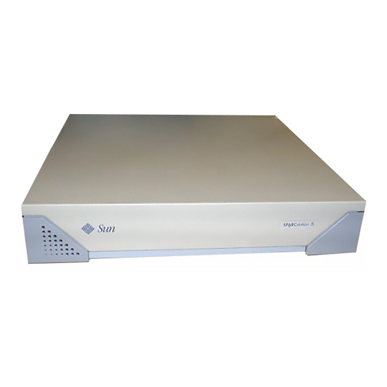
Sun Microsystems SPARCstation 5 Model 110 Manuals
Manuals and User Guides for Sun Microsystems SPARCstation 5 Model 110. We have
1
Sun Microsystems SPARCstation 5 Model 110 manual available for free PDF download: Service Manual
Sun Microsystems SPARCstation 5 Model 110 Service Manual (180 pages)
Brand:
Sun Microsystems
| Category:
Desktop
| Size: 2 MB
Table of Contents
Table of Contents
3
Glossary
16
1 Product Description
19
Standard Features
19
Subassemblies, Boards, and Components
20
Interior View
20
FIGURE 1-1 Basic Sparcstation 5 System
20
Rear View
21
FIGURE 1-2 Interior View of Sparcstation 5 System
21
Internal Options
22
External Options
23
TABLE 1-1 Internal Options
23
TABLE 1-2 Selected External SCSI Peripheral Options
23
2 Troubleshooting Overview
25
Factory-Defined Boot Mode
25
After Power Is Switched on
27
Diagnostic Tools and When to Use Them
31
Power-On Self-Test
32
FORTH-Based PROM Diagnostics
32
TABLE 2-4 Selected FORTH Diagnostic Tests
32
FORTH Monitor
35
System Exercisers
35
3 Power-On Self-Test (POST)
39
Normal Mode
40
Full Diagnostic Mode
40
FIGURE 3-4 Sparcstation System Banner
40
Abbreviated Diagnostic Mode
41
Setting up a Tip Connection to Another System
41
Tests the POST Runs
42
TABLE 3-2 Full Diagnostic Mode Tests
42
POST Error Messages
44
Status Lights (Leds) and Indicators
45
FIGURE 3-5 Location of System Power LED
45
4 Troubleshooting Procedures
47
No Video Output on the System Monitor
48
Power-On Does Not Succeed
48
Power Supply Test
49
FIGURE 4-1 Power Supply Connector
50
TABLE 4-2 Power Supply Connector Pin Assignments
50
System Board Test
51
Disk Drive Errors
52
Verifying the Built-In SCSI Controller
52
TABLE 4-3 Troubleshooting Disk Drive Errors
52
Determining Faulty DSIMM Locations
53
FIGURE 4-2 DSIMM Slot Locations
54
5 Safety and Tools Requirements
55
Safety Requirements
55
Symbols
56
TABLE 5-1 Safety Precautions
56
System Precautions
57
Tools Required
57
Electrostatic Discharge (ESD) Precautions
58
6 Power on and off
59
Powering off the System
59
When the System Is Working Normally
59
When the System Does Not Respond Normally
60
Powering on the System
62
7 Internal Access
63
Removing the Cover
63
FIGURE 7-1 Removing the Rear Panel Cover Screws
64
Attaching the Wrist Strap
65
FIGURE 7-2 Removing the Cover
65
Replacing the Cover
66
FIGURE 7-3 Grounding the Wrist Strap to the Power Supply
66
FIGURE 7-4 Replacing the Cover
67
FIGURE 7-5 Securing the System Unit Cover
68
8 Major Subassemblies
69
Power Supply
69
Removing the Power Supply
69
Replacing the Power Supply
71
FIGURE 8-1 Removing the Power Supply
71
FIGURE 8-2 Connecting the DC Power Harness to the Power Supply
72
Speaker/Led Assembly
73
Removing the Speaker/Led Assembly
73
Replacing the Speaker/Led Cable
74
FIGURE 8-3 Speaker/Power LED Cable Connections
74
FIGURE 8-4 Routing the LED Cable
75
Internal Speaker
76
Removing the Internal Speaker
76
FIGURE 8-5 Removing the Speaker Cover
77
FIGURE 8-6 Removing the Speaker
78
Replacing the Internal Speaker
79
FIGURE 8-7 Speaker Connectors
79
SCSI Backplane
80
Removing the SCSI Backplane
80
FIGURE 8-8 Removing the SCSI Backplane
81
Replacing the SCSI Backplane
82
9 Storage Devices
83
Hard Disk Drive
83
Removing a Hard Disk Drive
84
FIGURE 9-1 Drive Locations
84
Replacing a Hard Disk Drive
85
FIGURE 9-2 Removing a Hard Disk Drive
85
CD-ROM Drive
87
Removing the CD-ROM Drive
87
FIGURE 9-3 Replacing a Hard Disk Drive
87
Replacing the CD-ROM Drive
88
FIGURE 9-4 Removing the CD-ROM Drive
88
FIGURE 9-5 Jumper Settings for the CD-ROM Drive
89
Diskette Drive
90
FIGURE 9-6 Replacing the CD-ROM Drive
90
FIGURE 9-7 Diskette Drive Location
91
Removing the Diskette Drive
91
FIGURE 9-8 Removing the CD-ROM Filler Panel
92
FIGURE 9-9 Disengaging the Diskette Drive
93
FIGURE 9-10 Removing the Diskette Drive
94
Replacing the Diskette Drive
94
FIGURE 9-11 Replacing the Diskette Drive
95
Internal SCSI Data Cable
96
Removing the Internal SCSI Cable
96
FIGURE 9-12 System Board Cable Connections
96
FIGURE 9-13 Rear Panel Captive Screws
97
FIGURE 9-14 Removing the System Board
97
Replacing the Internal SCSI Data Cable
98
FIGURE 9-15 Internal Cable Routing
99
FIGURE 9-16 Replacing the System Board
100
FIGURE 9-17 Backpanel Captive Screws
100
Peripherals DC Power Harness
101
Removing the Peripherals DC Power Harness
101
FIGURE 9-20 Removing the System Board
103
Replacing the Peripherals DC Power Harness
104
FIGURE 9-21 Internal Cable Routing
104
FIGURE 9-22 Replacing the System Board
106
FIGURE 9-23 Rear Panel Captive Screws
106
Diskette Data Cable
107
Removing the Diskette Data Cable
107
Replacing the Diskette Data Cable
108
FIGURE 9-24 System Board Cable Routing
108
CD-ROM Audio Cable
109
Removing the CD-ROM Audio Cable
109
FIGURE 9-25 Audio Cable Connector on the CD-ROM Drive
109
Replacing the CD-ROM Audio Cable
110
FIGURE 9-26 CD-ROM Audio Connector on the System Board
110
10 System Board Overview
113
Damage Prevention
113
Handling System Boards and Assemblies
113
System Board Layout
114
Replaceable System Board Components
115
11 System Board and Component Replacement
117
Sbus Cards
117
Removing an Sbus Card
118
FIGURE 11-1 Sbus Slot Locations
118
FIGURE 11-2 Opening the Sbus Card Retainers
119
FIGURE 11-3 Removing the Extractor from the Sbus Card
120
FIGURE 11-4 Installing the Sbus Card Extractor
121
FIGURE 11-5 Removing a Single-Width Sbus Card
121
Replacing an Sbus Card
122
FIGURE 11-6 Removing a Double-Width Sbus Card
122
FIGURE 11-7 Inserting the Sbus Card
123
S24 Frame Buffer Card
124
FIGURE 11-8 Closing the Sbus Card Retainers
124
FIGURE 11-9 AFX Bus Slot
125
Removing an S24 Frame Buffer Card
125
FIGURE 11-10 Opening the Card Retainers
126
FIGURE 11-11 Removing an S24 Frame Buffer Card
127
Replacing an S24 Frame Buffer Card
127
FIGURE 11-12 Inserting an S24 Frame Buffer Card
128
Dsimms
129
FIGURE 11-13 Closing the Card Retainers
129
Removing a DSIMM
130
FIGURE 11-14 DSIMM Slot Locations on the System Board
131
FIGURE 11-15 Ejecting a DSIMM
131
FIGURE 11-16 Orienting a DSIMM
132
Replacing a DSIMM
132
FIGURE 11-17 Installing a DSIMM
133
System Board
134
Removing the System Board
134
Replacing the System Board
136
FIGURE 11-20 Removing the System Board
136
Setting Jumpers
138
FIGURE 11-23 Setting the Serial Port Jumpers
139
Nvram
140
Removing the NVRAM Chip
140
FIGURE 11-24 Locating the NVRAM
140
Replacing the NVRAM Chip
141
FIGURE 12-1 Selected Crus in the System Unit
143
FIGURE 12-2 Standard External Cables
144
12 Illustrated Parts Breakdown
145
FIGURE 12-3 Optional External Cables
145
FIGURE 12-4 Microphone and Cable
145
Replacement Parts List
146
TABLE 12-1 Part Number List-Customer-Replaceable Units
146
TABLE 12-2 Part Number List-Miscellaneous Items
147
System Specifications
149
Physical Specifications
149
TABLE A-3 Environmental Requirements
149
A.1 Physical Specifications
149
Input Power Requirements
150
Environmental Requirements
150
TABLE A-2 Input Power Requirements and Power Dissipation
150
Input/Output Connectors
153
SCSI Connector (External
153
FIGURE B-1 External SCSI Connector
153
Parallel Port Micro-D Connector
154
FIGURE B-2 Parallel Port Micro-D Connector
154
TABLE B-2 Pinout for Parallel Port Micro-D Connector
154
Attachment Unit Interface (AUI) Micro-D Connector
155
FIGURE B-3 Attachment Unit Interface (AUI) Micro-D Connector
155
TABLE B-3 Pinout for Attachment Unit Interface (AUI) Micro-D Connector
155
Twisted-Pair Ethernet Connector
156
FIGURE B-4 Twisted-Pair Ethernet Connector
156
TABLE B-4 Pinout for Twisted-Pair Ethernet Connector
156
Serial Connector Ports a and B
157
FIGURE B-5 Serial Connector
157
TABLE B-5 Pinout for Serial Connector Ports a and B
157
Keyboard/Mouse Connector
158
FIGURE B-6 Keyboard/Mouse Connector
158
TABLE B-6 Pinout for Keyboard/Mouse Connector
158
Audio Ports
159
Audio Line-Out Connector
159
FIGURE B-7 Audio Ports
159
FIGURE B-8 Headphone Connector
159
FIGURE B-9 Audio Line-Out Connector
159
Headphone Connector
159
TABLE B-7 Signals for the Sparcstation 5 Audio Ports
159
Audio Line-In Connector
160
Microphone Connector
160
13W3 Video Connector
160
FIGURE B-10 Audio Line-In Connector
160
FIGURE B-11 Microphone Connector
160
FIGURE B-12 13W3 Video Connector
161
TABLE B-8 13W3 Video Connector Pin Assignments
161
SCSI Targeting
163
TABLE C-1 SCSI Targeting-Solaris 1.X (Sunos 4.X) Operating Systems
163
TABLE C-2 SCSI Targeting-Solaris 2.X (Sunos 5.X) Operating Systems
164
FORTH Diagnostics
165
Running the FORTH Diagnostics
165
Test <Alias Name>, Test <Device Path
165
D.1.1 Test <Alias Name>, Test <Device Path>
167
Test-All
168
Watch-Clock
168
D.1.6 Module-Info
171
Probe-Scsi, Probe-Scsi-All
171
D.1.7 Test-Memory
172
Advertisement
Advertisement
Related Products
Sun Microsystems MCS 2000 SL
Sun Microsystems SPARCstation 5
Sun Microsystems Ethernet MMF/UTP Adapter
Sun Microsystems Sun SPARC Enterprise M3000
Sun Microsystems Sun SPARC Enterprise M4000
Sun Microsystems Sun SPARC Enterprise M8000
Sun Microsystems Sun SPARC Enterprise M9000
Sun Microsystems Sun SPARC Enterprise M5000
Sun Microsystems Sun SPARC Enterprise M900
Sun Microsystems MEA 1500 SL
Sun Microsystems Categories
Server
Storage
Desktop
Computer Hardware
Adapter
More Sun Microsystems Manuals
Login
Sign In
OR
Sign in with Facebook
Sign in with Google
Upload manual
Upload from disk
Upload from URL