Sun Microsystems SPARCstation 5 Service Manual
Hide thumbs
Also See for SPARCstation 5:
- User manual ,
- Service manual (175 pages) ,
- Product notes (20 pages)

Subscribe to Our Youtube Channel
Related Manuals for Sun Microsystems SPARCstation 5


Summary of Contents for Sun Microsystems SPARCstation 5
- Page 1 Sun SPARCstation 5 service manual PN 408287-053 Revision A A PART OF THE MARQUETTE U N I T Y N E T W O R K...
- Page 2 VAULT, IMPACT.wf, INTELLIMOTION, INTER-LEAD, IQA, LIFEWATCH, MARQUETTE MEDICAL SYSTEMS, MARQUETTE® RESPONDER, MENTOR, MicroSmart, MMS, MRT, MUSE CardioWindow, O2 SENSOR, OMRS, Premium, RAC, SILVERTRACE, SMART-PAC, SMARTLOOK, SOLARVIEW, Spectra-Overview, Trimline, UNITY, and Universal are trademarks of Marquette Medical Systems, Inc. Sun SPARCstation 5 Revision A 6 March 1998 408287-053...
- Page 3 ™ SPARCstation 5 Service Manual Sun Microsystems Computer Company A Sun Microsystems, Inc. Business 2550 Garcia Avenue Mountain View, CA 94043 USA 415 960-1300 fax 415 969-9131 Part No.: 802-7085-10 Revision A November 1996...
- Page 4 Sun, Sun Microsystems, the Sun logo, and Solaris, SunOS, OpenBoot, SunCD, SunCD Plus, and SunDiag are trademarks or registered trademarks of Sun Microsystems, Inc. in the United States and in other countries. All SPARC trademarks are used under license and are trademarks or registered trademarks of SPARC International, Inc.
- Page 5 Contents Preface ..........xvii Part 1 –System Information 1.
- Page 6 5. Safety and Tools Requirements ......5.1 Safety Requirements....... SPARCstation 5 Service Manual—November 1996...
- Page 7 5.2 Symbols ......... 5.3 System Precautions.
- Page 8 9.7.1 Removing the CD-ROM Audio Cable ... 9-29 9.7.2 Replacing the CD-ROM Audio Cable... . 9-30 SPARCstation 5 Service Manual—November 1996...
-
Page 9: Table Of Contents
Part 5 –System Board 10. System Board Overview ....... 10-1 10.1 Damage Prevention . - Page 10 D. FORTH Diagnostics ........D-1 D.1 Running the FORTH Diagnostics ....D-2 viii SPARCstation 5 Service Manual—November 1996...
- Page 11 D.1.1 test <alias name>, test <device path> ... D-4 D.1.2 test-all ........D-4 D.1.3 watch-clock .
- Page 12 SPARCstation 5 Service Manual—November 1996...
- Page 13 Figures Figure 1-1 Basic SPARCstation 5 System ......Figure 1-2 Interior View of SPARCstation 5 System ....
- Page 14 Internal Cable Routing ....... . . 9-19 SPARCstation 5 Service Manual—November 1996...
- Page 15 CD-ROM Audio Connector on the System Board ..9-30 Figure 10-1 SPARCstation 5 System Board......10-3 Figure 11-1 SBus Slot Locations .
- Page 16 13W3 Video Connector ....... . . B-10 Figure D-1 Displaying FORTH Diagnostics ......SPARCstation 5 Service Manual—November 1996...
- Page 17 Tables Table 1-1 Internal Options ........Table 1-2 Selected External SCSI Peripheral Options .
- Page 18 Pinout for Keyboard/Mouse Connector ....Table B-7 Signals for the SPARCstation 5 Audio Ports ....Table B-8 13W3 Video Connector Pin Assignments .
- Page 19 This book is divided into seven parts. A table, at the beginning of each part, lists the chapters, sections, and page numbers. • Part 1, “System Information,” provides an overview of the SPARCstation 5 standard features, internal options, and external options. •...
- Page 20 These are called class options. You must be root to do this. Code samples are included in boxes and may display the following: UNIX C shell prompt system% UNIX Bourne and Korn shell prompt Superuser prompt, all shells xviii SPARCstation 5 Service Manual—November 1996...
- Page 21 System administration manual for the computer system • Operating system documentation Ordering Sun Documents The SunDocs Order Desk is a distribution center for Sun Microsystems technical documents. You can use major credit cards and company purchase orders. You can order documents in the following ways: Country...
- Page 22 SPARCstation 5 Service Manual—November 1996...
- Page 23 Part 1 – System Information Chapter 1 Product Description...
- Page 25 Product Description This chapter presents a brief overview of the major components of the SPARCstation 5 system. Please acquaint yourself with the overview before servicing and maintaining the hardware for this product. Standard Features page 1-1 Internal Options page 1-5...
-
Page 26: Part 5 -System Board
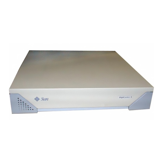
Figure 1-1 Basic SPARCstation 5 System 1.1.1 Subassemblies, Boards, and Components The SPARCstation 5 system unit accommodates the following subassemblies, boards, and components: • System board • DSIMMs (up to 8) • S24 graphics card • SBus cards (up to 3) •... -
Page 27: Figure 1-2 Interior View Of Sparcstation 5 System
1.1.2 Interior View Figure 1-2 shows an interior view of the major subassemblies and the system board for the SPARCstation 5 system. Hard drives CD-ROM drive Diskette drive (stacked) (top unit) (bottom unit) DSIMMs Power AFX Bus slot supply SBus slots... - Page 28 14—Audio, headphone 3—Lock block 9—AUI Ethernet 15—Audio, line-out 4—SBus 10—Twisted-pair Ethernet 16—Audio, line-in 5—SBus or AFX Bus 11—Serial port B 17—Audio, microphone 6—AC power receptacle 12—Serial port A Figure 1-3 Rear View of SPARCstation 5 System SPARCstation 5 Service Manual—November 1996...
-
Page 29: Table 1-1 Internal Options
1.2 Internal Options Table 1-1 lists the internal options. Table 1-1 Internal Options Option Quantity Comments S24 card Provides accelerated 24-bit color graphics on the system AFX Bus. SBus cards Up to 3 System board provides up to three SBus slots for additional system functionality. -
Page 30: Table 1-2 Selected External Scsi Peripheral Options
Holds up to eight disk drives and two or three removable media in the upper tray. Requires a minimum of two SCSI controllers if all three trays are used. You cannot have more than seven SCSI devices on each SCSI bus. SPARCstation 5 Service Manual—November 1996... - Page 31 Part 2 – Troubleshooting Chapter 2 Troubleshooting Overview Chapter 3 Power-On Self-Test (POST) Chapter 4 Troubleshooting Procedures...
- Page 33 Troubleshooting Overview This chapter describes the factory-defined boot sequence. It also describes the different types of SPARCstation 5 diagnostic firmware and software tools that are available to you for troubleshooting; the chapter explains how the tools are related and when to use them.
- Page 34 OpenBoot™ PROM (OBP) firmware. The following sections describe the relationship between the various diagnostic tools, and the role each tool plays during the SPARCstation 5 factory-defined boot sequence. The descriptions in the following sections assume you are using a graphics monitor to view test results.
- Page 35 OpenBoot PROM Phase After POST phase, OpenBoot PROM firmware takes control System initialization Probe memory Stop-a keys pressed? Probe CPU Stop-n keys diag- pressed? false true switch? Tests selftest-#megs Tests all memory Setting nvram defaults Press Stop-a to go to ok prompt Stop-d keys true...
- Page 36 • Suppress the boot sequence and enter the FORTH Monitor (ok prompt), if auto-boot? is set to false • Continually cycle through the OpenBoot PROM sequence, if mfg-switch? is set to true SPARCstation 5 Service Manual—November 1996...
-
Page 37: Table 2-1 Nvram Parameters Used During Post And Boot Sequence
Note – If you are in the Sunmon compatibility mode (prompt is >) type n to return to the OBP monitor (prompt is ok). Table 2-1 contains a list of NVRAM parameters and explains their effect on the power-up sequence. For more detailed information about NVRAM parameters, see the OpenBoot Command Summary. - Page 38 SunVTS User’s Guide. To boot user-specified programs you must be at the > prompt or the ok prompt. See Appendix D, “FORTH Diagnostics,” for a detailed procedure on how to access the > or the ok prompt. SPARCstation 5 Service Manual—November 1996...
-
Page 39: Table 2-3 Diagnostic Tools
2.3 Diagnostic Tools and When to Use Them Table 2-3 provides a summary of the available diagnostic tools and describes when to use each tool. Table 2-3 Diagnostic Tools Diagnostic Tool When or Why to Use the Tool Power-On Self-Test (POST) Executes automatically at power-on when Stop-d keys are pressed or when the diag-switch? parameter is set to true. - Page 40 (disk0 = SCSI address 0, disk1 = alias> command to cause the test disk2 SCSI address 1, disk2 = SCSI drive to spin up. test disk3 address 2, disk and disk3 = SCSI address 3). SPARCstation 5 Service Manual—November 1996...
- Page 41 Table 2-4 Selected FORTH Diagnostic Tests (Continued) Type of Test Description Preparation When to Use Performs a self-test diagnostic on the The CD-ROM must be set to See description. test cdrom CD-ROM drive. SCSI target 6 and have a CD inserted in the drive or the test will fail.
-
Page 42: Table 2-4 Selected Forth Diagnostic Tests
SCSI host adapter cards). Powers off the system. You must have a Sun Type-5 To power off the system power-off keyboard in order to use this with a Sun Type-5 command. keyboard. 2-10 SPARCstation 5 Service Manual—November 1996... - Page 43 2.6 FORTH Monitor The FORTH Monitor is a basic diagnostic utility and system interface. If there is any problem with your operating system, the FORTH Monitor automatically starts, as indicated by the appearance of the ok prompt (the Monitor also starts if auto-boot? is set to false).
- Page 44 2-12 SPARCstation 5 Service Manual—November 1996...
- Page 45 Power-On Self-Test (POST) This chapter describes the Power-On Self-Test (POST) for Normal, Full, and Abbreviated modes, available with your SPARCstation 5 system. Power-On Self-Test (POST) page 3-1 Normal Mode page 3-5 Full Diagnostic Mode page 3-5 Abbreviated Diagnostic Mode page 3-6...
- Page 46 Caps Lock LED blinks for the duration of the POST. Scroll Lock Num Lock Caps Lock LED Caps Lock LED Compose (UNIX keyboard) (U.S. keyboard) Figure 3-1 Arrangement of Sun Type-5 Keyboard Diagnostic LEDs SPARCstation 5 Service Manual—November 1996...
- Page 47 Compose Scroll Lock Num Lock Caps Lock Figure 3-2 Sun Type-4 Keyboard Scroll Lock Caps Lock LED Caps Lock LED Compose Num Lock (U.S. keyboard) (UNIX keyboard) Figure 3-3 Sun Compact 1 Keyboard Power-On Self-Test (POST)
-
Page 48: Figure 3-4 Sparcstation System Banner
POSTs are running. The keyboard LED diagnostics feature described here applies only to a SPARCstation 5 system with a Sun Type-4, Type-5, or Compact 1 keyboard connected to its keyboard port. The LED diagnostics do not apply if a different... - Page 49 You can retrieve more detailed POST failure information by connecting a terminal to the ttya serial port. If you connect a terminal, you must set the NVRAM parameter diag-switch? to true. For more information about the NVRAM parameters, see Table 2-1. Test failure messages are displayed on the system monitor or console, whether or not the system is in Diagnostic Mode.
- Page 50 Self-Test, all error messages are displayed on the TTY or tip window. 3.4.1 Setting Up a tip Connection to Another System You can use the serial port on your SPARCstation 5 system to connect to another Sun workstation (either the same type of SPARC™ system or a different type of Sun workstation or server system).
- Page 51 The Shell Tool window is now a tip window directed to the Sun workstation serial port. 4. When you are finished running POST and want to disconnect the tip window, either type ~. (tilde period) in the tip window, or type kill -9 and the process ID number of the tip hardwire process.
- Page 52 DMA2 D_ADDR Register Test DMA2 D_BCNT Register Test DMA2 D_NADDR Register Test ESP Registers Tests DMA2 P_CSR Register Test DMA2 P_ADDR Register Test DMA2 P_BCNT Register Test PPORT Registers Tests NVRAM Access Test TOD Registers Test SPARCstation 5 Service Manual—November 1996...
-
Page 53: Figure 3-5 Location Of System Power Led
3.6 POST Error Messages The POST error messages returned to the terminal are self-explanatory. For example, if no DSIMM is installed in the system, the POST will tell you that no DSIMM is installed and will indicate the slot number of the DSIMM slot. - Page 54 If the Caps Lock key fails to flash on and off after you have pressed and held the Stop-d keys when you power on the system, POST failed. See Section 4.2.2, “System Board Test,” for troubleshooting information. 3-10 SPARCstation 5 Service Manual—November 1996...
- Page 55 Troubleshooting Procedures This chapter describes how to troubleshoot SPARCstation 5 system problems. Each problem is described, and a set of procedures is provided as a solution to the problem. No Video Output on the System Monitor page 4-3 Power-On Does Not Succeed...
-
Page 56: Table 4-1 Troubleshooting Tips
Power on does not succeed. The The system board may be defective. See Section 4.2.2, “System Board Test.” system fails to initialize but the LEDs on the keyboard light and there is a tone from the keyboard. SPARCstation 5 Service Manual—November 1996... - Page 57 4.1 No Video Output on the System Monitor 1. Check that the power cord is connected to the monitor and to the wall outlet. 2. Verify that the wall outlet is supplying AC power to the monitor. Use a volt-ohmmeter (VOM). 3.
-
Page 58: Figure 4-1 Power Supply Connector
2. Replace the power supply assembly if any of the voltages are not present. See Section 8.1, “Power Supply.” 3 4 5 6 1314 Figure 4-1 Power Supply Connector Table 4-2 shows the pin assignments on the power supply connector. SPARCstation 5 Service Manual—November 1996... -
Page 59: Table 4-2 Power Supply Connector Pin Assignments
Table 4-2 Power Supply Connector Pin Assignments Color Description Color Description Blue +12V Black Ground Brown -12V Black Ground Black Ground Black Ground Black Ground Black Ground Green AC Outlet Purple Grey Power off Yellow Power on 1. All volts are direct current. 4.2.2 System Board Test 1. -
Page 60: Table 4-3 Troubleshooting Disk Drive Errors
1.05-Gbyte disk drive, are “fast SCSI” devices, you may want to install an FSBE/S SCSI host adapter card to the “fast SCSI” devices and put these “fast SCSI” devices on a separate SCSI bus to speed up disk drive response. SPARCstation 5 Service Manual—November 1996... - Page 61 4.3.1 Verifying the Built-In SCSI Controller To check whether the built-in SCSI controller is defective, test the drive response to the probe-scsi command. To test additional SCSI host adapters added to the system, use the probe-scsi-all command. Refer to Section D.1.6, “module-info.” 1.
-
Page 62: Figure 4-2 Dsimm Slot Locations
SIMM slot J0401 Slot 5 SIMM slot J0400 Slot 4 SIMM slot J0303 Slot 3 SIMM slot J0302 Slot 2 SIMM slot J0301 Slot 1 SIMM slot J0300 Slot 0 Figure 4-2 DSIMM Slot Locations SPARCstation 5 Service Manual—November 1996... -
Page 63: Table 4-4 Physical Memory Address Ranges For Slots 0 Through
Table 4-4 Physical Memory Address Ranges for Slots 0 Through 7 Slot SIMM # Physical Memory Address Ranges J0300 0000 0000 through 01FF FFFF J0301 0200 0000 through 03FF FFFF J0302 0400 0000 through 05FF FFFF J0303 0600 0000 through 07FF FFFF J0400 0800 0000 through 09FF FFFF J0401... - Page 64 4-10 SPARCstation 5 Service Manual—November 1996...
- Page 65 Part 3 – Preparing for Service Chapter 5 Safety and Tools Requirements Chapter 6 Power On and Off...
- Page 67 Safety and Tools Requirements This chapter describes standards, safety procedures, and precautions you should follow whenever you need to replace or remove assemblies or subassemblies from your system. Safety Requirements page 5-1 Symbols page 5-3 System Precautions page 5-4 Tools Required page 5-4 Electrostatic Discharge (ESD) Precautions page 5-4...
-
Page 68: Table 5-1 Safety Precautions
Openings on the back of the system board reduce the cooling capability of the system. TurboSPARC Heat, burns Do not touch the TurboSPARC chip. The chip heat sink heat sink can be hot enough to cause personal injury. SPARCstation 5 Service Manual—November 1996... - Page 69 5.2 Symbols The following symbols mean: This equipment contains lethal voltages. WARNING Accidental contact can result in serious injury or death. Physical danger due to a non-electrical hazard WARNING or danger of irreversible damage to data or to the operating system. CAUTION Improper handling by unqualified personnel can cause serious damage to this equipment.
- Page 70 Only people who have been trained at the Sun Microsystems training facilities (or at Sun Microsystems affiliates) and have been certified as required by local and national laws are considered qualified. Caution – Before you begin, carefully read each of the procedures in this manual.
- Page 71 • When removing a board, card, or module from an antistatic bag, lay it on an antistatic surface such as a Sun ESD mat, an antistatic bag, or a disposable antistatic mat. • Do not place the boards, cards, or modules on an unprotected surface. Use a cushioned antistatic mat or antistatic bag.
- Page 72 SPARCstation 5 Service Manual—November 1996...
- Page 73 Power On and Off This chapter explains the procedures that you need to perform before removing a customer-replaceable unit (CRU). Powering Off the System page 6-1 Powering On the System page 6-4 6.1 Powering Off the System Before you begin any removal or replacement procedure, you must halt the system in an orderly manner.
- Page 74 When the ok prompt appears, you can safely turn off the power in the proper sequence. 4. When the ok prompt appears, turn off the power to the system components in this order: a. External drive units (if you have any) b. System unit c. Monitor SPARCstation 5 Service Manual—November 1996...
- Page 75 2. Press Stop-a (or Break). If you use a Wyse WY-50, VT-100 or compatible terminal as the console with your SPARCstation 5 system unit, press Break instead of Stop-a. Note – If the system does not respond to the mouse and keyboard, pressing Stop-a will not be effective.
- Page 76 This pause prevents possible damage to power supply components in your system unit. To turn on power to the SPARCstation 5 system: 1. If your system uses external drive units, turn on the power to these units first, starting with the unit that is furthest electrically from the system...
- Page 77 Part 4 – Subassembly Removal and Replacement Chapter 7 Internal Access Chapter 8 Major Subassemblies Chapter 9 Storage Devices...
- Page 79 Internal Access This chapter describes how to access the subassemblies inside the system unit, and how to close the system unit after you have finished the service procedures. Removing the Cover page 7-1 Attaching the Wrist Strap page 7-4 Replacing the Cover page 7-5 7.1 Removing the Cover Caution –...
-
Page 80: Figure 7-1 Removing The Rear Panel Cover Screws
(see Figure 7-1). 3. Loosen and remove the Phillips screw that secures the lock block to the cover. Remove the lock block and put it aside (see Figure 7-1). Figure 7-1 Removing the Rear Panel Cover Screws SPARCstation 5 Service Manual—November 1996... -
Page 81: Figure 7-2 Removing The Cover
4. Lift the cover free of the chassis as shown in Figure 7-2. Figure 7-2 Removing the Cover 5. Attach a wrist strap to your wrist and to the metal casing of the power supply. See Section 7.2, “Attaching the Wrist Strap.” Warning –... -
Page 82: Figure 7-3 Grounding The Wrist Strap To The Power Supply
See Figure 7-3. Make sure that the strap makes good contact with the metal casing of the power supply; avoid the labels on top of the supply. SPARCstation 5 Service Manual—November 1996... -
Page 83: Figure 7-4 Replacing The Cover
7.3 Replacing the Cover 1. Remove the wrist strap from your wrist and then from the power supply. 2. Align the cover hinge tabs with the tab slots on the bottom front of the system chassis. Carefully lower the cover, making sure that the hinge hooks remain inside their respective slots. -
Page 84: Figure 7-5 Securing The System Unit Cover
4. Tighten the captive Phillips screw in the upper-right corner of the rear panel. See Figure 7-5. Caution – Do not use a power driver to tighten captive screws. Do not overtighten captive screws. Figure 7-5 Securing the System Unit Cover SPARCstation 5 Service Manual—November 1996... - Page 85 Major Subassemblies This chapter describes how to remove and replace the system unit’s major subassemblies. Power Supply page 8-1 Speaker/LED Assembly page 8-5 Internal Speaker page 8-8 SCSI Backplane page 8-12 8.1 Power Supply Warning – When the system power switch is in the Standby ( ) position, and the AC power cord remains connected to a power outlet, hazardous AC voltage is still present in the power supply primary.
- Page 86 Standby side of the AC power switch before disconnecting the external power cord from the rear panel. The SPARCstation 5 power supply “remembers” the state it was in when the power cord was detached, and it will automatically return to that state when the power cord is reconnected.
-
Page 87: Figure 8-1 Removing The Power Supply
Power supply Power supply rear view DC power harness (P1) Power supply connector DC power connector Captive screws (some models have only one) Figure 8-1 Removing the Power Supply 6. Disconnect the power supply connector from the system board. See Figure 8-1. 7. -
Page 88: Figure 8-2 Connecting The Dc Power Harness To The Power Supply
4. Slide the power supply toward the rear of the chassis until it locks in the chassis mounts. 5. Tighten the captive screw(s) to secure the power supply to the rear of the chassis. See Figure 8-1. SPARCstation 5 Service Manual—November 1996... - Page 89 Caution – Do not use a power driver to tighten a captive screw. Do not overtighten a captive screw. 6. Plug in the power supply connector to the system board connector. See Figure 8-1. 7. Remove the wrist strap from your wrist and then from the upper edge of the rear panel.
-
Page 90: Figure 8-3 Speaker/Power Led Cable Connections
Card guide cable clips Speaker/LED cable connector Figure 8-3 Speaker/Power LED Cable Connections 7. Carefully free the speaker/LED harness from the card guide cable clips, and lift the harness out of the system chassis. SPARCstation 5 Service Manual—November 1996... -
Page 91: Figure 8-4 Routing The Led Cable
8.2.2 Replacing the Speaker/LED Cable 1. Feed the LED cable through the chassis wall opposite the light pipe. See Figure 8-4. Position the replacement LED cable so that the LED just fits inside the entrance of the LED light pipe. 2. - Page 92 5. Use the screwdriver to push on the tab inside the slot. At the same time, pull slightly on the speaker cover to disengage the tab from the chassis. 6. Repeat Step 5 for the second slot. SPARCstation 5 Service Manual—November 1996...
-
Page 93: Figure 8-5 Removing The Speaker Cover
Insert small, flat-blade screwdriver into slots on underside of chassis. Push up on tabs to disengage speaker cover. Figure 8-5 Removing the Speaker Cover 7. Use the screwdriver to deflect the third tab, behind the top corner of the speaker cover, and remove the speaker cover. Caution –... -
Page 94: Figure 8-6 Removing The Speaker
Removing the Speaker 9. Hold the speaker in one hand and disconnect the two fast-on connectors from the speaker terminals on the back of the speaker. See Figure 8-7. 10. Set the speaker aside. 8-10 SPARCstation 5 Service Manual—November 1996... -
Page 95: Figure 8-7 Speaker Connectors
Speaker Rear View Small fast-on connector Large fast-on connector Figure 8-7 Speaker Connectors 8.3.2 Replacing the Internal Speaker Caution – Do not touch the black inner surface of the speaker. Handle the speaker only by the metal frame to avoid damage. 1. - Page 96 See Chapter 7, “Internal Access.” 3. Remove the hard disk drive(s). See Section 9.1.1, “Removing a Hard Disk Drive.” 4. Disconnect the DC power and the SCSI data cables from the SCSI backplane. See Figure 8-8. 8-12 SPARCstation 5 Service Manual—November 1996...
- Page 97 SCSI backplane Disconnect SCSI data and DC power cables. Remove SCSI backplane screws. SCSI backplane mounting bracket Squeeze upper and lower tabs to disengage mounting bracket. Figure 8-8 Removing the SCSI Backplane 5. Remove the two Phillips screws that secure the SCSI backplane to its plastic mounting bracket.
- Page 98 6. Remove the wrist strap from your wrist and then from the power supply. 7. Replace the cover. See Section 7.3, “Replacing the Cover.” 8. Power on the system. See Section 6.2, “Powering On the System.” 8-14 SPARCstation 5 Service Manual—November 1996...
- Page 99 Storage Devices This chapter includes information about how to remove and replace the system’s internal storage devices and related cables. Hard Disk Drive page 9-2 CD-ROM Drive page 9-7 Diskette Drive page 9-9 Internal SCSI Data Cable page 9-16 Peripherals DC Power Harness page 9-21 Diskette Data Cable page 9-27...
-
Page 100: Figure 9-1 Drive Locations
9.1 Hard Disk Drive The SPARCstation 5 system accommodates 535-Mbyte, and 1.05- and 2.0-Gbyte hard disk drives. All the drives have a single connector that connects to the SCSI backplane in the system unit chassis. A specially designed handle, fastened to the drive, speeds drive removal and installation. - Page 101 SCSI address 1 at power up. SCSI termination for internal drives is provided automatically by the SCSI backplane. Caution – Once a hard drive has been installed in the SPARCstation 5 system, do not change the position of that drive.
-
Page 102: Figure 9-2 Removing A Hard Disk Drive
Note – No jumper settings are required for the hard drives. 1. Remove the replacement drive from its antistatic shipping bag. 2. Release the handle latch near the rear of the drive and lift the handle until it is in the vertical position. SPARCstation 5 Service Manual—November 1996... - Page 103 3. Grasp the drive bracket handle with one hand; with your other hand, hold the drive steady. Maintain the drive in a horizontal position and lower it into the chassis. Be sure that the connector on the hard drive is pointed toward the SCSI backplane.
-
Page 104: Figure 9-3 Replacing A Hard Disk Drive
5. Repeat Steps 3 and 4 to reinstall the top disk drive (if necessary). 6. Detach the wrist strap and replace the cover. See Chapter 7, “Internal Access.” 7. Power on the system. See Section 6.2, “Powering On the System.” SPARCstation 5 Service Manual—November 1996... -
Page 105: Figure 9-4 Removing The Cd-Rom Drive
9.2 CD-ROM Drive 9.2.1 Removing the CD-ROM Drive 1. Shut down and power off the system. See Section 6.1, “Powering Off the System.” 2. Remove the cover and attach a wrist strap. See Chapter 7, “Internal Access.” 3. To disengage the CD-ROM drive, push it toward the edge of the chassis. See Figure 9-4. - Page 106 3. Install the drive as shown in Figure 9-6. The CD-ROM drive sits on the shelf above the diskette drive. Push the drive toward the center of the unit so that the grommets lock into place. SPARCstation 5 Service Manual—November 1996...
-
Page 107: Figure 9-6 Replacing The Cd-Rom Drive
The diskette drive is not a SCSI device. Some of the other drives in your system are SCSI devices—such as the CD-ROM drive and the hard disk drives. The diskette drive connects to an 8-bit internal bus in the SPARCstation 5 system. Storage Devices... -
Page 108: Figure 9-7 Diskette Drive Location
9.3.1 Removing the Diskette Drive 1. Shut down and power off the system. See Section 6.1, “Powering Off the System.” 2. Remove the cover and attach a wrist strap. See Chapter 7, “Internal Access.” 9-10 SPARCstation 5 Service Manual—November 1996... -
Page 109: Figure 9-8 Removing The Cd-Rom Filler Panel
3. If the CD-ROM drive is not installed, remove the CD-ROM filler panel as shown in Figure 9-8. If the CD-ROM drive is installed, remove it. See Section 9.2.1, “Removing the CD-ROM Drive,” if you need to remove the CD-ROM drive. Push tabs inward and pull panel out. -
Page 110: Figure 9-9 Disengaging The Diskette Drive
Do not push on the drive’s front bezel. You may need to use a screwdriver for leverage. Use the screwdriver to push on the drive grommets as shown in Figure 9-9. Figure 9-9 Disengaging the Diskette Drive 9-12 SPARCstation 5 Service Manual—November 1996... -
Page 111: Figure 9-10 Removing The Diskette Drive
5. Lift the diskette drive out of the drive bracket. Holding the drive in one hand, detach the diskette data and DC power cables from the drive with your other hand. See Figure 9-10. Figure 9-10 Removing the Diskette Drive 6. - Page 112 See Figure 9-11. 5. Install the diskette drive outer filler panel by inserting the bottom tabs into the corresponding slots in the chassis, and rotating the panel upward into position. 9-14 SPARCstation 5 Service Manual—November 1996...
-
Page 113: Figure 9-11 Replacing The Diskette Drive
DC power cable Diskette data cable Figure 9-11 Replacing the Diskette Drive 6. If there is a CD-ROM drive, reinstall it. Otherwise, replace the CD-ROM drive filler panel. See Figure 9-8. If you need to install the CD-ROM drive, see Section 9.2.2, “Replacing the CD-ROM Drive.”... -
Page 114: Figure 9-12
Metal cable clips on chassis wall SCSI data cable SCSI backplane Diskette data connector Card guide SCSI data connector cable clips DC power connector Speaker/LED connector CD-ROM audio connector Figure 9-12 System Board Cable Connections 9-16 SPARCstation 5 Service Manual—November 1996... -
Page 115: Figure 9-13
5. Loosen the two captive Phillips screws that secure the system board to the rear of the chassis. See Figure 9-13. Captive screw Captive screw Figure 9-13 Rear Panel Captive Screws 6. Pull the board out of the back of the chassis until it clears the plastic card guide. - Page 116 1. Secure the SCSI data cable under the plastic card guide cable clips. See Figure 9-15. The part number portion of the SCSI data cable should be positioned directly between the plastic card guide cable. 9-18 SPARCstation 5 Service Manual—November 1996...
-
Page 117: Figure 9-15
Speaker/LED cable Metal cable clips on chassis floor DC power harness Metal cable clips SCSI data cable on chassis wall SCSI backplane Diskette data connector Card guide SCSI data connector cable clips DC power connector Speaker/LED connector CD-ROM audio connector Figure 9-15 Internal Cable Routing 2. -
Page 118: Figure 9-16 Replacing The System Board
6. Reinstall the SBus card (if necessary). See Section 11.1.2, “Replacing an SBus Card.” 7. Tighten the two captive Phillips screws that secure the board to the rear of the chassis. See Figure 9-17. 9-20 SPARCstation 5 Service Manual—November 1996... -
Page 119: Figure 9-17 Backpanel Captive Screws
Captive screw Captive screw Figure 9-17 Backpanel Captive Screws 8. Detach the wrist strap and replace the cover. See Chapter 7, “Internal Access.” 9. Reconnect all external cables to the rear panel. 10. Power on the system. See Section 6.2, “Powering On the System.” 9.5 Peripherals DC Power Harness 9.5.1 Removing the Peripherals DC Power Harness 1. -
Page 120: Figure 9-18 System Board Cable Connections
Figure 9-18 System Board Cable Connections 5. Loosen the two captive Phillips screws that secure the system board to the rear of the chassis. See Figure 9-19. Captive screw Captive screw Figure 9-19 Rear Panel Captive Screws 9-22 SPARCstation 5 Service Manual—November 1996... -
Page 121: Figure 9-20 Removing The System Board
6. Pull the board out of the back of the chassis until it clears the plastic card guide. See Figure 9-20. Place the board on an antistatic surface. Card guide System board Figure 9-20 Removing the System Board 7. Remove the CD-ROM drive (if present). See Section 9.2.1, “Removing the CD-ROM Drive.”... -
Page 122: Figure 9-21 Internal Cable Routing
Figure 9-21 Internal Cable Routing 12. Remove the power supply. See Section 8.1.1, “Removing the Power Supply.” 13. Disconnect the DC power harness (labeled P1) from the power supply and remove the harness from the system chassis. 9-24 SPARCstation 5 Service Manual—November 1996... - Page 123 9.5.2 Replacing the Peripherals DC Power Harness Markers on the DC power harness will help you to route the harness through the cable clips. The markers are either tie-wrap cords or colored tape affixed to each cable. When properly installed, the two colored tape marks on the P1 (power supply) harness should straddle the metal cable clips on the chassis wall that is closest to the system board.
-
Page 124: Figure 9-22 Replacing The System Board
See Figure 9-21. Thread the SCSI data cable through the metal cable clips on the chassis wall after it is plugged in to the system board. 10. Reinstall the SBus card (if necessary). See Section 11.1.2, “Replacing an SBus Card.” 9-26 SPARCstation 5 Service Manual—November 1996... -
Page 125: Figure 9-23 Rear Panel Captive Screws
11. Tighten the two captive Phillips screws that secure the board to the rear of the chassis. See Figure 9-23. Captive screw Captive screw Figure 9-23 Rear Panel Captive Screws 12. Reinstall the CD-ROM drive (if necessary). See Section 9.2.2, “Replacing the CD-ROM Drive.” 13. -
Page 126: Figure 9-24 System Board Cable Routing
1. Route the replacement cable in the same manner as the defective cable that you just removed. The cable should run under the first metal cable clip in the chassis floor. 2. Connect the diskette data cable to the system board. See Figure 9-24. 9-28 SPARCstation 5 Service Manual—November 1996... -
Page 127: Figure 9-25 Audio Cable Connector On The Cd-Rom Drive
3. Install the diskette drive. See Section 9.3.2, “Replacing the Diskette Drive.” 4. Install the CD-ROM drive (if necessary). See Section 9.2.2, “Replacing the CD-ROM Drive.” 5. Detach the wrist strap and replace the cover. See Chapter 7, “Internal Access.” 6. -
Page 128: Figure 9-26 Cd-Rom Audio Connector On The System Board
9.7.2 Replacing the CD-ROM Audio Cable 1. Route the replacement cable in the same manner as the defective cable that you just removed. Secure the cable beneath the plastic cable clips on the card guide. See Figure 9-26. 9-30 SPARCstation 5 Service Manual—November 1996... - Page 129 2. Connect the CD-ROM audio cable to the system board. See Figure 9-26. 3. Connect the CD-ROM audio cable to the audio connector on the CD-ROM drive. See Figure 9-25. 4. Reinstall the SBus card (if necessary). See Section 11.1.2, “Replacing an SBus Card.” 5.
- Page 130 9-32 SPARCstation 5 Service Manual—November 1996...
- Page 131 Part 5 – System Board Chapter 10 System Board Overview Chapter 11 System Board and Component Replacement...
-
Page 133: System Board Overview
System Board Overview This chapter describes precautions you should take when handling the system board. It also shows the layout of the system board and identifies the replaceable components of the system board. Damage Prevention page 10-2 Handling System Boards and Assemblies page 10-2 System Board Layout page 10-3... -
Page 134: Damage Prevention
An antistatic mat contains the amount of cushioning needed to protect the underside components, to prevent board flexing, and to provide antistatic protection. Part numbers for antistatic mats from Sun Microsystems are listed in Chapter 12, “Illustrated Parts Breakdown.” 10.2 Handling System Boards and Assemblies Caution –... -
Page 135: System Board Layout
Power connector AFX Bus slot Speaker/LED connector SBus slots CD-ROM audio connector NVRAM PROM Figure 10-1 SPARCstation 5 System Board 10.4 Replaceable System Board Components The following system board components are replaceable: • DSIMMs • S24 card • SBus cards •... - Page 136 10-4 SPARCstation 5 Service Manual—November 1996...
-
Page 137: System Board And Component Replacement
System Board and Component Replacement This chapter describes how to remove, replace, and configure the SPARCstation 5 system board and its replaceable parts. SBus Cards page 11-2 S24 Frame Buffer Card page 11-8 DSIMMs page 11-13 System Board page 11-18... -
Page 138: Sbus Cards
See Section 6.1, “Powering Off the System.” 2. Remove the cover and attach a wrist strap. See Chapter 7, “Internal Access.” 3. Push the card retainers back from the edge of the SBus card. See Figure 11-2. 11-2 SPARCstation 5 Service Manual—November 1996... -
Page 139: Figure 11-2 Opening The Sbus Card Retainers
Push back both card retainers. Figure 11-2 Opening the SBus Card Retainers 4. Remove the SBus card extractor from the replacement SBus card: a. Bend one leg of the extractor slightly to the outside until the hook clears the hole in the SBus card. See Figure 11-3. -
Page 140: Figure 11-4 Installing The Sbus Card Extractor
Figure 11-4 Installing the SBus Card Extractor 6. Hold both ends of the card extractor. Pull upward slowly until the connector is detached from the slot. See Figure 11-5 and Figure 11-6. Figure 11-5 Removing a Single-Width SBus Card 11-4 SPARCstation 5 Service Manual—November 1996... -
Page 141: Replacing An Sbus Card
Card extractors Figure 11-6 Removing a Double-Width SBus Card 7. Remove the card extractor from the SBus card: a. Bend one leg of the extractor slightly to the outside until the hook clears the hole in the SBus card. See Figure 11-3. b. -
Page 142: Figure 11-7 Inserting The Sbus Card
Press the corners of the card to push the connector into the socket. See Figure 11-7. Caution – Do not force the card. Align the card connector and socket properly or you may damage the pins on the card. 11-6 SPARCstation 5 Service Manual—November 1996... -
Page 143: Figure 11-8 Closing The Sbus Card Retainers
Close both card retainers. Figure 11-8 Closing the SBus Card Retainers 5. Push the card retainers forward to clamp down the SBus card. See Figure 11-8. 6. Detach the wrist strap and replace the cover. See Chapter 7, “Internal Access.” 7. -
Page 144: S24 Frame Buffer Card
11.2.1 Removing an S24 Frame Buffer Card 1. Shut down and power off the system. See Section 6.1, “Powering Off the System.” 2. Remove the cover and attach a wrist strap. See Chapter 7, “Internal Access.” 11-8 SPARCstation 5 Service Manual—November 1996... -
Page 145: Figure 11-10 Opening The Card Retainers
3. Unpack the S24 replacement card and locate the card extractor that comes with it. Handling the replacement card only by its edges, place it on an antistatic surface. The card’s protective packaging makes a good antistatic surface. See Figure 11-10 to identify the card extractor. 4. -
Page 146: Replacing An S24 Frame Buffer Card
11.2.2 Replacing an S24 Frame Buffer Card 1. Locate the AFX Bus slot on the system board. See Figure 11-9. 2. Push back the two card retainers on the AFX Bus slot (if necessary). See Figure 11-12. 11-10 SPARCstation 5 Service Manual—November 1996... -
Page 147: Figure 11-12 Inserting An S24 Frame Buffer Card
Note – Before installing the S24 card, inspect the AFX Bus slot for bent pins. Do not install the S24 card if a pin in the slot is bent. If necessary, straighten bent pins with needlenose pliers. 3. Holding the replacement S24 card at an angle to the rear panel, insert the tabs on the card backplate into the corresponding slots on the rear panel. -
Page 148: Figure 11-13 Closing The Card Retainers
Figure 11-13 Closing the Card Retainers 6. Detach the wrist strap and replace the cover. See Chapter 7, “Internal Access.” 7. Power on the system. See Section 6.2, “Powering On the System.” 11-12 SPARCstation 5 Service Manual—November 1996... - Page 149 DSIMMs. To determine the location of a faulty DSIMM, see Section 4.4, “Determining Faulty DSIMM Locations.” SPARCstation 5 system units come equipped with a minimum of 16 Mbytes of dynamic random access memory (DRAM), expandable to 256 Mbytes. Physically, DRAM chips are grouped in single in-line memory modules (DSIMMs) that plug in to each of the eight DSIMM slots located on the system unit’s main logic board.
-
Page 150: Removing A Dsimm
Slot 6 – J0402 Slot 5 – J0401 Slot 4 – J0400 Slot 3 – J0303 Slot 2 – J0302 Slot 1 – J0301 Slot 0 – J0300 Figure 11-14 DSIMM Slot Locations on the System Board 11-14 SPARCstation 5 Service Manual—November 1996... -
Page 151: Replacing A Dsimm
5. To eject the faulty DSIMM, press down on the ejection levers on both sides of the DSIMM connector. See Figure 11-15. Push down ejector levers to eject DSIMM. Figure 11-15 Ejecting a DSIMM 6. Holding the DSIMM by its edges, remove it from the slot and place it on an antistatic surface. -
Page 152: Figure 11-16 Orienting A Dsimm
Note – Slot J0300 (the one closest to the rear panel) must always contain a DSIMM. If you combine different capacity DSIMMs in the same system, this slot must contain the highest-capacity DSIMM. Align notches with corresponding tabs in DSIMM connector. Figure 11-16 Orienting a DSIMM 11-16 SPARCstation 5 Service Manual—November 1996... -
Page 153: Figure 11-17 Installing A Dsimm
4. Place your thumbs as shown in Figure 11-17 and push the DSIMM firmly into its connector. 5. To lock the DSIMM in place, lift up both ejector levers. Push the DSIMM firmly into its connector. Figure 11-17 Installing a DSIMM 6. -
Page 154: System Board
7. Unplug the DC power, SCSI data, diskette data, speaker/LED, and CD-ROM audio cables from the system board. See Figure 11-18. You may need to remove an SBus card to access the audio connector. See Section 11.1.1, “Removing an SBus Card.” 11-18 SPARCstation 5 Service Manual—November 1996... -
Page 155: Figure 11-18 System Board Cable Connections
Diskette data connector Speaker/LED cable SCSI data connector DC power harness DC power connector SCSI backplane SCSI data cable Speaker/LED connector CD-ROM audio connector Figure 11-18 System Board Cable Connections 8. Loosen the two captive Phillips screws that secure the system board to the rear of the chassis. -
Page 156: Replacing The System Board
Insert the front edge of the board (the edge with the DSIMMs) into the card guide. b. Lift the rear panel of the board slightly to make sure that the “foot” on the underside of the board doesn’t catch the metal edge of the chassis. 11-20 SPARCstation 5 Service Manual—November 1996... -
Page 157: Figure 11-21 Installing The System Board
c. Slide the board along the card guide until it is fully inserted. Card guide System board Figure 11-21 Installing the System Board 2. Tighten the two captive Phillips screws that secure the board to the rear of the chassis. See Figure 11-22. -
Page 158: Setting Jumpers
To change the jumper settings from RS-423 mode to RS-232 mode: 1. Shut down and power off the system. See Section 6.1, “Powering Off the System.” 2. Remove the cover and attach a wrist strap. See Chapter 7, “Internal Access.” 11-22 SPARCstation 5 Service Manual—November 1996... -
Page 159: Figure 11-23 Setting The Serial Port Jumpers
3. Use needlenose pliers to move both serial port jumpers from position B to position A. See Figure 11-23. Figure 11-23 Setting the Serial Port Jumpers System Board and Component Replacement 11-23... -
Page 160: Removing The Nvram Chip
5. Hold the NVRAM chip carrier on both ends and lift it straight up to remove it. Gently wiggle the chip carrier as necessary. 6. Put the NVRAM in its chip carrier on an antistatic surface. 11-24 SPARCstation 5 Service Manual—November 1996... -
Page 161: Replacing The Nvram Chip
11.5.2 Replacing the NVRAM Chip 1. Locate the NVRAM chip on the system board. See Figure 11-24. 2. Carefully align the pins and insert the NVRAM chip into the socket; make certain that the notches on the socket and chip are aligned properly. The carrier is keyed so that the NVRAM can be installed only one way. - Page 162 11-26 SPARCstation 5 Service Manual—November 1996...
-
Page 163: Part 6 -Illustrated Parts Breakdown
Part 6 – Illustrated Parts Breakdown Chapter 12 Illustrated Parts Breakdown... - Page 165 Illustrated Parts Breakdown This chapter provides an illustrated parts breakdown (IPB) of the major parts that comprise the SPARCstation 5 system, and a list of customer-replaceable units (CRUs) and their part numbers. Illustrations of Selected CRUs page 12-2 Replacement Parts List...
-
Page 166: Figure 12-1 Selected Crus In The System Unit
12.1 Illustrations of Selected CRUs Figure 12-1 through Figure 12-4 illustrate selected CRUs for the SPARCstation 5 system. Diskette drive CD-ROM (bottom) drive (top) Power supply Hard drives (stacked) DSIMMs System board SBus card Figure 12-1 Selected CRUs in the System Unit 12-2 SPARCstation 5 Service Manual—November 1996... -
Page 167: Figure 12-2 Standard External Cables
AC power cord Twisted-Pair Ethernet cable 13W3 video cable Keyboard cable Figure 12-2 Standard External Cables Illustrated Parts Breakdown 12-3... -
Page 168: Figure 12-3 Optional External Cables
IBM parallel printer cable Centronics parallel printer cable SCSI cable AUI Ethernet adapter cable Figure 12-3 Optional External Cables Figure 12-4 Microphone and Cable 12-4 SPARCstation 5 Service Manual—November 1996... -
Page 169: Table 12-1 Part Number List-Customer-Replaceable Units
12.2 Replacement Parts List Table 12-1 provides the part numbers for customer-replaceable units. Table 12-2 provides part numbers for miscellaneous items. Note – Although the part numbers are correct as of the publication date of this document, they are subject to change. Consult your authorized Sun sales representative or service provider to confirm part numbers before you order new or replacement parts. -
Page 170: Table 12-2 Part Number List-Miscellaneous Items
Centronics Parallel Printer Cable 530-1857 AUI Ethernet Adapter Cable 530-2021 SunMicrophone II 370-1678 Table 12-2 Part Number List—Miscellaneous Items Item Description Sun Part No. Wrist Strap 250-1007 Antistatic Mat with Sun Logo 250-1088 Disposable Antistatic Mat 330-1145 12-6 SPARCstation 5 Service Manual—November 1996... - Page 171 Part 7 – Appendixes, Glossary, Index Appendix A System Specifications Appendix B SPARCstation 5 Input/Output Connectors Appendix C SCSI Targeting Appendix D FORTH Diagnostics Glossary Index...
- Page 173 System Specifications This appendix contains SPARCstation 5 system specifications, including physical specifications, input power requirements, and environmental requirements. Physical Specifications page A-2 Input Power Requirements page A-2 Environmental Requirements page A-3...
-
Page 174: Table A-2 Input Power Requirements And Power Dissipation
2 A @ 100-120 Vac, 1 A @ 200-240 Vac AC Operating Range 87-264 Vrms, 47-63 Hz Maximum VA Rating 200 VA Maximum Power Consumption 200 Watts Maximum Heat Output 683 BTU/hr Maximum input current with accessory connected to accessory outlet is 6 A. SPARCstation 5 Service Manual—November 1996... -
Page 175: Figure 9-5
A.3 Environmental Requirements Table A-3 lists the environmental requirements for both operating and non-operating environments. Table A-3 Environmental Requirements Operating Environment: Temperature range 0 ˚C to 40 ˚C (32 ˚F to 104 ˚F) at 20%–70% Relative Humidity (RH), noncondensing—IEC 68-2-1, 68-2-2 Humidity 5% to 95% RH, noncondensing—IEC 68-2-2, 68-2-3 Altitude range... - Page 176 SPARCstation 5 Service Manual—November 1996...
-
Page 177: Figure B-7 Audio Ports
Input/Output Connectors This appendix contains pinouts and illustrations of the SPARCstation 5 system input/output (I/O) connectors. The following connectors are described. SCSI Connector (External) page B-2 Parallel Port Micro-D Connector page B-3 Attachment Unit Interface (AUI) Micro-D Connector page B-4... - Page 178 Ground Data 2 Message Ground Data 3 Select Ground Data 4 Control data Data 5 Request Ground Data 6 Direction Ground Data 7 Ground Parity Ground Ground Ground Ground 1. All signals are active low. SPARCstation 5 Service Manual—November 1996...
-
Page 179: Figure B-2 Parallel Port Micro-D Connector
B.2 Parallel Port Micro-D Connector Figure B-2 Parallel Port Micro-D Connector Table B-2 Pinout for Parallel Port Micro-D Connector Description Description Strobe_out_l Auto_feed_out_l Data[0] Errpr_in_l Data[1] Init_out_l Data[2] Select_in_l Data[3] Ground Data[4] Ground Data[5] Ground Data[6] Ground Data[7] Ground Ack_out_l Ground Busy_out_l Ground... -
Page 180: Figure B-3 Attachment Unit Interface (Aui) Micro-D Connector
Attachment Unit Interface (AUI) Micro-D Connector Table B-3 Pinout for Attachment Unit Interface (AUI) Micro-D Connector Description Description Transmit - Transmit + Receive + Receive - Collision - Collision + Power Ground Ground Ground Ground SPARCstation 5 Service Manual—November 1996... -
Page 181: Figure B-4 Twisted-Pair Ethernet Connector
B.4 Twisted-Pair Ethernet Connector Figure B-4 Twisted-Pair Ethernet Connector Table B-4 Pinout for Twisted-Pair Ethernet Connector Description Description Transmit Data + Transmit Data - Receive Data - Receive Data + Presence detect Presence detect Input/Output Connectors... -
Page 182: Figure B-5 Serial Connector
Transmit Clock IN (TRxC) Receive Data (RxD) Request to Send (RTS) Receive Clock (RTxC) Clear to Send (CTS) Data Set Ready (DSR) Signal Ground Data Terminal Ready (DTR) Data Carrier Detect (DCD) Transmit Clock OUT (TRxC) SPARCstation 5 Service Manual—November 1996... -
Page 183: Figure B-6 Keyboard/Mouse Connector
B.6 Keyboard/Mouse Connector Figure B-6 Keyboard/Mouse Connector Table B-6 Pinout for Keyboard/Mouse Connector Description Description Ground Keyboard Out Ground Keyboard In +5 Vdc Power Key In Mouse In +5 Vdc Note – All signals are standard TTL levels. The +5V supply is fuse-protected. Input/Output Connectors... -
Page 184: Table B-7 Signals For The Sparcstation 5 Audio Ports
B.7 Audio Ports Figure B-7 Audio Ports Table B-7 Signals for the SPARCstation 5 Audio Ports Microphone Headphone Line-Out Line-In (new) Left Channel Left Channel Left Channel Left Channel Ring (Center) Right Channel Right Channel Right Channel Right Channel Shield... - Page 185 II (or other suitable microphone) to the system. Note – The SPARCstation 5 microphone port accepts stereophonic input; however, the SunMicrophone II is a monophonic device. Note also that the older SunMicrophone is not compatible with the SPARCstation 5 system.
-
Page 186: Figure B-8 13W3 Video Connector
13W3 Video Connector Table B-8 13W3 Video Connector Pin Assignments Function Level Analog Green Analog Blue Analog Serial Read Vert Sync Sense <0> Ground Comp Sync Hort Sync Serial Write Sense <1> Sense <2> Ground B-10 SPARCstation 5 Service Manual—November 1996... - Page 187 SCSI peripheral. Note – Assign each SCSI device on the SCSI chain a different SCSI target. Each internal SCSI disk drive present in a SPARCstation 5 system is automatically assigned a SCSI target (see Table C-1 and Table C-2); these targets are only assigned if the device is present.
-
Page 188: Table C-1 Scsi Targeting-Solaris 1.X (Sunos 4.X) Operating Systems
0, 1, 2, 4, 5, 6* External CD-ROM drive 0, 1, 2, 4, 5, 6* Do not assign target 1, 3, or 6 to an external device if it is automatically assigned to an internal device. SPARCstation 5 Service Manual—November 1996... - Page 189 FORTH Diagnostics This appendix explains FORTH Diagnostic tests. The following topics and tests are described. Running the FORTH Diagnostics page D-2 test <alias name>, test <device path> page D-4 test-all page D-4 watch-clock page D-4 watch-net, watch-aui, watch-tpe, and watch-net-all page D-5 probe-scsi, probe-scsi-all page D-7...
- Page 190 The system synchronizes the file systems and brings you to either the > or ok prompt. If you see the ok prompt, skip ahead to Step 5; otherwise, continue with Step 4. SPARCstation 5 Service Manual—November 1996...
-
Page 191: Figure D-1 Displaying Forth Diagnostics
4. Enter n at the > prompt to get to the ok prompt. 5. Enter reset at the ok prompt. 6. When you see the system banner, press Stop-a to access the FORTH Monitor. 7. If you see the > prompt, enter n to get to the ok prompt. 8. - Page 192 The following screen gives you an example of a watch-clock test. ok watch-clock Watching the ‘seconds’ register of the real-time clock chip. It should be ‘ticking’ once a second. Type any key to stop SPARCstation 5 Service Manual—November 1996...
- Page 193 .................Framing error CRC error X....SPARCstation 5 systems have two types of Ethernet interfaces, 10BASE-T (also called twisted-pair Ethernet or TPE) and 10BASE5 (also called thick Ethernet or AUI). Only one Ethernet interface may be connected at a time. The system can automatically select which interface is connected and active.
- Page 194 SBus slots, watch-net-all will start by monitoring Ethernet transmissions detected by that card. When you interrupt the test on that interface by pressing any key, watch-net-all then goes on to test the next Ethernet interface it finds in the system. SPARCstation 5 Service Manual—November 1996...
- Page 195 For example: ok watch-net-all /iommu@0,100000000/sbus@0,10001000/ledma@5,8400010/le@5,8c00000 Using AUI Ethernet Interface Lance register test -- succeeded Internal loopback test -- succeeded External loopback test -- Lost Carrier (transceiver cable problem?) send failed. Using TP Ethernet Interface Lance register test -- succeeded Internal loopback test -- succeeded External loopback test -- succeeded Looking for Ethernet packets.
- Page 196 If the diag-switch? parameter is false, this test uses the selftest-#megs parameter in NVRAM to determine how much memory to test. The default for the selftest-#megs parameter is 1, so only 1 megabyte of memory is tested. SPARCstation 5 Service Manual—November 1996...
- Page 197 To change the default amount of memory tested using the selftest-#megs default parameter, type this command: ok setenv selftest-#megs 256 This sets the desired memory size to be tested to 256 megabytes. When testing the installed memory alone, if diag-switch?=false, the selftest-#megs parameter takes a default value of 1 megabyte (factory-defined value) or the value you set using setenv shown in the example above.
- Page 198 D-10 SPARCstation 5 Service Manual—November 1996...
- Page 199 Amperes root mean square. RMS is often used in power measurements for electronic equipment. attachment unit interface (AUI) port The port on the SPARCstation 5 system unit where the AUI adapter cable is connected. boot To load the system software into memory and start the system running.
- Page 200 A printed circuit board installed in an SBus slot of the system unit that controls a video display. Light-emitting diode. MBus module A printed circuit board installed in an MBus slot of the system unit that contained the CPU circuitry and components. Glossary-2 SPARCstation 5 Service Manual—November 1996...
- Page 201 Indicated by the > prompt. From the > prompt, you can boot the system, continue the execution of a halted program, or enter the FORTH Toolkit. Monitor (2) A video display unit that is part of the SPARCstation 5 system. Memory management unit. NVRAM Nonvolatile ram.
- Page 202 A character device that consists of a video display and keyboard that is used to type and display information. A terminal may be connected to either of the serial interface ports on the back panel of the SPARCstation 5 system. It is not the same thing as a monitor.
- Page 203 Index Centronics parallel printer cable, 12-4 connector pin assignments AC power cord, illustration, 12-3 audio connectors, B-8 access, to subassemblies, 7-1 AUI connector, B-4 antistatic keyboard/mouse connector, B-7 precautions, 5-4, 10-2 parallel connector, B-3 wrist strap, attaching, 7-4 SCSI connector, B-2 attachment unit interface serial connectors, B-6 See AUI...
- Page 204 1-6 internal, 1-5 hung system, 6-3 halting, 6-3 parallel connector pinout, B-3 part numbers, listing, 12-5 IBM parallel printer cable, 12-4 physical specifications, A-2 illustrated parts breakdown, 12-1 to 12-6 input power requirements, A-2 Index-2 SPARCstation 5 Service Manual—November 1996...
- Page 205 pin assignments SCSI backplane, 8-12 to 8-14 See connector pin assignments SCSI data cable, 9-16 to 9-21 speaker, 8-8 to 8-12 POST, 3-1, 3-9 system board, 11-18 to 11-23 detailed information, 3-5 system cover, 7-1 to 7-6 Diagnostic Mode, 3-5 tools needed, 5-4 full diagnostic tests, 3-7 keyboard LEDs, 3-2, 3-4...
- Page 206 2-9, D-5 test net, 2-8 watch-net-all, 2-10, D-5 test net-aui, 2-8 watch-tpe, 2-10, D-5 test net-tpe, 2-8 wrist strap, attaching, 7-4 test screen, 2-8 test scsi, 2-8 test tape, 2-9 test tape0, 2-9 Index-4 SPARCstation 5 Service Manual—November 1996...
- Page 207 Revision History Revision Dash Date Comments 801-6396 February 1994 FCS version. 801-6396 August 1994 Added S24 Frame Buffer card. 802-6463 July 1996 Added 110-MHz main logic board, 2-Gbyte disk. Changes for the new chassis that accommodates the 1.6-inch CD-ROM drive and the 0.5-inch diskette drive. 802-7085 November 1996 Updated to include the addition of the SR71 main logic...
- Page 208 SPARCstation 5 Service Manual—November 1996...
- Page 209 Please explain: 4. Was the information complete and easy to find? Please explain: 5. Do you have additional comments about the SPARCstation 5 Service Manual? You can send detailed comments via email to smcc-docs@sun.com or send a fax to SMCC Doc Feedback at (415) 786-6443.
Need help?
Do you have a question about the SPARCstation 5 and is the answer not in the manual?
Questions and answers