Sign In
Upload
Manuals
Brands
Keysight Manuals
Measuring Instruments
E5052B
Keysight E5052B Manuals
Manuals and User Guides for Keysight E5052B. We have
2
Keysight E5052B manuals available for free PDF download: Service Manual, Installation Manual
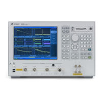
Keysight E5052B Service Manual (265 pages)
Signal Source Analyzer
Brand:
Keysight
| Category:
Measuring Instruments
| Size: 10.14 MB
Table of Contents
Table of Contents
9
General Information
17
Precautions
18
Software Installed
18
Organization of Service Guide
19
Instrument Covered by this Manual
21
Required Equipment
22
Performance Tests
25
Introduction
26
Test Equipment Required
26
Individual Test Description
27
RF in Port VSWR Test
27
Frequency Measurement Test
28
Power Measurement Accuracy Test
29
Phase Noise Accuracy Test
30
SSB Phase Noise Sensitivity Test
31
SA Relative Level Accuracy Test
32
DC Power Voltage Test
33
DC Power Current Measurement Test
34
E5052B Performance Test Calculation Sheet
35
Introduction
35
Phase Noise Accuracy Test
35
SA Relative Level Accuracy Test
37
E5052B Performance Test Record
40
RF in Port VSWR Test
40
Frequency Measurement Test
40
Power Measurement Accuracy Test
42
Phase Noise Accuracy Test
44
SSB Phase Noise Sensitivity Test (for Standard)
45
SSB Phase Noise Sensitivity Test (for Option 011)
45
SA Relative Level Accuracy Test
45
DC Power Voltage Test
47
DC Current Measurement Test
48
Adjustment
49
Safety Considerations
50
Warm-Up for Adjustment
50
Required Equipment
50
Required Adjustment after Replacing Assembly
51
Writing ID
51
DC Control Voltage Adjustment
52
DC Power Voltage Adjustment
52
DC Power Current Adjustment
52
Reference Frequency Adjustment
53
Pre-LO Sampler PLL BW Adjustment
53
Receiver DC Offset Adjustment
53
PM Offset Adjustment
54
PM Linearity Adjustment
55
PM Temp Adjustment
55
PM Flatness Adjustment
56
Receiver RF Flatness Adjustment
56
Receiver if Gain/Flatness Adjustment
57
Receiver RF Flatness dir Adjustment
57
Receiver if Gain/Flatness dir Adjustment
58
LO Sampler PLL BW Adjustment
58
Phase Noise BW Adjustment
59
FLL BW Adjustment
59
Troubleshooting
61
Introduction
62
How to Exit from the E5052B Measurement View
63
To Troubleshoot the Instrument
64
Primary Trouble Isolation
64
No Display Troubleshooting
66
Booting Process Troubleshooting
68
Troubleshooting Using Service Function
72
Power on Test
72
Contents of the Power on Test Results
73
Power on Test Failure Troubleshooting
75
Function Specific Troubleshooting
77
To Check the Device Driver
78
To Check the Front Panel
80
To Check the Touch Panel
81
To Check the LCD
81
To Check the External Keyboard
82
To Check the Mouse
82
To Check the Video Output
82
To Check the External Trigger Input
82
To Check the GPIB
83
To Check the 24-Bit I/O Port
83
To Check the Oven Ch1
83
To Check the Oven Ch2
84
To Check the USB (USBTMC) Interface Card
85
Performance Test Failure Troubleshooting
86
Recommended Adjustment for Performance Test Failure
86
Adjustment Failure Troubleshooting
87
Performance Test Failure Troubleshooting
87
To Configure the A20 Digital Motherboard and BIOS
89
To Identify the Motherboard Installed
89
Testing DRAM on the Motherboard
89
To Confirm or Set the BIOS Options
90
Replaceable Parts
93
Ordering Information
94
Direct Mail Order System
94
Exchange Assemblies
94
Replaceable Parts List
95
Power Cables and Plug Configurations
95
Top View (Major Assemblies)
96
Top View (Cables)
98
Top View (Miscellaneous Parts)
100
Top View (under Power Supply)
102
Top View (Motherboard and Other Parts)
104
Bottom View
106
Front View (Analog Boards)
107
Front View (Cables)
108
Front View (Miscellaneous)
109
Front Panel
110
Rear View
112
Cover Assembly
113
Left Side View
114
Right Side View
115
Removable Hard Disk Drive Assembly
116
PCI DSP Card and GPIB Card Assembly
118
USB Card Assembly
119
PCA Digital Board Assembly
120
Oven Ch1 Assembly
121
Oven Ch2 Assembly
122
DC Block Unit Assembly
123
Analog Mother Board Assembly
124
Freq/Power Detector Module Attachment Assembly
125
DC Source Board Attachment Assembly
126
Local Synthesize Module Assembly
127
Phase Detector Board Assembly
128
Chassis Assembly
130
Front Cover Assembly
132
Front Assembly (LCD)
133
Front Assembly (Standby Switch and PCA Prove Power)
134
Front Assembly (Front Keyboard )
135
Front Assembly (Inverter)
136
Label on Front Face
137
Label on Rear Face
138
Other Parts
139
Replacement Procedure
141
Replacing an Assembly
142
Required Tools
143
Outer Cover Removal
144
Tools Required
144
Procedure
144
Front Panel Removal
146
Tools Required
146
Procedure
146
A27 Removable Hard Disk Assembly Removal
148
Tools Required
148
Removal Procedure
148
Removable Hard Disk Drive Replacement
150
Tools Required
150
Save Backup Files to the PC
150
Removal Procedure
150
Replacement Procedure
151
Restore Backup Files Onto the New Removable Hard Disk Drive
152
Adjustment for the New Removable Hard Disk Drive
152
Calibration of the Touch Screen
152
Power Supply Assembly Replacement
154
Tools Required
154
Removal Procedure
154
Replacement Procedure
155
A26 Digital Bridge Board Replacement
156
Tools Required
156
Removal Procedure
156
Replacement Procedure
157
A25 24 Bit I/O Board Replacement
158
Tools Required
158
Removal Procedure
158
Replacement Procedure
159
A21 PCI DSP / A24 GPIB Card Replacement
160
Tools Required
160
Removal Procedure
160
Replacement Procedure
161
A32 USB (USBTMC) Interface Card Replacement
162
Tools Required
162
Removal Procedure
162
Replacement Procedure
163
Oven CH1 Assembly Replacement
164
Tools Required
164
Removal Procedure
164
Replacement Procedure
165
Oven CH2 Assembly Replacement
166
Tools Required
166
Removal Procedure
166
Replacement Procedure
167
A57 DC Block Assembly Replacement
168
Tools Required
168
Removal Procedure
168
Replacement Procedure
169
Fan Replacement
170
Tools Required
170
Removal Procedure
170
Replacement Procedure
171
A22 Power Distribution Board Replacement
172
Tools Required
172
Removal Procedure
172
Replacement Procedure
173
A20 Digital Motherboard Replacement
174
Tools Required
174
Removal Procedure
174
Replacement Procedure
175
A1 Freq / Power Detector Module Replacement
176
Tools Required
176
Removal Procedure
176
Replacement Procedure
177
A2 DC Source Board Replacement
178
Tools Required
178
Removal Procedure
178
Replacement Procedure
179
A3 ADC/DSP Board Replacement
180
Tools Required
180
Removal Procedure
180
Replacement Procedure
181
A4/A5 Local Synthesize Module Replacement
182
Tools Required
182
Removal Procedure
182
Replacement Procedure
183
A6 Phase Detector Board Replacement
184
Tools Required
184
Removal Procedure
184
Replacement Procedure
185
A50 Analog Motherboard Replacement
186
Tools Required
186
Removal Procedure
186
Replacement Procedure
187
Front Panel Cover Removal
188
Tools Required
188
Removal Procedure
188
Refer to Figure
188
Step 1. Remove the Outer Cover as Described in "Outer Cover Removal" on Page
188
Step 2. Remove the Front Panel as Described in "Front Panel Removal" on Page
188
Control Touch Panel Replacement
189
Tools Required
189
Removal Procedure
189
Replacement Procedure
189
A52 Inverter Assembly Replacement
190
Tools Required
190
Removal Procedure
190
Replacement Procedure
191
A51 LCD Replacement
192
Tools Required
192
Removal Procedure
192
Replacement" on Page
192
Replacement Procedure
193
A22 Front Keyboard Replacement
194
Tools Required
194
Removal Procedure
194
Replacement Procedure
195
Front USB PCA Board Replacement
196
Tools Required
196
Removal Procedure
196
Replacement Procedure
197
Probe Power and Power Switch Board Replacement
198
Tools Required
198
Removal Procedure
198
Replacement Procedure
199
Front BNC Connector Replacement
200
Tools Required
200
Removal Procedure
200
Replacement Procedure
201
Post-Repair Procedures
203
Post-Repair Procedures
204
Manual Changes
209
Manual Changes
210
System Recovery
211
System Recovery
212
Types of System Recoveries
212
Notes on Executing the Factory Recovery Function
213
Procedure to Execute the Factory Recovery (HDD Revision: NM321 or Above)
214
Procedure to Execute the Factory Recovery (HDD Revision: NM320 or Below)
216
Procedure to Create the User Backup Image (Only Available When HDD Revision Is NM320 or Below)
218
Procedure to Execute the User Recovery Function (Only Available When HDD Revision Is NM320 or Below)
225
Initial Registration of E5052B
236
Initial Registration Procedure (HDD Revision: NM321 or Above)
236
Initial Registration Procedure (HDD Revision: NM320 or Below)
239
Calibration of the Touch Screen
241
Firmware Update
243
Firmware Update
244
Required Equipment
244
How to Make E5052B Firmware Installation Device
244
How to Update the E5052B Firmware
244
Power Requirement
249
Power Supply and Blown Fuses
250
Verification of the Power Supply
250
Verification and Connection of Power Cable
250
Blown Fuses
252
Starting the E5052B
253
Turning the Power on and off
253
Disconnection from Supply Source
254
Messages
255
Advertisement
Keysight E5052B Installation Manual (73 pages)
Signal Source Analyzer
Brand:
Keysight
| Category:
Measuring Instruments
| Size: 4.92 MB
Table of Contents
Table of Contents
7
1 Introduction
9
Manuals for E5052B
9
Contents of this Manual
10
2 Installation
11
Checking the Shipment
12
Environmental Requirements
13
Operating Environments
13
Ventilation Requirements
14
Protection against Electrostatic Discharge (ESD)
15
Ensuring Adequate Free Space Around Analyzer for Immediate Disconnection of Power Cable in Case of Emergency
15
Installing Front Handles/Rack Mounting Flanges
16
How to Install the Handle Kit (Option 1CN)
17
How to Install the Rack-Mount Kit (Option 1CM)
18
How to Install the Rack-Mount and Handle Kit (Option 1CP)
18
Connecting the Accessories
19
Connecting Mouse and Keyboard
19
Power Supply
20
Verification of the Power Supply
20
Verification and Connection of Power Cable
20
Blown Fuses
22
Starting the E5052B
23
Turning the Power on and off
23
Disconnection from Supply Source
25
Removing / Mounting Removable Hard Disk
25
Initial Registration of E5052B
26
Windows 7 (HDD Revision Nwxxx) and Windows 10 (HDD Revision Nhxxx)
26
Windows Vista Business (HDD Revision: NM321 or Above)
26
Windows Vista Business (HDD Revision: NM320 or Below)
30
Windows XP Pro for Embedded Systems
32
Online Help
35
3 Troubleshooting
37
Troubleshooting During Startup
37
System Recovery
38
Types of System Recoveries
39
User Recovery (Only for HDD Revision NM320 or Below)
52
Advertisement
Related Products
Keysight E5063A
Keysight E5061B
Keysight E5071C
Keysight E5092A
Keysight E5071C ENA Series
Keysight E5080A
Keysight E5080B
Keysight E5505A
Keysight E4408B
Keysight E7515B
Keysight Categories
Measuring Instruments
Test Equipment
Multimeter
Control Unit
Portable Generator
More Keysight Manuals
Login
Sign In
OR
Sign in with Facebook
Sign in with Google
Upload manual
Upload from disk
Upload from URL