Sign In
Upload
Manuals
Brands
AMX Manuals
Car Video System
Modero NXT-1500VG
AMX Modero NXT-1500VG Manuals
Manuals and User Guides for AMX Modero NXT-1500VG. We have
9
AMX Modero NXT-1500VG manuals available for free PDF download: Operation/Reference Manual, Instruction Manual, Datasheet, Quick Start Manual, Dimension Manual
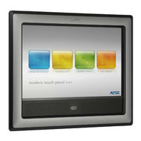
AMX Modero NXT-1500VG Operation/Reference Manual (256 pages)
VG Series Modero Touch Panels
Brand:
AMX
| Category:
Touch Panel
| Size: 5.14 MB
Table of Contents
Table of Contents
5
Introduction
15
Multimedia Streaming Video Touch Panels (VG-Series)
15
Product Specifications (NXD-1200VG and NXT-1200VG)
16
Product Specifications (NXD-1500VG and NXT-1500VG)
19
Product Specifications (NXD-1700VG and NXT-1700VG)
22
NXA-RGB Supported Resolutions and Formats
25
VG-Series Modero Connectors
25
Connecting and Using USB Input Devices
26
Cleaning the Touch Overlay
26
Touch Panel Accessories
27
Overview
27
NXA-AVB/RGB Breakout Box (FG2254-11)
27
Product Specifications
28
RGB RJ-45 Connection and Wiring Information
29
Using the HD-15 High-Density Connector
30
Installing the NXA-AVB/RGB
30
Wiring the NXA-AVB/RGB Connectors and Cables
31
Wiring the NXA-AVB/RGB for Unbalanced Audio
32
Wiring the NXA-AVB/RGB for Balanced Audio
33
Preparing Your Panel for Pass-Thru Control (Using the NXA-AVB/RGB Breakout Box)
33
Wiring for Pass-Thru Computer Control
34
NXA-MTC/RGB Combo Table Top Cable (CA2250-70)
36
Product Specifications
36
Wiring and Connection Information
37
Installing CAT5 Suppression Ferrites
38
NXA-RGB RGB/VGA Interface Card (FG2260)
39
Product Specifications
40
Supported Component/Vga Video Resolutions and Formats
41
RGB RJ-45 Connection and Wiring Information
42
NXA-CFTP Compact Flash (FG2116-22)
42
NXA-PCI80211G Wireless Card (FG2255-04)
43
Product Specifications
44
Installation and Upgrade of the Internal NXT Components
46
Step 1: Remove the Existing NXT Outer Housing
46
Step 2: Install the 802.11G Mini-PCI Wireless Card
47
Step 3: Install the NXA-RGB Card Component (NXT)
48
Step 4: Install the Compact Flash Memory Card Upgrade
49
Step 5: Close and Resecure the NXT Panel Enclosure
50
Installation and Upgrade of the Internal NXD Components
50
Step 1: Remove the Existing NXD Outer Housing
50
Step 2: Install the New 802.11G Mini-PCI Wireless Card (NXD)
51
Step 3: Install the New RGB Card Component (NXD)
51
Step 4: Install the New Compact Flash Memory Card (NXD)
51
Step 5: Close and Resecure the NXD Panel Enclosure
52
NXT-BP Power Pack (FG2255-10)
53
Product Specifications
53
NXA-BASE/B Battery Base Kit (FG2255K)
53
Product Specifications
54
Checking the NXT-BP Battery Charge
54
Installing the NXA-BASE/B to an NXT Modero Panel
54
Installing an NXT-BP into the NXA-BASE/B
56
Charging the NXT-BP Batteries with the NXA-BASE/B
56
NXT-CHG Battery Charger Kit (FG2255-50K)
57
Product Specifications
57
Powering the NXT-CHG
57
Reading NXT-CHG LED Indicator
58
Charging the NXT-BP Batteries Using the NXT-CHG
58
Recalibrating the Batteries
58
Installation Procedures: 12" and 15" Panels
59
Overview
59
Unpacking the Panel
59
Installing Internal Components
59
Upgrading to the MB-TP12/MB-TP15 VESA Mounting Kit
59
Removing the Original Modero Back Box
59
Installing the MP-TP12/15 Back Box
60
Cable Installation for the MP-TP12/15 Back Box
61
Finalizing the Installation
61
Pre-Wall Installation of the Conduit Boxes
63
Installation of the NXD Touch Panel
64
Installing the NXD Panel Within a Conduit Box
64
Installing the NXD into Drywall Using Expansion Clips
66
Installing the NXD into a Flat Surface Using #4 Screws
69
Installing an NXD into an (Optional) Rack Mount Kit (NXA-RK12 or NXA-RK15)
71
Wiring Guidelines for the 1200VG and 1500VG Panels
73
Preparing Captive Wires
73
Wiring a Power Connection
73
Ethernet/Rj-45 Port: Connections and Wiring
74
Audio/Video Port: Connections and Wiring
74
Installation Procedures: 17" Panels
77
Overview
77
Unpacking the Panel
77
Installing the Internal Components
77
Upgrading the Back Box with the MB-TP17 VESA Housing
77
Removing the Original Modero Back Box
77
Installing the MP-TP17 Back Box
78
Cable Installation for the MP-TP17 Back Box
79
Finalizing the Installation
79
Pre-Wall Installation of the CB-TP17 Conduit Box
81
Installation of an NXD-1700VG
83
Installing the NXD-1700VG Within a CB-TP17 Conduit Box
83
Installing the NXD-1700VG into Drywall Using Expansion Clips
85
Installing the NXD-1700VG into a Flat Surface Using #6 Screws
88
Installing an NXD into an (Optional) Rack Mount Kit (NXA-RK17)
91
Wiring Guidelines for the 1700VG Panels
92
Preparing Captive Wires
93
Wiring a Power Connection
93
Audio/Video Port: Connections and Wiring
94
Ethernet/Rj-45 Port: Connections and Wiring
94
Panel Calibration
97
Overview
97
Calibrating the Modero Panel
97
Testing Your Calibration
98
Configuring Communication
99
Overview
99
Modero Setup and System Connection
99
Configuring and Using USB with a Virtual Master
101
Step 1: Setting up the USB Driver on the PC
101
Step 2: Confirming the Installation of the USB Driver on the PC
101
Step 3: Confirm and View the Current AMX USB Device Connections
103
Step 4: Using a USB to Configure a Virtual Master (Using Netlinx Studio)
104
Step 5: Confirm and View the Current AMX USB Device Connections
105
Wireless Settings Page - Wireless Access Overview
106
IP Routing
106
Hot Swapping
106
Configuring a Wireless Connection
107
Step 1: Configuring the Panel's Wireless IP Settings
107
Wireless Communication Using a DHCP Address
107
Wireless Communication Using a Static IP Address
108
Step 2: Configuring the Card's Wireless Security Settings
108
Configuring the Modero's Wireless Card for Unsecured Access to a WAP200G
108
Configuring the Modero's Wireless Card for Secured Access to a WAP200G
110
Configuring Multiple Wireless Moderos to Communicate to a Target WAP200G
112
Configuring a Wired Ethernet Connection
113
Step 1: Configuring the Panel's Wired IP Settings
113
IP Settings Section - Configuring a DHCP Address over Ethernet
113
IP Settings Section - Configuring a Static IP Address over Ethernet
113
Step 2: Choosing a Master Connection Mode Setting
114
Step 3: Configuring the Ethernet Connection Type
114
Master Connection - Virtual Master Communication over Ethernet
115
Master Connection Section - Netlinx Master Ethernet IP Address - URL Mode
117
Master Connection Section - Netlinx Master Ethernet IP Address - Listen Mode
118
Master Connection Section - Netlinx Master Ethernet IP Address - Auto Mode
118
Using G4 Web Control to Interact with a G4 Panel
119
Using Your Netlinx Master to Control the G4 Panels
121
Upgrading Modero Firmware
123
Overview
123
Upgrading the Modero Firmware Via the USB Port
123
Step 1: Configure the Panel for a USB Connection Type
123
Step 2: Prepare Netlinx Studio for Communication Via the USB Port
124
Step 3: Confirm and Upgrade the Firmware Via the USB Port
125
Upgrading the Modero Firmware Via an IP Address
127
Step 1: Prepare the Master for Communication Via an IP
127
Step 2: Prepare the Panel for Communication Via an IP
128
Step 3: Verify and Upgrade the Panel Firmware Via an IP
128
Upgrading Accessory Devices Via an IP Address
130
Step 1: Prepare the NXA-BASE/B for Firmware Transfer
131
Step 2: Upgrade the NXA-BASE/B Firmware Via an IP
131
Upgrading the NXA-RGB and NXA-AVB/RGB Firmware
133
Firmware Pages and Descriptions
135
Overview
135
Setup Navigation Buttons
135
Setup Page
136
Panel Information Page
138
Project Information Page
139
Time & Date Settings Page
140
Audio Settings Page
142
Supported Sampling Rates for WAV
143
Information Icon
143
Protected Setup Page
143
Video Slide-Out Menu
144
Video Settings Page
144
Video - RGB Settings Page
145
Adjusting the Incoming Signal on the RGB Settings Page
148
Video - Streaming Settings Page
151
Battery Base Page
154
Protected Setup Navigation Buttons
156
Protected Setup Page
157
Security Settings
159
Security Profile Features
159
System Settings Page
161
Sensor Settings Page
163
Using the Automated Brightness Control Feature (DIM Mode)
164
Calibration Page
166
G4 Web Control Settings
167
Other Settings Slide-Out Menu
169
Cache Settings Page
169
Setting the Image Cache
171
Clearing the Image Cache
171
Checking Image Cache Status
171
Password Settings Page
172
Tools Slide-Out Menu
173
Panel Connection Logs Page Elements
173
Checking the Panel Connection Logs
174
Refreshing the Panel Connections Log
174
Clearing the Panel Connections Log
174
Panel Statistics Page Elements
175
Checking the Panel Statistics
176
Refreshing the Panel Statistics
176
Clearing the Panel Statistics
176
Connection Utility
177
Using the Connection Utility
178
Wireless Settings Page
179
Displaying Stream Content
183
Overview
183
Requirements for Receiving Streamed Content
184
Setting up a Modero Panel to Receive and Display a Stream
185
Step 1: Obtaining the IP Address of the Target Panel
185
Step 2: Configuring the MAX-CSE for Communication
185
Step 3: Configuring the MAX-CSE Audio/Video Inputs
187
Step 4: Setup a Streaming Page Within Tpdesign4
188
Step 5: Establishing the Final Connection between the Two Units
191
Advertisement
AMX Modero NXT-1500VG Operation/Reference Manual (232 pages)
VG Series Modero 12" / 15"/ 17"
Brand:
AMX
| Category:
Touch Panel
| Size: 5.16 MB
Table of Contents
Table of Contents
5
Introduction
15
Multimedia Streaming Video Touch Panels (VG-Series)
15
Product Specifications (NXD-1200VG and NXT-1200VG)
16
Product Specifications (NXD-1500VG and NXT-1500VG)
19
Product Specifications (NXD-1700VG and NXT-1700VG)
22
NXA-RGB Supported Resolutions and Formats
24
VG-Series Modero Connectors
25
Connecting and Using USB Input Devices
25
Cleaning the Touch Overlay
25
Touch Panel Accessories
27
Overview
27
NXA-AVB/RGB Breakout Box (FG2254-11)
27
Product Specifications
28
RGB RJ-45 Connection and Wiring Information
29
Using the HD-15 High-Density Connector
30
Installing the NXA-AVB/RGB
30
Wiring the NXA-AVB/RGB Connectors and Cables
31
Wiring the NXA-AVB/RGB for Unbalanced Audio
32
Wiring the NXA-AVB/RGB for Balanced Audio
32
Preparing Your Panel for Pass-Thru Control (Using the NXA-AVB/RGB Breakout Box)
33
Wiring for Pass-Thru Computer Control
34
NXA-MTC/RGB Combo Table Top Cable (CA2250-70)
35
Product Specifications
35
Wiring and Connection Information
36
Installing CAT5 Suppression Ferrites
37
NXA-RGB RGB/VGA Interface Card (FG2260)
38
Product Specifications
39
Supported Component/Vga Video Resolutions and Formats
40
RGB RJ-45 Connection and Wiring Information
40
NXA-CFTP Compact Flash (FG2116-22)
41
NXA-PCI80211G Wireless Card (FG2255-04)
41
Product Specifications
42
Installation and Upgrade of the Internal NXT Components
44
Step 1: Remove the Existing NXT Outer Housing
44
Step 2: Install the 802.11G Mini-PCI Wireless Card
45
Step 3: Install the NXA-RGB Card Component (NXT)
46
Step 4: Install the Compact Flash Memory Card Upgrade
47
Step 5: Close and Resecure the NXT Panel Enclosure
48
Installation and Upgrade of the Internal NXD Components
48
Step 1: Remove the Existing NXD Outer Housing
48
Step 2: Install the New 802.11G Mini-PCI Wireless Card (NXD)
49
Step 3: Install the New RGB Card Component (NXD)
49
Step 4: Install the New Compact Flash Memory Card (NXD)
49
Step 5: Close and Resecure the NXD Panel Enclosure
50
NXT-BP Power Pack (FG2255-10)
51
Product Specifications
51
NXA-BASE/B Battery Base Kit (FG2255K)
51
Product Specifications
52
Checking the NXT-BP Battery Charge
52
Installing the NXA-BASE/B to an NXT Modero Panel
52
Installing an NXT-BP into the NXA-BASE/B
54
Charging the NXT-BP Batteries with the NXA-BASE/B
54
NXT-CHG Battery Charger Kit (FG2255-50K)
55
Product Specifications
55
Powering the NXT-CHG
55
Reading NXT-CHG LED Indicator
56
Charging the NXT-BP Batteries Using the NXT-CHG
56
Recalibrating the Batteries
56
Installation Procedures: 12" and 15" Panels
57
Overview
57
Unpacking the Panel
57
Installing Internal Components
57
Upgrading to the MB-TP12/MB-TP15 VESA Mounting Kit
57
Removing the Original Modero Back Box
57
Installing the MP-TP12/15 Back Box
58
Cable Installation for the MP-TP12/15 Back Box
59
Finalizing the Installation
59
Pre-Wall Installation of the Conduit Boxes
61
Installation of the NXD Touch Panel
62
Installing the NXD Panel Within a Conduit Box
62
Installing the NXD into Drywall Using Expansion Clips
64
Installing the NXD into a Flat Surface Using #4 Screws
66
Installing an NXD into an (Optional) Rack Mount Kit (NXA-RK12 or NXA-RK15)
69
Wiring Guidelines for the 1200VG and 1500VG Panels
71
Preparing Captive Wires
71
Wiring a Power Connection
71
Audio/Video Port: Connections and Wiring
72
Ethernet/Rj-45 Port: Connections and Wiring
72
Installation Procedures: 17" Panels
73
Overview
73
Unpacking the Panel
73
Installing the Internal Components
73
Upgrading the Back Box with the MB-TP17 VESA Housing
73
Removing the Original Modero Back Box
73
Installing the MP-TP17 Back Box
74
Cable Installation for the MP-TP17 Back Box
75
Finalizing the Installation
75
Pre-Wall Installation of the CB-TP17 Conduit Box
77
Installation of an NXD-1700VG
79
Installing the NXD-1700VG Within a CB-TP17 Conduit Box
79
Installing the NXD-1700VG into Drywall Using Expansion Clips
81
Installing the NXD-1700VG into a Flat Surface Using #6 Screws
84
Installing an NXD into an (Optional) Rack Mount Kit (NXA-RK17)
87
Wiring Guidelines for the 1700VG Panels
88
Preparing Captive Wires
88
Wiring a Power Connection
89
Audio/Video Port: Connections and Wiring
89
Ethernet/Rj-45 Port: Connections and Wiring
90
Panel Calibration
91
Overview
91
Calibrating the Modero Panel
91
Testing Your Calibration
92
Configuring Communication
93
Overview
93
Modero Setup and System Connection
93
Configuring and Using USB with a Virtual Master
95
Step 1: Setting up the USB Driver on the PC
95
Step 2: Confirming the Installation of the USB Driver on the PC
95
Step 3: Confirm and View the Current AMX USB Device Connections
97
Step 4: Using a USB to Configure a Virtual Master (Using Netlinx Studio)
98
Step 5: Confirm and View the Current AMX USB Device Connections
99
Wireless Settings Page - Wireless Access Overview
100
IP Routing
100
Hot Swapping
100
Configuring a Wireless Connection
100
Step 1: Configuring the Panel's Wireless IP Settings
100
Wireless Communication Using a DHCP Address
101
Wireless Communication Using a Static IP Address
101
Step 2: Configuring the Card's Wireless Security Settings
102
Configuring the Modero's Wireless Card for Unsecured Access to a WAP200G
102
Configuring the Modero's Wireless Card for Secured Access to a WAP200G
103
Configuring Multiple Wireless Moderos to Communicate to a Target WAP200G
106
Configuring a Wired Ethernet Connection
106
Step 1: Configuring the Panel's Wired IP Settings
106
IP Settings Section - Configuring a DHCP Address over Ethernet
106
IP Settings Section - Configuring a Static IP Address over Ethernet
107
Step 2: Choosing a Master Connection Mode Setting
107
Step 3: Configuring the Ethernet Connection Type
108
Master Connection - Virtual Master Communication over Ethernet
109
Master Connection Section - Netlinx Master Ethernet IP Address - URL Mode
110
Master Connection Section - Netlinx Master Ethernet IP Address - Listen Mode
111
Master Connection Section - Netlinx Master Ethernet IP Address - Auto Mode
111
Using G4 Web Control to Interact with a G4 Panel
112
Using Your Netlinx Master to Control the G4 Panels
113
Upgrading Modero Firmware
117
Overview
117
Upgrading the Modero Firmware Via the USB Port
117
Step 1: Configure the Panel for a USB Connection Type
117
Step 2: Prepare Netlinx Studio for Communication Via the USB Port
118
Step 3: Confirm and Upgrade the Firmware Via the USB Port
119
Upgrading the Modero Firmware Via an IP Address
121
Step 1: Prepare the Master for Communication Via an IP
121
Step 2: Prepare the Panel for Communication Via an IP
122
Step 3: Verify and Upgrade the Panel Firmware Via an IP
122
Upgrading Accessory Devices Via an IP Address
124
Step 1: Prepare the NXA-BASE/B for Firmware Transfer
124
Step 2: Upgrade the NXA-BASE/B Firmware Via an IP
125
Upgrading the NXA-RGB and NXA-AVB/RGB Firmware
126
Firmware Pages and Descriptions
129
Overview
129
Setup Navigation Buttons
129
Setup Page
130
Panel Information Page
131
Project Information Page
132
Time & Date Settings Page
133
Audio Settings Page
134
Supported Sampling Rates for WAV
135
Information Icon
135
Protected Setup Page
136
Video Slide-Out Menu
136
Video Settings Page
136
Video - RGB Settings Page
137
Adjusting the Incoming Signal on the RGB Settings Page
140
Video - Streaming Settings Page
142
Battery Base Page
144
Protected Setup Navigation Buttons
146
Protected Setup Page
147
Security Settings
149
System Settings Page
150
Sensor Settings Page
151
Using the Automated Brightness Control Feature (DIM Mode)
153
Calibration Page
154
G4 Web Control Settings
154
Other Settings Slide-Out Menu
156
Cache Settings Page
156
Setting the Image Cache
157
Clearing the Image Cache
158
Checking Image Cache Status
158
Password Settings Page
158
Tools Slide-Out Menu
158
Panel Connection Logs Page Elements
159
Checking the Panel Connection Logs
159
Refreshing the Panel Connections Log
159
Clearing the Panel Connections Log
159
Panel Statistics Page Elements
160
Checking the Panel Statistics
161
Refreshing the Panel Statistics
161
Clearing the Panel Statistics
161
Connection Utility
161
Using the Connection Utility
162
Wireless Settings Page
162
Displaying Stream Content
167
Overview
167
Requirements for Receiving Streamed Content
168
Setting up a Modero Panel to Receive and Display a Stream
168
Step 1: Obtaining the IP Address of the Target Panel
168
Step 2: Configuring the MAX-CSE for Communication
169
Step 3: Configuring the MAX-CSE Audio/Video Inputs
171
Step 4: Setup a Streaming Page Within Tpdesign4
172
Step 5: Establishing the Final Connection between the Two Units
174
AMX Modero NXT-1500VG Instruction Manual (187 pages)
MODERO VG SERIES WALL/FLUSH MOUNT TOUCH PANELS
Brand:
AMX
| Category:
Touch Panel
| Size: 5.4 MB
Table of Contents
Copyright Notice
2
Table of Contents
3
Modero VG Series Touch Panels
12
Overview
12
Multimedia Streaming Video Touch Panels (VG-Series)
12
Product Specifications - NXD/T-1200VG
13
Product Specifications - NXD/T-1500VG
15
Product Specifications - NXD/T-1700VG
17
NXA-RGB Supported Resolutions and Formats
19
VG-Series Modero Connectors
19
Connecting and Using USB Input Devices
20
Cleaning the Touch Overlay
20
Touch Panel Accessories
21
Overview
21
NXA-AVB/RGB Breakout Box (FG2254-11)
21
Product Specifications
21
RGB RJ-45 Connection and Wiring Information
22
Using the HD-15 High-Density Connector
23
Installing the NXA-AVB/RGB
23
Wiring the NXA-AVB/RGB Connectors and Cables
24
Wiring the NXA-AVB/RGB for Unbalanced Audio
25
Wiring the NXA-AVB/RGB for Balanced Audio
25
Preparing Your Panel for Pass-Thru Control (Using the NXA-AVB/RGB Breakout Box)
25
Wiring for Pass-Thru Computer Control
26
NXA-MTC/RGB Combo Table Top Cable (CA2250-70)
27
Product Specifications
27
Wiring and Connection Information
28
Installing CAT5 Suppression Ferrites
28
NXA-RGB RGB/VGA Interface Card (FG2260)
29
Product Specifications
30
Supported Component/Vga Video Resolutions and Formats
30
RGB RJ-45 Connection and Wiring Information
31
NXA-CFTP Compact Flash (FG2116-22)
31
NXA-PCI80211G Wireless Card (FG2255-04)
31
Product Specifications
32
Installation and Upgrade of the Internal NXT Components
33
Step 1: Remove the Existing NXT Outer Housing
33
Step 2: Install the 802.11G Mini-PCI Wireless Card
34
Step 3: Install the NXA-RGB Card Component (NXT)
35
Step 4: Install the Compact Flash Memory Card Upgrade
36
Step 5: Close and Re-Secure the NXT Panel Enclosure
37
Installation and Upgrade of the Internal NXD Components
37
Step 1: Remove the Existing NXD Outer Housing
37
Step 2: Install the New 802.11G Mini-PCI Wireless Card (NXD)
37
Step 3: Install the New RGB Card Component (NXD)
38
Step 4: Install the New Compact Flash Memory Card (NXD)
38
Step 5: Close and Resecure the NXD Panel Enclosure
38
NXT-BP Power Pack (FG2255-10)
39
Product Specifications
39
NXA-BASE/B Battery Base Kit (FG2255K)
39
Checking the NXT-BP Battery Charge
40
Installing the NXA-BASE/B to an NXT Modero Panel
40
Installing an NXT-BP into the NXA-BASE/B
41
Charging the NXT-BP Batteries with the NXA-BASE/B
42
NXT-CHG Battery Charger Kit (FG2255-50K)
42
Product Specifications
42
Powering the NXT-CHG
42
Reading NXT-CHG LED Indicator
43
Charging the NXT-BP Batteries Using the NXT-CHG
43
Recalibrating the Batteries
43
Installation Procedures: 12" and 15" Panels
44
Overview
44
Unpacking the Panel
44
Installing Internal Components
44
Upgrading to the MB-TP12/MB-TP15 VESA Mounting Kit
44
Removing the Original Modero Back Box
44
Installing the MP-TP12/15 Back Box
45
Cable Installation for the MP-TP12/15 Back Box
46
Finalizing the Installation
46
Pre-Wall Installation of the Conduit Boxes
47
Installation of the NXD Touch Panel
48
Installing the NXD Panel Within a Conduit Box
48
Installing the NXD into Drywall Using Expansion Clips
49
Installing the NXD into a Flat Surface Using #4 Screws
52
Installing an NXD into an (Optional) Rack Mount Kit (NXA-RK12 or NXA-RK15)
54
Wiring Guidelines for the 1200VG and 1500VG Panels
56
Preparing Captive Wires
56
Wiring a Power Connection
56
Audio/Video Port: Connections and Wiring
56
Ethernet/Rj-45 Port: Connections and Wiring
57
Overview
58
Unpacking the Panel
58
Installing the Internal Components
58
Upgrading the Back Box with the MB-TP17 VESA Housing
58
Removing the Original Modero Back Box
58
Installing the MP-TP17 Back Box
59
Cable Installation for the MP-TP17 Back Box
59
Finalizing the Installation
59
Installation Procedures: 17" Panels
58
Pre-Wall Installation of the CB-TP17 Conduit Box
61
Installation of an NXD-1700VG
63
Installing the NXD-1700VG Within a CB-TP17 Conduit Box
63
Installing the NXD-1700VG into Drywall Using Expansion Clips
64
Installing the NXD-1700VG into a Flat Surface Using #6 Screws
67
Installing an NXD into an (Optional) Rack Mount Kit (NXA-RK17)
69
Wiring Guidelines for the 1700VG Panels
70
Preparing Captive Wires
70
Wiring a Power Connection
70
Audio/Video Port: Connections and Wiring
70
Ethernet/Rj-45 Port: Connections and Wiring
71
Panel Calibration
72
Overview
72
Calibrating the Modero Panel
72
Testing Calibration
73
Configuring Communication
74
Overview
74
Modero Setup and System Connection
74
Configuring and Using USB with a Virtual Master
75
Step 1: Setting up the USB Driver on the PC
75
Step 2: Confirming the Installation of the USB Driver on the PC
76
Step 3: Confirm and View the Current AMX USB Device Connections
77
Step 4: Using a USB to Configure a Virtual Master (Using Netlinx Studio)
77
Step 5: Confirm and View the Current AMX USB Device Connections
78
Wireless Settings Page - Wireless Access Overview
79
IP Routing
79
Hot Swapping
79
Configuring a Wireless Connection
80
Step 1: Configuring the Panel's Wireless IP Settings
80
Wireless Communication Using a DHCP Address
80
Wireless Communication Using a Static IP Address
80
Step 2: Configuring the Card's Wireless Security Settings
81
Configuring the Modero's Wireless Card for Unsecured Access to a WAP200G
81
Configuring the Modero's Wireless Card for Secured Access to a WAP200G
82
Configuring Multiple Wireless Moderos to Communicate to a Target WAP200G
84
Configuring a Wired Ethernet Connection
84
Step 1: Configuring the Panel's Wired IP Settings
84
IP Settings Section - Configuring a DHCP Address over Ethernet
84
IP Settings Section - Configuring a Static IP Address over Ethernet
84
Step 2: Choosing a Master Connection Mode Setting
85
Step 3: Configuring the Ethernet Connection Type
85
Master Connection - Virtual Master Communication over Ethernet
86
Master Connection Section - Netlinx Master Ethernet IP Address - URL Mode
87
Master Connection Section - Netlinx Master Ethernet IP Address - Listen Mode
87
Master Connection Section - Netlinx Master Ethernet IP Address - Auto Mode
88
Using G4 Web Control to Interact with a G4 Panel
88
Using Your Netlinx Master to Control the G4 Panels
90
Upgrading Modero Firmware
92
Overview
92
Upgrading the Modero Firmware Via the USB Port
92
Step 1: Configure the Panel for a USB Connection Type
92
Step 2: Prepare Netlinx Studio for Communication Via the USB Port
92
Step 3: Confirm and Upgrade the Firmware Via the USB Port
93
Upgrading the Modero Firmware Via an IP Address
95
Step 1: Prepare the Master for Communication Via an IP
95
Step 2: Prepare the Panel for Communication Via an IP
96
Step 3: Verify and Upgrade the Panel Firmware Via an IP
96
Upgrading Accessory Devices Via an IP Address
97
Step 1: Prepare the NXA-BASE/B for Firmware Transfer
98
Step 2: Upgrade the NXA-BASE/B Firmware Via an IP
98
Upgrading NXA-RGB and NXA-AVB/RGB Firmware
100
Firmware Pages and Descriptions
101
Overview
101
Setup Navigation Buttons
101
Setup Page
102
Panel Information Page
103
Project Information Page
104
Time & Date Settings Page
105
Audio Settings Page
106
Supported Sampling Rates for WAV
106
Information Icon
107
Protected Setup Page
107
Video Slide-Out Menu
107
Video Settings Page
107
Video - RGB Settings Page
108
Adjusting the Incoming Signal on the RGB Settings Page
110
Video - Streaming Settings Page
112
Battery Base Page
114
Protected Setup Navigation Buttons
116
Protected Setup Page
117
Security Settings
118
System Settings Page
119
Sensor Settings Page
120
Using the Automated Brightness Control Feature (DIM Mode)
121
Calibration Page
122
G4 Web Control Settings
122
Other Settings Slide-Out Menu
123
Cache Settings Page
124
Setting the Image Cache
125
Clearing the Image Cache
125
Checking Image Cache Status
125
Password Settings Page
126
Tools Slide-Out Menu
126
Panel Connection Logs
126
Checking the Panel Connection Logs
127
Refreshing the Panel Connections Log
127
Clearing the Panel Connections Log
127
Panel Statistics Page Elements
127
Checking the Panel Statistics
128
Refreshing the Panel Statistics
128
Clearing the Panel Statistics
128
Connection Utility
128
Using the Connection Utility
129
Wireless Settings Page
129
Displaying Stream Content
133
Overview
133
Requirements for Receiving Streamed Content
133
Setting up a Modero Panel to Receive and Display a Stream
134
Step 1: Obtaining the IP Address of the Target Panel
134
Step 2: Configuring the MAX-CSE for Communication
134
Step 3: Configuring the MAX-CSE Audio/Video Inputs
136
Step 4: Setup a Streaming Page Within Tpdesign4
137
Step 5: Establishing the Final Connection between the Two Units
138
Button Assignments
140
Page Commands
140
Apg
140
Cpg
140
Dpg
140
Pdr
141
Phe
141
Php
141
Pht
141
Ppa
141
Ppf
141
Ppg
142
Ppk
142
Ppm
142
Ppn
142
Ppt
142
Ppx
143
Pse
143
Psp
143
Pst
143
Ppof
143
Ppog
144
Ppon
144
Advertisement
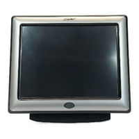
Amx Modero NXT-1500VG Operation/Reference Manual (252 pages)
Modero VG-Series G4 Touch Panels
Brand:
Amx
| Category:
Touch Panel
| Size: 6.64 MB
Table of Contents
Table of Contents
5
Introduction
11
Multimedia Streaming Video Touch Panels (VG-Series)
11
Product Specifications (NXD-1200VG and NXT-1200VG)
12
Product Specifications (NXD-1500VG and NXT-1500VG)
17
Product Specifications (NXD-1700VG and NXT-1700VG)
22
VG-Series Modero Connectors
27
Connecting and Using USB Input Devices
27
Cleaning the Touch Overlay
28
Touch Panel Accessories
29
Overview
29
NXA-AVB/RGB Breakout Box (FG2254-11)
29
Product Specifications
30
RGB RJ-45 Connection and Wiring Information
31
Using the HD-15 High-Density Connector
32
Installing the NXA-AVB/RGB
32
Wiring the NXA-AVB/RGB Connectors and Cables
33
Wiring the NXA-AVB/RGB for Unbalanced Audio
34
Wiring the NXA-AVB/RGB for Balanced Audio
35
Preparing Your Panel for Pass-Thru Control (Using the NXA-AVB/RGB Breakout Box)
36
Wiring for Pass-Thru Computer Control
37
NXA-MTC/RGB Combo Table Top Cable (CA2250-70)
38
Product Specifications
38
Wiring and Connection Information
39
Installing CAT5 Suppression Ferrites
40
NXA-RGB RGB/VGA Interface Card (FG2260)
41
Product Specifications
42
Supported Component/Vga Video Resolutions and Formats
43
RGB RJ-45 Connection and Wiring Information
43
NXA-CFTP Compact Flash (FG2116-22)
44
NXA-PCI80211G Wireless Card (FG2255-04)
45
Product Specifications
45
Installation and Upgrade of the Internal NXT Components
47
Step 1: Remove the Existing NXT Outer Housing
47
Step 2: Install the 802.11G Mini-PCI Wireless Card
48
Step 3: Install the NXA-RGB Card Component (NXT)
49
Step 4: Install the Compact Flash Memory Card Upgrade
50
Step 5: Close and Resecure the NXT Panel Enclosure
51
Installation and Upgrade of the Internal NXD Components
52
Step 1: Remove the Existing NXD Outer Housing
52
Step 2: Install the New 802.11G Mini-PCI Wireless Card (NXD)
53
Step 3: Install the New RGB Card Component (NXD)
53
Step 4: Install the New Compact Flash Memory Card (NXD)
53
Step 5: Close and Resecure the NXD Panel Enclosure
53
NXT-BP Power Pack (FG2255-10)
54
Product Specifications
54
NXA-BASE/B Battery Base Kit (FG2255K)
55
Product Specifications
55
Checking the NXT-BP Battery Charge
56
Installing the NXA-BASE/B to an NXT Modero Panel
56
Installing an NXT-BP into the NXA-BASE/B
57
Charging the NXT-BP Batteries with the NXA-BASE/B
58
NXT-CHG Battery Charger Kit (FG2255-50K)
59
Product Specifications
59
Powering the NXT-CHG
60
Reading NXT-CHG LED Indicator
60
Charging the NXT-BP Batteries Using the NXT-CHG
60
Recalibrating the Batteries
61
Installation Procedures: 12" and 15" Panels
63
Overview
63
Unpacking the Panel
63
Installing Internal Components
63
Upgrading to the MB-TP12/MB-TP15 VESA Mounting Kit
63
Removing the Original Modero Back Box
64
Installing the MP-TP12/15 Back Box
64
Cable Installation for the MP-TP12/15 Back Box
65
Finalizing the Installation
65
Pre-Wall Installation of the Conduit Boxes
68
Installation of the NXD Touch Panel
69
Installing the NXD Panel Within a Conduit Box
69
Installing the NXD into Drywall Using Expansion Clips
70
Installing the NXD into a Flat Surface Using #4 Screws
73
Installing an NXD into an (Optional) Rack Mount Kit (NXA-RK12 or NXA-RK15)
76
Wiring Guidelines for the 1200VG and 1500VG Panels
78
Preparing Captive Wires
78
Wiring a Power Connection
78
Ethernet/Rj-45 Port: Connections and Wiring
79
Audio/Video Port: Connections and Wiring
79
Installation Procedures: 17" Panels
81
Overview
81
Unpacking the Panel
81
Installing the Internal Components
81
Upgrading the Back Box with the MB-TP17 VESA Housing
81
Removing the Original Modero Back Box
81
Installing the MP-TP17 Back Box
82
Cable Installation for the MP-TP17 Back Box
83
Finalizing the Installation
83
Pre-Wall Installation of the CB-TP17 Conduit Box
85
Installation of an NXD-1700VG
87
Installing the NXD-1700VG Within a CB-TP17 Conduit Box
87
Installing the NXD-1700VG into Drywall Using Expansion Clips
89
Installing the NXD-1700VG into a Flat Surface Using #6 Screws
93
Installing an NXD into an (Optional) Rack Mount Kit (NXA-RK17)
96
Wiring Guidelines for the 1700VG Panels
97
Preparing Captive Wires
97
Wiring a Power Connection
97
Audio/Video Port: Connections and Wiring
98
Ethernet/Rj-45 Port: Connections and Wiring
98
Panel Calibration
101
Overview
101
Calibrating the Modero Panel
101
Testing Your Calibration
102
Configuring Communication
103
Overview
103
Modero Setup and System Connection
103
Configuring and Using USB with a Virtual Master
105
Step 1: Setting up the USB Driver on the PC
105
Step 2: Confirming the Installation of the USB Driver on the PC
106
Step 3: Confirm and View the Current AMX USB Device Connections
108
Step 4: Using a USB to Configure a Virtual Master (Using Netlinx Studio)
108
Step 5: Confirm and View the Current AMX USB Device Connections
110
Wireless Settings Page - Wireless Access Overview
111
IP Routing
111
Hot Swapping
111
Configuring a Wireless Connection
112
Step 1: Configuring the Panel's Wireless IP Settings
112
Wireless Communication Using a DHCP Address
112
Wireless Communication Using a Static IP Address
113
Step 2: Configuring the Card's Wireless Security Settings
114
Configuring the Modero's Wireless Card for Unsecured Access to a WAP200G
114
Configuring the Modero's Wireless Card for Secured Access to a WAP200G
115
Configuring Multiple Wireless Moderos to Communicate to a Target WAP200G
118
Configuring a Wired Ethernet Connection
119
Step 1: Configuring the Panel's Wired IP Settings
119
IP Settings Section - Configuring a DHCP Address over Ethernet
119
IP Settings Section - Configuring a Static IP Address over Ethernet
120
Step 2: Choosing a Master Connection Mode Setting
120
Step 3: Configuring the Ethernet Connection Type
121
Master Connection - Virtual Master Communication over Ethernet
122
Master Connection Section - Netlinx Master Ethernet IP Address - URL Mode
124
Master Connection Section - Netlinx Master Ethernet IP Address - Listen Mode
124
Master Connection Section - Netlinx Master Ethernet IP Address - Auto Mode
125
Using G4 Web Control to Interact with a G4 Panel
126
Using Your Netlinx Master to Control the G4 Panels
128
Amx Modero NXT-1500VG Operation/Reference Manual (46 pages)
Amx Modero NXD-CA12 Touch Panels: Reference Guide
Brand:
Amx
| Category:
Software
| Size: 0.7 MB
Table of Contents
Table of Contents
3
G4 Panelbuilder Overview
7
Welcome to G4 Panelbuilder
7
System Requirements
7
Supported AMX (G4) Touch Panel Types
7
The G4 Panelbuilder Work Area
8
G4 Panelbuilder Application Interface
8
File Menu
9
Edit Menu
9
Project Menu
9
Toolbox Menu
9
Diagram Menu
10
View Menu
10
Help Menu
10
Diagram Area
11
Toolbar
11
Tasks Pane
12
Quick Links
13
Toolbox
13
Color Schemes
14
Status Bar
14
Viewing Panes
14
Changing Visual Style
14
Basic Operations
15
Getting Started
15
Creating a New Project
15
Adding a Toolbox Element to the Diagram
15
Adding Elements Via the Diagram Menu
16
Connecting Elements
16
Editing Diagram Element Properties Via the Diagram Menu
17
Generating a Tpdesign4 Project
17
Saving a Project
17
Closing a Project
18
Templates
18
Preview a Template Via Template Manager
18
Opening a most Recently Used Template
18
Install a Template Via Template Manager
18
Install Templates from Amx.com
18
Install a Template from File
19
Remove a Template from G4 Panelbuilder
19
Opening a Project
19
Changing Color Schemes
19
Creating a New Project from File
20
Editing Project Properties
20
Alternate Screen Names
20
Using Unicode Text
20
Preview Diagram Element
21
Preview a Toolbox Element
21
Globally Remove an Element Instance
21
Undo, Redo and Delete
21
Create Snapshots to Clipboard
22
Show and Hide Grid
22
Snap to Grid
22
Zoom in and out of Diagram
22
Using Web Updates
22
Exiting G4 Panelbuilder
22
Amx Modero NXT-1500VG Datasheet (3 pages)
15” Modero Multimedia Touch Panel
Brand:
Amx
| Category:
Touch Panel
| Size: 0.76 MB
AMX Modero NXT-1500VG Quick Start Manual (2 pages)
Multimedia Touch Panel (G4)
Brand:
AMX
| Category:
Car Video System
| Size: 0.32 MB
Amx Modero NXT-1500VG Quick Start Manual (2 pages)
Combo Table Top Cable for VG-Series Panels
Brand:
Amx
| Category:
Cables and connectors
| Size: 0.29 MB
Amx Modero NXT-1500VG Dimension Manual (1 page)
15" TILT
Brand:
Amx
| Category:
Touch Panel
| Size: 0.1 MB
Advertisement
Related Products
AMX Modero NXD-1500VG
AMX Modero NXT-1200V
AMX Modero NXT-1200VG
Amx Modero NXT-1700VG
AMX Modero NXT-CV7
Amx MODERO NXT-CA12
Amx modero NXT-CA15
Amx modero NXT-CV15
Amx modero NXT-CV17
Amx Modero NXT-CV10
AMX Categories
Touch Panel
Matrix Switcher
Controller
Switch
Keypad
More AMX Manuals
Login
Sign In
OR
Sign in with Facebook
Sign in with Google
Upload manual
Upload from disk
Upload from URL