AMX NXD-1200VG Operation/Reference Manual
Vg series modero 12" / 15"/ 17"
Hide thumbs
Also See for NXD-1200VG:
- Datasheet (3 pages) ,
- Quick start manual (2 pages) ,
- Dimension manual (1 page)
Table of Contents
Advertisement
Quick Links
Download this manual
See also:
Instruction Manual
Advertisement
Table of Contents

Related Manuals for AMX NXD-1200VG


Summary of Contents for AMX NXD-1200VG
- Page 1 Operation/Reference Guide ® VG Series Modero Touch Panels NXD/T-1200VG 12" Modero Touch Panel NXD/T-1500VG 15" Modero Touch Panel NXD/T-1700VG 17" Modero Touch Panel T o u c h P a n e l s L a s t R e v i s e d : 1 2 / 1 9 / 2 0 1 2...
- Page 2 AMX is not responsible for products returned without a valid RMA number. AMX is not liable for any damages caused by its products or for the failure of its products to perform. This includes any lost profits, lost savings, incidental damages, or consequential damages.
- Page 3 LICENSE GRANT. AMX grants to Licensee the non-exclusive right to use the AMX Software in the manner described in this License. The AMX Software is licensed, not sold. This license does not grant Licensee the right to create derivative works of the AMX Software.
- Page 4 FCC Information This device complies with Part 15 of the FCC Rules. Operation is subject to the following two conditions: (1) this device may not cause harmful interference, and (2) this device must accept any interference received; including interference that may cause undesired operation. Federal Communications Commission (FCC) Statement This equipment has been tested and found to comply with the limits for a Class B digital device, pursuant to Part 15 of...
-
Page 5: Table Of Contents
Table of Contents Table of Contents Introduction ......................1 Multimedia Streaming Video Touch Panels (VG-Series)..........1 Product Specifications (NXD-1200VG and NXT-1200VG)..........2 Product Specifications (NXD-1500VG and NXT-1500VG)..........5 Product Specifications (NXD-1700VG and NXT-1700VG)..........8 NXA-RGB Supported Resolutions and Formats............. 10 VG-Series Modero Connectors ................11 Connecting and Using USB Input Devices .............. - Page 6 Table of Contents Installation and Upgrade of the Internal NXD Components ........34 Step 1: Remove the existing NXD Outer Housing............34 Step 2: Install the new 802.11g mini-PCI Wireless card (NXD) ........35 Step 3: Install the new RGB Card Component (NXD) ............ 35 Step 4: Install the new Compact Flash Memory card (NXD) ..........
- Page 7 Step 2: Confirming the Installation of the USB Driver on the PC ........81 Step 3: Confirm and View the current AMX USB device connections ......83 Step 4: Using a USB to Configure a Virtual Master (using NetLinx Studio) ....84 Step 5: Confirm and View the current AMX USB device connections ......
- Page 8 Table of Contents Step 2: Configuring the Card’s Wireless Security Settings ........88 Configuring the Modero’s wireless card for unsecured access to a WAP200G ..... 88 Configuring the Modero’s wireless card for secured access to a WAP200G ....89 Configuring multiple wireless Moderos to communicate to a target WAP200G ... 92 Configuring a Wired Ethernet Connection..............
- Page 9 Table of Contents Protected Setup Page ....................122 Video Slide-Out Menu ....................122 Video Settings Page ....................122 Video - RGB Settings Page ..................123 Adjusting the Incoming Signal on the RGB Settings Page........... 126 Video - Streaming Settings Page................. 128 Battery Base Page .......................
- Page 10 Table of Contents Step 4: Setup a streaming page within TPDesign4 ............. 158 Step 5: Establishing the final connection between the two units ........ 160 Programming ....................161 Overview ......................161 Button Assignments .................... 161 Page Commands ....................161 @APG ........................... 161 @CPG ...........................
- Page 11 Table of Contents ^BNN ........................... 177 ^BNT ............................ 177 ^BOP............................ 178 ^BOR............................ 178 ^BOS ............................ 178 ^BPP............................. 179 ^BRD ............................ 179 ^BSF............................. 179 ^BSM............................ 179 ^BSO ............................ 180 ^BVL............................. 180 ^BVN............................ 180 ^BVP ............................ 180 ^BVT............................. 180 ^BWW ..........................181 ^CPF.............................
- Page 12 Table of Contents ?BRT ............................. 192 ?BWW ..........................192 ?CHR ............................ 192 ?DTO ............................ 193 ?FBC............................. 193 ?FON............................ 193 ?ICO ............................. 193 ?JSB ............................. 194 ?JSI............................194 ?JST............................195 ?MAC ........................... 195 ?MUT............................ 195 ?PIF ............................195 ?STA............................. 195 ?TEC............................. 196 ?TEF .............................
- Page 13 Table of Contents ^MUT ........................... 205 @PWD ..........................205 ^PWD ........................... 205 ^VOL ............................ 205 Dynamic Image Commands .................. 206 ^BBR ............................ 206 ^RAF ............................ 206 ^RFR............................. 206 ^RAF, ^RMF - Embedded Codes ................207 ^RMF............................ 207 ^RSR............................. 207 Escape Sequences ....................... 208 $DV ............................
- Page 14 Table of Contents VG Series Modero Touch Panels...
-
Page 15: Introduction
Modero Multimedia Touch Panels (VG-Series with Video Kits) NXD-1200VG (FG2251-61V) 12" Modero Multimedia WallMount Touch Panel with Video Kit. NXT-1200VG (FG2250-61V) 12" Modero Multimedia Table Top Touch Panel with Video Kit. NXD-1500VG (FG2253-61V) 15" Modero Multimedia WallMount Touch Panel with Video Kit. -
Page 16: Product Specifications (Nxd-1200Vg And Nxt-1200Vg)
Memory: 256 MB on-board memory Compactflash: 2GB or greater (upgradeable to 4GB - see Other AMX Equipment). Note: AMX may increase Compactflash size at any time in response to market availability. Weight: 10.80 lbs (4.90 kg) LCD Parameters: • Aspect Ratio: 4:3 •... - Page 17 Introduction 1200VG Specifications (Cont.) Supported Audio • Advanced Audio Coding (AAC) Codecs: • MPEG Audio Level 2 (MP2) / MPEG Audio Level 3 (MP3) Supported Video • MPEG-2 Codecs: • MPEG-4 Front Panel • Light Sensor: Photosensitive light detector for automatic adjustment of the panel Components: brightness •...
- Page 18 Introduction 1200VG Specifications (Cont.) Other AMX • CB-TP12 Conduit/Wallbox (FG031-10) Equipment: • CC-USB (Type A) to Mini-B 5-Wire programming cable (FG10-5965) • Kensington Lock Bracket (FG2259-10) (optional only with NXTs) • MAX-CSE MAX Video Encoder (FG2178-70) • MB-TP12 Universal VESA Mounting Box (FG031-50) •...
-
Page 19: Product Specifications (Nxd-1500Vg And Nxt-1500Vg)
256 MB on-board memory Compactflash: 2GB or greater (upgradeable to 4GB - see Other AMX Equipment). Note: AMX may increase Compactflash size at any time in response to market availability. Weight: • NXD-1500VG: 13.45 lbs (6.10 kg) • NXT-1500VG: 17.15 lbs (7.78 kg) LCD Parameters: •... - Page 20 Introduction 1500VG Specifications (Cont.) Rear Panel • RGB Connector: Made available only by using an NXA-RGB interface card installed Components: within the touch panel. Used with Component/RGB signals • Audio/Video Connector: RJ-45 connector for communication of differential audio/video signals • Ethernet 10/100 Port: RJ-45 port for 10/100 Mbps communication •...
- Page 21 Introduction 1500VG Specifications (Cont.) Other AMX • CB-TP15 Conduit/Wallbox (FG032-10) Equipment: • CC-USB (Type A) to Mini-B 5-Wire programming cable (FG10-5965) • Kensington Lock Bracket (FG2259-10) (optional only with NXTs) • MAX-CSE MAX Video Encoder (FG2178-70) • MB-TP15 Universal VESA Mounting Box (FG032-50) •...
-
Page 22: Product Specifications (Nxd-1700Vg And Nxt-1700Vg)
256 MB on-board memory Compactflash: 2GB or greater (upgradeable to 4GB - see Other AMX Equipment). Note: AMX may increase Compactflash size at any time in response to market availability. Weight: • NXD-1700VG: 18.20 lbs (8.26 kg) • NXT-1700VG: 22.00 lbs (9.98 kg) LCD Parameters: •... - Page 23 Introduction 1700VG Specifications (Cont.) Rear Panel • RGB Connector: Made available only by using an NXA-RGB interface card installed within Components: the touch panel. Used with Component/RGB signals • Audio/Video Connector: RJ-45 connector for communication of differential audio/video signals • Ethernet 10/100 Port: RJ-45 port for 10/100 Mbps communication •...
-
Page 24: Nxa-Rgb Supported Resolutions And Formats
Introduction 1700VG Specifications (Cont.) Other AMX • CB-TP17 Conduit/Wallbox (FG034-10) Equipment: • CC-USB (Type A) to Mini-B 5-Wire programming cable (FG10-5965) • Kensington Lock Bracket (FG2259-10) (optional only with NXTs) • MAX-CSE MAX Video Encoder (FG2178-70) • MB-TP17 Universal VESA Mounting Box (FG033-50) •... -
Page 25: Vg-Series Modero Connectors
Introduction VG-Series Modero Connectors FIG. 1 shows the connectors on the VG-Series Modero panels. NXT VG-Series NXD VG-Series connectors located on connectors located rear panel of the base on left side panel 12VDC PROGRAM AUDIO/VIDEO ETHERNET Stereo Keyboard/Mouse Output Power USB connectors (2) Composite/RGB Audio-Video from... - Page 26 Introduction VG Series Modero Touch Panels...
-
Page 27: Touch Panel Accessories
RGB and HDTV Component video signals. The NXA-AVB/RGB stands out amongst all previous AMX Breakout Boxes in that it is firmware upgradeable, feeds high quality video signals via RJ-45 cables, and provides keyboard and mouse pass-through functionality via the rear USB connector. -
Page 28: Product Specifications
• 6-pin 3.5 mm mini-Phoenix connector (41-5063) • Rack Mount Kit (KA2250-40) with mounting bracket (62-2254-02) • Two 2-pin 3.5 mm mini-Phoenix connectors (41-5025) Other AMX Equipment: • AC-RK Equipment Rack Kit (FG575) • NXA-MTC/RGB Combo Table Top cable (CA2250-70) •... -
Page 29: Rgb Rj-45 Connection And Wiring Information
RGB Breakout Box to the VG-Series Modero panel. Standard CAT5 cable can be used for this connection with short cable runs under 50 feet (15.24 m). For cable runs over 50 feet (15.24 m), AMX recommends using the Belden Brilliance VideoTwist 7987. -
Page 30: Using The Hd-15 High-Density Connector
Touch Panel Accessories Using the HD-15 high-density connector Connect the RGB/Comp source equipment HD-15 (male) connector to the RGB/COMPONENT HD-15 high-density connector (female) on the rear of the NXA-AVB/RGB Breakout Box. The following table below lists the HD-15 connector pinouts. HD-15 Connector Pinouts Signal Function... -
Page 31: Wiring The Nxa-Avb/Rgb Connectors And Cables
Mic Out port. This signal can be fed as a Line Level In to either an amplifier or an AMX VOL card. Either a balanced (+, -, and GND) or unbalanced (+ and GND) audio signal can be connected to this output. -
Page 32: Wiring The Nxa-Avb/Rgb For Unbalanced Audio
Touch Panel Accessories • USB: Type-B USB device port input connector for pass-thru computer control. This port provides two-way signal between the keyboard and mouse (connected to the rear/side USB connectors on the Modero panel) through the front RGB connector on the breakout box, out the rear USB Type-B connector, and then to/from the connected computer. -
Page 33: Preparing Your Panel For Pass-Thru Control (Using The Nxa-Avb/Rgb Breakout Box)
Touch Panel Accessories The 3 wires used in a typical XLR lead are often referred to as Ground, Live (Hot) and Return (Cold). "Live" and "Return" carry the "in-phase" and "out-of-phase" versions of the audio respectively. The pins of the XLR plug/socket are as follows: •... -
Page 34: Wiring For Pass-Thru Computer Control
Touch Panel Accessories Wiring for Pass-Thru Computer Control Discharge any acquired static electricity by touching a grounded metal object. Turn-off your computer and remove any installed power cables. Review FIG. 7 for an overview of the overall wiring configuration surrounding pass-thru control. RGB/Component In (HD-15) (Type-A) -
Page 35: Nxa-Mtc/Rgb Combo Table Top Cable (Ca2250-70)
• One NXA-MTC/RGB Combo Table Top Cable (CA2250-70) • One black tie wrap (used to join the Ethernet and Power cables) Other AMX Equipment: Note: All 1200V, VG-Series, and CV10 Table Top panels routing an Audio/Video signal from a breakout box must use the appropriate number of CAT5 Suppression Ferrites which are included as part of installation kits accompanying your particular Modero panel. -
Page 36: Wiring And Connection Information
- One CAT5 Table Top Suppression Ferrite (04-0014) - One cylindrical CAT5 USB Mouse Suppression Ferrite (04-0018-SA) Associated Touch Panels (where used) FG2251-61RGB NXD-1200VG RGB KIT, 12" MODERO WALLMOUNT RGB KIT FG2250-61RGB NXT-1200VG RGBKIT, 12" MODERO TABLETOP RGB KIT FG2253-61RGB NXD-1500VG RGB KIT, 15"... -
Page 37: Installing Cat5 Suppression Ferrites
Touch Panel Accessories The following table provides the wiring information for each of the four (4) available connectors on each side of the NXA-MTC/RGB Tabletop Cable. Wire Table Wire Connector 1 Connector 2 Connector 3 Connector 4 White/Orange White/Orange White/Orange Orange/White Orange/White Black... -
Page 38: Nxa-Rgb Rgb/Vga Interface Card (Fg2260)
NXA-RGB RGB/VGA Interface Card (FG2260) The NXA-RGB (FIG. 12) is an RGB/VGA plug-in interface card that allows any of AMX’s VG-Series Modero Touch Panels to accept either RGB or HDTV Component signals directly from an external source when routed through an optional NXA-AVB/RGB Breakout Box. -
Page 39: Product Specifications
- NXT Table Top replacement I/O plate with RGB connector opening (62-2250-59) - NXD WallMount replacement adhesive overlay for existing I/O plate (53-2250-03) Other AMX Equipment: • Included within the RGB Kit (FGxxxx-xxRGB) is the following: - Modero VG Touch Panel (NXD/NXT-1200/1500/1700VG) -
Page 40: Supported Component/Vga Video Resolutions And Formats
RGB Breakout Box to the VG-Series Modero panel. Standard CAT5 cable can be used for this connection with short cable runs under 50 feet (15.24 m). For cable runs over 50 feet (15.24 m), AMX recommends using the Belden Brilliance VideoTwist 7987. -
Page 41: Nxa-Cftp Compact Flash (Fg2116-22)
These panels are shipped with a 256 memory module which is not upgradeable. The default 128 MB Compact Flash card is factory programmed with specific panel firmware and is the only upgradeable memory component. This component can be ordered from AMX in several different upgrade sizes (as listed in the following table): Optional Compact Flash Memory Upgrades... -
Page 42: Product Specifications
• Operates from 2.300-2.500 GHz • Operate at ISM frequency bands (2.4GHz) with 54Mbps data rate • Pre-configured to communicate with current AMX Wireless Access Points • Support for IEEE 802.11b and 802.11g • Wired Equivalent Privacy (WEP) 64-bit and 128-bit data encryption Frequency Range: •... - Page 43 • All 1200V-Series and VG-Series NXT Table Top panels can be field upgraded for wireless communication using the optional NXA-PCI80211G mini-PCI card. • Optional to the following NXD panels: - NXD-1200V - NXD-1200VG - NXD-1500VG - NXD-1700VG VG Series Modero Touch Panels...
-
Page 44: Installation And Upgrade Of The Internal Nxt Components
Touch Panel Accessories Installation and Upgrade of the Internal NXT Components Upgrading the components within each of the Table Top panels involves removing the outer housing (with speaker plate), removing and/or installing an existing component, and then placing the outer housing back onto the NXT panel, as described in the following sections. -
Page 45: Step 2: Install The 802.11G Mini-Pci Wireless Card
Touch Panel Accessories Step 2: Install the 802.11g mini-PCI Wireless Card Discharge any static electricity from your body by touching a grounded metal object. Locate the mini-PCI card connector on the main board (FIG. 16 and FIG. 17). Outer Housing NXA-PCI80211G wireless card location... -
Page 46: Step 3: Install The Nxa-Rgb Card Component (Nxt)
Touch Panel Accessories Antennas connectors Connection point between the braces and the mini-PCI card FIG. 18 Installation of the mini-PCI card connector on main board Locate the terminal ends of the antennas and apply downward pressure to "snap" them onto their gold-tipped counterparts on the mini-PCI card (FIG. -
Page 47: Step 4: Install The Compact Flash Memory Card Upgrade
Touch Panel Accessories Step 4: Install the Compact Flash Memory Card upgrade Discharge any static electricity from your body by touching a grounded metal object and then locate the existing Compact Flash card (factory-shipped with 128 MB) on the main board (FIG. 20 for Table Top panels and FIG. 23 for Wall Mount panels). -
Page 48: Step 5: Close And Resecure The Nxt Panel Enclosure
Touch Panel Accessories Any new internal component upgrade is detected by the panel only after power is cycled. Step 5: Close and Resecure the NXT Panel Enclosure Obtain the new RGB I/O connector plate (similar to the original but containing the added RGB connector opening to the newly installed NXA-RGB) and slide it back into position. -
Page 49: Step 2: Install The New 802.11G Mini-Pci Wireless Card (Nxd)
Touch Panel Accessories DO NOT REMOVE DO NOT REMOVE these these panel panel securing screws securing screws Unscrew these four Housing Screws to remove the back box. These make direct contact with the black outer housing. FIG. 22 Location of the securing screws on an NXD panel Step 2: Install the new 802.11g mini-PCI Wireless card (NXD) Complete the procedures outlined within Step 2: Install the 802.11g mini-PCI Wireless Card section on page 31 and then continue with the following step. -
Page 50: Step 5: Close And Resecure The Nxd Panel Enclosure
Touch Panel Accessories Four Pan-head Outer Housing Housing I/O connector Screws plate NXA-PCI80211G wireless card location Compact Flash card FIG. 23 Location of the Compact Flash card and I/O plate on NXD Step 5: Close and Resecure the NXD Panel Enclosure With the components securely installed, gently place the outer housing back onto the metallic panel casing (with the connector opening on the right-side of the panel) and align the four pan-head Housing Screw holes along the edges of the outer housing. -
Page 51: Nxt-Bp Power Pack (Fg2255-10)
Touch Panel Accessories NXT-BP Power Pack (FG2255-10) The NXT-BP Power Pack (FIG. 25) is a rechargeable Lithium-Ion "smart" battery used to provide power to the NXT Modero panel through the NXA-BASE/B Battery Base. This battery incorporates an on-board battery life indicator. The NXT-BP battery can be charged through either the base (when connected to the Modero panel) or through an optional NXT-CHG Modero Power Station. -
Page 52: Product Specifications
• Operating Humidity: 20% - 85% RH • Storage Temperature: -20° C (-4° F) to 60° C (140° F) • Storage Humidity: 5% - 85% RH Other AMX Equipment: • NXT-CHG Kit (FG2250-50K): 1 charger (FG2250-50) and 2 NXT-BP batteries (FG2255-10) •... - Page 53 Touch Panel Accessories Captive fasteners Battery Compartment (secure base to pulls outwards panel) Panel Interface connector (female) Alignment pegs FIG. 28 NXA-BASE/B showing Panel Interface and connector locations Carefully place the Modero panel over the base alignment pegs (FIG. 28 and FIG. 29). The battery base cannot be "hot-swapped".
-
Page 54: Installing An Nxt-Bp Into The Nxa-Base/B
Apply a small amount of pressure to close the battery compartment until the compartment latches. After a few seconds, the panel will turn On and the AMX logo will appear (indicating the panel is receiving power. Charging the NXT-BP batteries with the NXA-BASE/B Follow the procedures from the previous sub-section to attach the NXT touch panel to the NXA-BASE/B. -
Page 55: Nxt-Chg Battery Charger Kit (Fg2255-50K)
• Recalibration pushbutton (located between the bays): Initiates recalibration sequence in the left bay only. • Recalibration Time: less than 9 hours Other AMX • NXT-BP battery pack (FG2255-10) (additional) Equipment: The batteries are charged in the order they are inserted into the NXT-CHG. SLOT 1 of the NXT-CHG has the ability to completely discharge and recharge (recalibrate) a battery. -
Page 56: Reading Nxt-Chg Led Indicator
Touch Panel Accessories Reading NXT-CHG LED Indicator FIG. 32 shows the components on the NXT-CHG Smart Battery Charger. Slot 1 (recalibration) Slot 2 Slot 1 Slot 2 Recalibrate Pushbutton FIG. 32 Component locations on the NXT-CHG There is one LED indicator on the front of each battery slot that indicates the status of that slot. The blink patterns for these LEDs are described in the following table: •... -
Page 57: Installation Procedures: 12" And 15" Panels
Unpacking the Panel Inspect and confirm the contents of the shipment box to verify that you have all specified parts. Refer to the Specifications sections on page 2 and page 5 for more information about included accessories and other AMX equipment. -
Page 58: Installing The Mp-Tp12/15 Back Box
Installation Procedures: 12" and 15" Panels Remove the four pan-head Housing Screws from the rear of the NXD unit (FIG. 33). These screws secure the back box to the internal panel casing. DO NOT REMOVE DO NOT REMOVE these these panel panel securing screws securing... -
Page 59: Cable Installation For The Mp-Tp12/15 Back Box
Installation Procedures: 12" and 15" Panels DO NOT REMOVE Twelve #6-32 securing screws MB-TP12/15 back box Connector Opening Strain relief grommet (Clip facing up) Rim of the strain relief grommet should lie flush against enclosure Securing hole locations (3 on each side) Internal panel casing Four (pan-head) Housing Screws Rear plastic cover... - Page 60 Installation Procedures: 12" and 15" Panels Verify the Strain Relief Grommet is securely closed over the cables and the clip is facing the correct direction (upwards). The process of securing the strain relief grommet may require the use of pliers. Also verify the length and location of the inserted cables.
-
Page 61: Pre-Wall Installation Of The Conduit Boxes
Insert the four provided #8-32 screws through the VESA mount’s four holes and then into the pre-drilled holes on the rear plastic cover. When installing a VESA mount to the rear plastic cover, use only the AMX provided #8-32 screws. -
Page 62: Installation Of The Nxd Touch Panel
Installation Procedures: 12" and 15" Panels Stud Knockouts should be located on the left-side of the conduit box, alongside the connectors Drywall/ CB-TP Conduit Wallbox sheetrock Stud fastening holes Use the four #4-40 Mounting Screws to secure the NXD to the conduit box at these locations Mounting tabs... - Page 63 Installation Procedures: 12" and 15" Panels Stud Cable C - Optional CB-TP knockouts conduit/wallbox Mounting Tab Install the four #4-40 Installed flush screws into the places against the indicated SURFACE finished wall surface Do not use these tabs to mount the conduit /wallbox These are ONLY used to secure the main unit to the CB...
-
Page 64: Installing The Nxd Into Drywall Using Expansion Clips
FRONT BEZEL FIG. 40 NXD-1200VG 12-inch Wall Mount panel dimensions using expansion clips Remove the magnetic faceplate/bezel (A in FIG. 42) from the main NXD unit (B in FIG. 42) by gripping the faceplate and pulling with gentle outward force. - Page 65 Installation Procedures: 12" and 15" Panels Notches are NOT SYMMETRICAL CUTOUT FRONT BEZEL FIG. 41 NXD-1500VG 15-inch Wall Mount panel dimensions using expansion clips Thread the incoming RJ-45, Ethernet, USB, and any other audio/video wiring (from their terminal locations) through the cutout opening. Refer to the Wiring Guidelines for the 1200VG and 1500VG Panels section on page 57 for pinout descriptions.
-
Page 66: Installing The Nxd Into A Flat Surface Using #4 Screws
FIG. 42 Wall Mount panel (NXD) installation configuration for drywall surfaces The drywall clip set must be re-ordered from AMX if the drywall clip is bent accidentally during an installation or removed during a re-installation. Place the magnetic faceplate (A in FIG. 42) back onto the main NXD unit (B in FIG. 42). Make sure to align the Microphone, Light, and PIR Motion sensor locations to their respective openings on the front bezel/faceplate. - Page 67 Installation Procedures: 12" and 15" Panels THESE 4 HOLES ARE ONLY REQUIRED WHEN MOUNTING UNIT TO A SOLID SURFACE (PODIUM, DESK, ETC.). SECURE UNIT WITH #4 SCREWS. CUTOUT FRONT BEZEL FIG. 43 NXD 12-inch Wall Mount panel dimensions using #4 mounting screws Remove the magnetic faceplate/bezel (A in FIG.
- Page 68 Installation Procedures: 12" and 15" Panels CUTOUT FRONT BEZEL FIG. 44 NXD 15-inch Wall Mount panel dimensions using #4 mounting screws Thread the incoming RJ-45, Ethernet, USB, and any other audio/video wiring (from their terminal locations) through the cutout opening. Refer to the Wiring Guidelines for the 1200VG and 1500VG Panels section on page 57 for pinout descriptions.
-
Page 69: Installing An Nxd Into An (Optional) Rack Mount Kit (Nxa-Rk12 Or Nxa-Rk15)
Installation Procedures: 12" and 15" Panels Attachment is done Flat surface along the edges of (can include a the cutout wall, podium, or Install the four (#4) other flat surface) mounting screws into the holes (screws not included) B - Main NXD unit consists of A - Faceplate the touch panel and housing (bezel) - Page 70 Installation Procedures: 12" and 15" Panels Insert the main 12-inch Modero unit into an NXA-RK12 (FIG. 46) or the 15-inch Modero into an NXA-RK15 (FIG. 47). Faceplate Rack mount frame (NXA-RK12) FIG. 46 NXD 12 inch Wall Mount panel installed into an NXA-RK12 Rack Mount Kit Faceplate Rack mount frame (NXA-RK15)
-
Page 71: Wiring Guidelines For The 1200Vg And 1500Vg Panels
Installation Procedures: 12" and 15" Panels Reconnect the terminal power connector on the 12 VDC-compliant power supply and apply power. Wiring Guidelines for the 1200VG and 1500VG Panels These Modero panels use a 12 VDC-compliant power supply to provide power to the panel via the 2-pin 3.5 mm mini- Phoenix PWR connector. -
Page 72: Audio/Video Port: Connections And Wiring
Installation Procedures: 12" and 15" Panels Audio/Video Port: Connections and Wiring The following table shows the signal and pinout/pairing information used on the RJ-45 Audio and Video connections. Audio/Video RJ-45 Pinout Information Wire Color Function Polarity Orange/White Right Audio In + Orange Right Audio In - Green/White... -
Page 73: Installation Procedures: 17" Panels
Inspect and confirm the contents of the shipment box to verify that you have all specified parts. Refer to the Specifications section on page 8 for more information about included accessories and other AMX equipment. Carefully remove the panel from the shipping box. -
Page 74: Installing The Mp-Tp17 Back Box
Installation Procedures: 17" Panels DO NOT REMOVE DO NOT REMOVE these these panel panel securing screws securing screws Unscrew these four Housing Screws to remove the back box. These make direct contact with the black outer housing. FIG. 50 Location of the attachment screws on the NXD back box DO NOT REMOVE THE FOUR PANEL SECURING SCREWS. -
Page 75: Cable Installation For The Mp-Tp17 Back Box
Installation Procedures: 17" Panels DO NOT REMOVE #6-32 securing MB-TP17 back box screws (62-0033-50) Connector opening Strain relief grommet (Clip facing up) Rim of the strain relief grommet should lie flush against enclosure Securing hole locations (2 on each side) Internal panel casing Four (pan-head) Housing Screws Four (#8-32) screws... - Page 76 Insert the four provided #8-32 screws through the VESA mount’s four holes and then into the pre-drilled holes on the rear plastic cover. When installing a VESA mount to the rear plastic cover, use only the AMX provided #8-32 screws.
-
Page 77: Pre-Wall Installation Of The Cb-Tp17 Conduit Box
Rim of the strain relief grommet should lie flush against enclosure CLIP FACING UP VESA mount connection location (USE ONLY AMX PROVIDED #8-32 screws) FIG. 53 Installation of grommet into the rear plastic enclosure Pre-wall Installation of the CB-TP17 Conduit Box Wall Mount panels (NXDs) are contained within a metallic outer housing (back box). - Page 78 Installation Procedures: 17" Panels Before After Use a block to secure the Conduit Box to the notched stud ~14" to 16" 13.554" (34.43 cm) 17.07" (43.36 cm) Mounting tabs flush on Horizontal the OUTSIDE support beam of sheetrock FIG. 54 CB-TP17 conduit box installation into a notched stud (showing before and after installation) The determining factor in the depth of the cut into the beam is the thickness of the drywall.
-
Page 79: Installation Of An Nxd-1700Vg
Installation Procedures: 17" Panels Inserted block bridges the gap between the Conduit Box and Stud the notched beam Knockouts should be located on the left-side of the conduit box, alongside the connectors Stud fastening holes Conduit Box can be fastened to both studs) Drywall/sheetrock Use four #8 flat-head... - Page 80 Installation Procedures: 17" Panels Stud C - Optional CB-TP17 Support block conduit/wallbox Four #8 flat-head Mounting Screws Mounting Tab (not included) secure the NXD to the Conduit Box Do not use these tabs to mount the conduit /wallbox These are ONLY used to secure the main unit to the CB B - Main NXD unit consists of A - Faceplate...
-
Page 81: Installing The Nxd-1700Vg Into Drywall Using Expansion Clips
Offset vertical beam Refer to the SP2256-11 engineering drawing on www.amx.com for more detailed framing information FIG. 57 NXD-1700VG framing installation overview With an existing wall in place, continue with steps 3 and 4 to notch one or both selected beams. There is no horizontal support beam "framing"... - Page 82 Installation Procedures: 17" Panels Locate the edges of the two studs used in this installation. The location of the NXD is site dependant and could involve notching more than one beam. In this sample installation, the left beam is notched and the back box rests against the right beam.
- Page 83 Installation Procedures: 17" Panels Four notches are required if the unit is installed in drywall using the four provided Install the four drywall expansion 13.554" drywall clip clips (34.43 cm) sets (included) into these holes Mounting Notching of one or more stud beams may be required if the unit is not framed into the wall.
-
Page 84: Installing The Nxd-1700Vg Into A Flat Surface Using #6 Screws
(on the right) and the connector-side of the unit pressed into the notched beam (on the left). Replacement drywall clip sets must be ordered from AMX. Tighten the drywall clip sets (screws and clips) until the Mounting Tabs are securely fastened and flush against the wall. - Page 85 Installation Procedures: 17" Panels In this sample installation, the left beam is notched and the back box rests against the right beam. Remove any screws/nails from the surface, along the notched beam, before beginning the cutout process. Follow the procedures outlined within Steps 1 - 5 on page 34 thru page 36 to carefully reinstall the LCD panel back into the back box housing.
- Page 86 Installation Procedures: 17" Panels Notching of one or more stud beams may be 13.554" required if the unit is not (34.43 cm) framed into the wall. Install the four (#6) Mounting Screws into the holes (screws not included) Mounting B - Main NXD unit consists of A - Faceplate the touch panel and housing (bezel)
-
Page 87: Installing An Nxd Into An (Optional) Rack Mount Kit (Nxa-Rk17)
Installation Procedures: 17" Panels Don’t disconnect the connectors from the touch panel. The unit must be installed with the attached connectors before being inserted into the solid surface. Follow the procedures outlined within Steps 1 - 5 on page 34 thru page 36 to carefully reinstall the LCD panel back into the back box housing. -
Page 88: Wiring Guidelines For The 1700Vg Panels
Installation Procedures: 17" Panels 399.29 15.72 482.60 84.03 19.00 3.31 FIG. 62 NXD-1700VG Wall Mount panel installed into an NXA-RK17 Rack Mount Kit Secure the panel to the NXA-RK17 mount frame by first inserting and then tightening the four #4-40 screws. Insert the NXA-RK17 (with connected NXD unit) into the equipment rack, making sure to align the screw holes along the sides of the NXA-RK17 with the holes in the equipment rack. -
Page 89: Wiring A Power Connection
Installation Procedures: 17" Panels Insert each wire into the appropriate opening on the connector (according to the wiring diagrams and connector types described in this section). Tighten the screws to secure the wire in the connector. Do not tighten the screws excessively; doing so may strip the threads and damage the connector. -
Page 90: Ethernet/Rj-45 Port: Connections And Wiring
Installation Procedures: 17" Panels Ethernet/RJ-45 Port: Connections and Wiring The Ethernet cable is connected to the rear of Table Top and side of the Wall Mount panels. See the Ethernet/RJ-45 Port: Connections and Wiring section on page 58 for details. A - Activity LED (yellow) L - Link LED (green) lights when lights when receiving or... -
Page 91: Panel Calibration
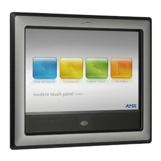
Modero panels are factory setup with specific demo touch panel pages. The first splash screen that appears indicates the panel is receiving power, beginning to load firmware, and preparing to display the default touch panel pages. When the panel is ready, the AMX Splash Screen is replaced by the Initial Panel Page (FIG. 65). AMX Splash Screen... -
Page 92: Testing Your Calibration
Panel Calibration The request to touch the crosshairs is the first on-screen message Calibration successful is the second on-screen message that appears after the calibration process is completed On-screen crosshairs used for calibration of the touch device FIG. 67 Touch Panel Calibration Screens After the "Calibration Successful."... -
Page 93: Configuring Communication
G4 panel is powered-up. The panel will not detect a USB connection of this type until after the unit cycles power. Before commencing, verify you are using the latest NetLinx Master and Modero panel firmware. Verify you are using the latest versions of AMX’s NetLinx Studio and TPDesign4 programs. Modero Setup and System Connection Press the grey Front Setup Access button for 3 seconds to open the Setup page (FIG. - Page 94 Configuring Communication FIG. 69 Protected Setup page Press the on-screen Reboot button to restart the panel and incorporate any changes. Before continuing, open NetLinx Studio. This program assists in developing a System Number, Master IP/URL, and Master Port number. Refer to your NetLinx Master’s instruction manuals for more information.
-
Page 95: Configuring And Using Usb With A Virtual Master
Step 2: Confirming the Installation of the USB Driver on the PC The first time each AMX touch panel is connected to the PC it is detected as a new hardware device and the USBLAN driver becomes associated with it (panel specific). Each time thereafter the panel is "recognized" as a unique USBLAN device and the association to the driver is done in the background. - Page 96 Configuring Communication After the panel powers-up, press and hold the grey Front Setup Access button (for 3 seconds) to continue with the setup process and proceed to the Setup page. Select Protected Setup > System Settings (located on the lower-left) to open the System Settings page (FIG. 71). No connection is established until the Virtual Master becomes active within Studio...
-
Page 97: Step 3: Confirm And View The Current Amx Usb Device Connections
The previous version of the AMX USBLAN driver showed a USB connection icon in the system tray when a panel was connected. The new version of the driver does not show an icon in the System Tray. A Virtual NetLinx Master (VNM) is used when the target panel is not connected to a physical NetLinx Master. -
Page 98: Step 4: Using A Usb To Configure A Virtual Master (Using Netlinx Studio)
Verify the panel has been configured to communicate via USB within the System Settings page and that the USB driver has been properly configured. Refer to the previous section for more information. Launch NetLinx Studio 2.x (default location is Start > Programs > AMX Control Disc > NetLinx Studio 2 > NetLinx Studio 2). -
Page 99: Step 5: Confirm And View The Current Amx Usb Device Connections
(turning the System Connection icon green). Step 5: Confirm and View the current AMX USB device connections Use the CC-USB Type-A to Mini-B 5-wire programming cable (FG10-5965) to provide communication between the mini-USB Program port on the touch panel and the PC. -
Page 100: Wireless Settings Page - Wireless Access Overview
Ethernet Communication from the panel can be direct (using an Ethernet cable) or indirect (through the optional NXA- PCI80211G AMX Wireless Card (FG2255-04) communicating to a Wireless Access Point such as the NXA- WAP200G). In determining the Ethernet method of communication, the panel will always default first to the direct Ethernet communication. -
Page 101: Wireless Communication Using A Dhcp Address
Configuring Communication Wireless communication using a DHCP Address Press the Protected Setup button (located on the lower-left of the panel page) to open the Protected Setup page and display an on-screen keypad. Enter 1988 into the Keypad’s password field and press Done when finished. Press the Wireless Settings button (located on the lower-left) to open the Wireless Settings page. -
Page 102: Step 2: Configuring The Card's Wireless Security Settings
Configuring Communication Toggle the DHCP/Static field (from the IP Settings section) until the choice cycles to Static. The IP Address, Subnet Mask, and Gateway fields then become user-editable (red). Press the IP Address field to open a Keyboard and enter the Static IP Address (provided by your System Administrator). -
Page 103: Configuring The Modero's Wireless Card For Secured Access To A Wap200G
The card should be given the SSID used by the target WAP. If this field is left blank, the unit will attempt to connect to the first available WAP. By default, all WAP200Gs use AMX as their assigned SSID value. - Page 104 You must maintain the same case when entering the SSID information. ABC is not the same as Abc. The alpha-numeric string is by default AMX but can later be changed to any 32-character entry. This string must be duplicated within the Network Name (SSID) field on the WAP. ...
- Page 105 Configuring Communication The code key generator on Modero panels use the same key generation formula. Therefore, this same Passphrase generates identical keys when done on any Modero because they all use the same Modero-specific generator. The Passphrase generator is case sensitive. Within this on-screen WEP Passphrase keyboard (FIG.
-
Page 106: Configuring Multiple Wireless Moderos To Communicate To A Target Wap200G
Configuring Communication Press the Back button to navigate to the Protected Setup page and press the on-screen Reboot button to both save any changes and restart the panel. Remember that you will need to navigate to the System Settings page and configure the connection to a target Master. -
Page 107: Ip Settings Section - Configuring A Static Ip Address Over Ethernet
Configuring Communication DHCP will register the unique MAC Address (factory assigned) on the panel and once the communication setup process is complete, reserve an IP Address, Subnet Mask, and Gateway values from the DHCP Server. Press the optional Host Name field to open a Keyboard and enter the Host Name information. Press Done after you are finished assigning the alpha-numeric string of the host name. -
Page 108: Step 3: Configuring The Ethernet Connection Type
Configuring Communication • AUTO is used to instruct the Modero to search for a Master that uses the same System Number (assigned within the Master Connection section) and resides on the same Subnet as itself. In this case, the Master has its UDP feature enabled. -
Page 109: Master Connection - Virtual Master Communication Over Ethernet
Verify the panel has been configured to communicate either through an Ethernet cable (connected from either the panel to a valid Ethernet Hub) or wireless to the Wireless Access Point. Launch NetLinx Studio 2.x (default location is Start > Programs > AMX Control Disc > NetLinx Studio 2 > NetLinx Studio 2). -
Page 110: Master Connection Section - Netlinx Master Ethernet Ip Address - Url Mode
Master (virtual or not). A Virtual Master system value can be set within the active AMX software applications such as: NetLinx Studio, TPD4, or IREdit. Press the Master IP/URL field to open a Keyboard and enter the IP Address of the PC used as the Virtual Master. -
Page 111: Master Connection Section - Netlinx Master Ethernet Ip Address - Listen Mode
Configuring Communication Press the Back button to open the Protected Setup page. Press the on-screen Reboot button to both save any changes and restart the panel. Master Connection section - NetLinx Master Ethernet IP Address - Listen Mode In this mode, you must add the Modero panel IP Address into the URL List of the Master (using NetLinx Studio). This mode sets the Modero panel to "listen"... -
Page 112: Using G4 Web Control To Interact With A G4 Panel
Refer to the G4 Web Control Settings section on page 140 for more detailed field information. Verify your NetLinx Master (ME260/64 or NI-Series) has been installed with the latest firmware KIT file from www.amx.com. Refer to your NetLinx Master Instruction Manual for more detailed information on the use of the new web-based NetLinx Security. -
Page 113: Using Your Netlinx Master To Control The G4 Panels
Refer to your particular NetLinx Master’s instruction manual for detailed information on how to download the latest firmware from www.amx.com. This firmware build enables SSL certificate identification and encryption, HTTPS communication, ICSP data encryption, and disables the ability to alter the Master security properties via a TELNET session. - Page 114 Both HTTP and HTTPS Ports are enabled by default (via the Manage System > Server page). If the Master has been previously configured for secured communication, click OK to accept the AMX SSL certificate (if SSL is enabled) and then enter a valid username and password into the fields within the Login dialog.
- Page 115 Configuring Communication Click Yes from the Security Alert popup window to agree to the installation of the G4 WebControl application on your computer. This application contains the necessary Active X and VNC client applications necessary to properly view and control the panel pages from your computer. The G4 Web Control application is sent by the panel to the computer that is used for communication.
- Page 116 Configuring Communication VG Series Modero Touch Panels...
-
Page 117: Upgrading Modero Firmware
Upgrading Modero Firmware Upgrading Modero Firmware Overview Before beginning the Upgrade process: Setup and configure your NetLinx Master. Refer to your particular NetLinx Master instruction manual for detailed setup procedures. Calibrate and prepare the communication pages on the Modero panel for use. Refer to the Panel Calibration section on page 77. -
Page 118: Step 2: Prepare Netlinx Studio For Communication Via The Usb Port
Navigate back to the System Settings page. Step 2: Prepare NetLinx Studio for communication via the USB port Launch NetLinx Studio 2.x (default location is Start > Programs > AMX Control Disc > NetLinx Studio 2 > NetLinx Studio 2). -
Page 119: Step 3: Confirm And Upgrade The Firmware Via The Usb Port
If the panel firmware being used is not current, download the latest Kit file by first logging in to www.amx.com and then navigate to Tech Center > Firmware Files and from within the Modero section of the web page locate your Modero panel. - Page 120 Upgrading Modero Firmware FIG. 92 Using USB for a Virtual Master transfer Select the panel’s KIT file from the Files section. Enter the Device value associated with the panel and the System number associated with the Master (listed in the OnLine Tree tab of the Workspace window).
-
Page 121: Upgrading The Modero Firmware Via An Ip Address
Note the IP Address and Gateway information. Launch NetLinx Studio 2.x (default location is Start > Programs > AMX Control Disc > NetLinx Studio 2 > NetLinx Studio 2). Select Settings > Master Communication Settings from the Main menu to open the Master Communication Settings dialog (FIG. -
Page 122: Step 2: Prepare The Panel For Communication Via An Ip
Master (virtual or not). A Virtual Master system value can be set within the active AMX software applications such as: NetLinx Studio, TPD4, or IREdit. Press the red Master IP/URL field to open a Keyboard and enter the NetLinx Master’s IP Address (obtained from the Diagnostics - Networking Address dialog of the NetLinx Studio application). - Page 123 The panel firmware is shown on the right of the listed panel. If the panel firmware being used is not current, download the latest Kit file by first logging in to www.amx.com and then navigate to Tech Center > Firmware Files and from within the Modero section of the web page locate your Modero panel.
-
Page 124: Upgrading Accessory Devices Via An Ip Address
Upgrading Modero Firmware Click the Reboot Device checkbox. This causes the touch panel to reboot after the firmware update process is complete. The reboot of the panel can take up 30 seconds after the firmware process has finished. Click Send to begin the transfer. The file transfer progress is indicated on the bottom-right of the dialog (FIG. 95). Click Close (after the panel reboots) to return to the main program. -
Page 125: Step 2: Upgrade The Nxa-Base/B Firmware Via An Ip
10001. The NXA-BASE/B will not appear on the system listing. Locate the latest Kit file by first logging in to www.amx.com and then navigate to Tech Center > Firmware Files and from within the Modero section of the web page locate the Modero Battery Base section of the website. -
Page 126: Upgrading The Nxa-Rgb And Nxa-Avb/Rgb Firmware
Upgrading Modero Firmware Selected Battery Base Firmware file Description field for selected Firmware download status Device value and System number must match the values listed in the Workspace window FIG. 98 Send to NetLinx Device dialog (showing NXA-BASE/B firmware update via IP) Select the battery base’s KIT file (ending in VXX.kit) from the Files section (FIG. - Page 127 Upgrading Modero Firmware Firmware version of the NXA-RGB card Firmware version of the NXA-AVB/RGB Incoming signal shown in the background FIG. 99 RGB Adjustment page (showing the default values) Follow the procedures outlined within the Step 2: Upgrade the NXA-BASE/B firmware via an IP section on page 111.
- Page 128 Upgrading Modero Firmware VG Series Modero Touch Panels...
-
Page 129: Firmware Pages And Descriptions
Firmware Pages and Descriptions Firmware Pages and Descriptions Overview This section describes each firmware page and their specific functional elements. Setup Navigation Buttons The Setup Navigation Buttons (FIG. 100) appear on-screen when the Setup page is active. Modero Setup Navigation Buttons FIG. -
Page 130: Setup Page
Firmware Pages and Descriptions Setup Navigation Button Elements (Cont.) Battery Base: Press the Battery Base button to access the Battery Base page, where you can modify and monitor NXT-BP Modero Power Pack parameters. • This button only appears when a Modero Table Top panel (NXT) is connected to an NXA-BASE/B battery base. -
Page 131: Panel Information Page
Displays the model of the Modero panel being used. Firmware Version: Displays the G4 firmware version being used by the panel. • Verify you have the latest version from www.amx.com. Setup Port: Displays the setup port information/value being used by the panel. -
Page 132: Project Information Page
Firmware Pages and Descriptions Panel Information Page Elements (Cont.) High Level: Displays the high level (level count) value being used by the panel. Serial Number: Displays the specific serial number value assigned to the panel. Setup Pages Version: Displays the type and version of the Setup pages being used by the panel. Screen Width: Displays the pixel width being used to display the incoming video signal on the Modero panel. -
Page 133: Time & Date Settings Page
Firmware Pages and Descriptions Project Information Page Elements (Cont.) File Revision: Displays the revision number of the file. Dealer ID: Displays the dealer ID number (unique to every dealer and entered in TPD4). Job Name: Displays the job name. Sales Order: Displays the sales order information. -
Page 134: Audio Settings Page
Firmware Pages and Descriptions Time & Date Settings Page Elements (Cont.) Set Date/Time: This section provides a user with both UP/DN arrow buttons to alter the Master’s calendar date and time. The blue circle indicates which field is currently selected. •... -
Page 135: Supported Sampling Rates For Wav
Firmware Pages and Descriptions Audio Settings Page Elements (Cont.) Default Panel Sounds: Sets the Modero panel to play either the default Button Hit sound (when you touch an active button) and/or the default Button Miss sound (when you touch a non-active button or any area outside of the active button). -
Page 136: Protected Setup Page
Firmware Pages and Descriptions Protected Setup Page This button opens the Protected Setup page which centers around the properties used by the panel to properly communicate with the NetLinx Master. Refer to both the Protected Setup Navigation Buttons section on page 132 and the Protected Setup Page section on page 133 for more detailed information. -
Page 137: Video - Rgb Settings Page
Firmware Pages and Descriptions Video Settings Page Elements (Cont.) Format: Allows you to press this blue field and cycle through a choice of available video formats (NTSC, PAL, SECAM, or Auto detect). • Default = Auto. Brightness: Use the UP/DN buttons to alter the brightness level of the incoming signal. •... - Page 138 Firmware Pages and Descriptions RGB Settings Page Elements (Cont.) Cable Variance: Allows you cycle through a choice of available cable compensation parameters (Short, Medium, and Long). • This field adjusts the cable compensation for any signal degradation over a selected cable length.
- Page 139 30 nano-seconds @ 200ft, and that can be more than enough to cause the image to appear "off" or blurry. For this reason, AMX recommends using the Belden Brilliance VideoTwist 7987 cable. Although this cable is not CAT5 compliant, it is designed to control skew between the red, green, and blue video signals.
-
Page 140: Adjusting The Incoming Signal On The Rgb Settings Page
Firmware Pages and Descriptions RGB Settings Page Elements (Cont.) Full Screen Edit Mode: Pressing the incoming signal area (FIG. 109) activates the Full Screen Edit mode. The on- screen popup provides each field with UP/DN buttons to more accurately adjust the values for all of the above mentioned RGB parameter fields. - Page 141 Firmware Pages and Descriptions Use the UP/DN Brightness buttons (from the RGB Brightness popup dialog) to adjust either the overall or individual Red, Green, and Blue brightness of the incoming image/video. The All Brightness bargraph gives a visual representation of the overall brightness level and cycles through an entire turn. Use the UP/DN Contrast buttons (from the RGB Contrast popup dialog) to adjust the overall or individual Red, Green, and Blue contrast of the incoming image/video.
-
Page 142: Video - Streaming Settings Page
Firmware Pages and Descriptions Video - Streaming Settings Page The Streaming Settings page (FIG. 108) adjusts the Video properties of the incoming MPEG video streaming from the external content server. Refer to the Displaying Stream Content section on page 153 for the procedures used to configure the TPD4 touch panel pages and media stream source (using MAX-CSE for example purposes). - Page 143 Firmware Pages and Descriptions Streaming Settings Page Elements (Cont.) Resolution This relates to the display size/resolution used by the incoming video stream. • Available resolutions: D1 (default) or SIF: • D1 is a resolution standard. In the NTSC system, "Full D1" means 720x480 pixels @ 30 fps, and in PAL systems, full D1 is 720x576 @ 24 fps.
-
Page 144: Battery Base Page
Firmware Pages and Descriptions Streaming Settings Page Elements (Cont.) Contrast: Use the UP/DN buttons to alter the contrast level of the incoming signal. • Range = 0 - 255, default = 128. Saturation: Use the UP/DN buttons to alter the color saturation level of the incoming signal. •... - Page 145 Firmware Pages and Descriptions Battery Base Page Elements (Cont.) Very Low Battery Warning: The Very Low Battery Warning UP/DN buttons alter the time value (in minutes) available on the battery (for use) before the panel displays a very low battery warning. This indicates a near-term panel shutdown.
-
Page 146: Protected Setup Navigation Buttons
Firmware Pages and Descriptions Protected Setup Navigation Buttons The Protected Setup Navigation Buttons (FIG. 114) appear on the left of the panel screen when the Protected Setup page is currently active. Modero Protected Setup Navigation Buttons FIG. 114 Protected Setup Navigation Buttons These Navigation Buttons are specific to these Modero panels and include the panel specific elements described in the following table: Protected Setup Navigation Button Elements... -
Page 147: Protected Setup Page
Firmware Pages and Descriptions Protected Setup Page The Protected Setup page (FIG. 115) centers around the properties used by the panel to properly communicate with the NetLinx Master. Enter the factory default password (1988) into the password keypad to access this page. Provides access to the panel firmware pages by enabling the grey front setup access button:... - Page 148 • The Remove User Pages button allows you remove all current TPD4 touch panel pages currently on the panel (including the pre-installed AMX Demo pages). - Pressing this button launches a Confirmation dialog which asks you to confirm your selection.
-
Page 149: Security Settings
The correct case must be followed with the username: "AMX" or "Amx" will not work. For more information on configuring AMX devices for a secure environment, please refer to the guide Security Profiles: Configuring AMX Devices For Installation Into a Secure Environment, available at www.amx.com. -
Page 150: System Settings Page
Sets the speed of the Ethernet connection to the panel. • Choices are: Auto, 10 Half Duplex, 10 Full Duplex, 100 Half Duplex, or 100 Full Duplex. MAC Address Displays a read-only field that is factory set by AMX for the built-in Ethernet interface. VG Series Modero Touch Panels... -
Page 151: Sensor Settings Page
Firmware Pages and Descriptions System Settings Page Elements (Cont.) Master Connection (Cont.): Type Sets the NetLinx Master to communicate with the panel via either USB or Ethernet. This is based on the cable connection from the rear. ICSNet is not a supported option on this panel. •... - Page 152 Firmware Pages and Descriptions A light level value between the Minimum and Maximum DIM Mode values delivers an average light level. The DIM mode Min Level can never exceed the DIM Mode Max Level. The elements of the Sensor Settings page are described in the table below: Sensor Settings Page Elements Back: Saves the changes and returns you to the previously active touch panel page.
-
Page 153: Using The Automated Brightness Control Feature (Dim Mode)
Firmware Pages and Descriptions Sensor Settings Page Elements (Cont.) Dim Mode Minimum Allows you to alter the sensitivity of the Modero panel light sensor: Brightness: • Toggle the Enable/Enabled button to either active/inactive the DIM Mode feature: - Enable - activates this feature. Once active (by receiving a value below the Dim Mode Min Level value), the current light level ramps to the DIM Mode value within a few seconds. -
Page 154: Calibration Page
Firmware Pages and Descriptions Calibration Page This page (FIG. 119) allows you to calibrate the input touch device (touch panel) using the pre-selected touch driver. Press and hold the grey Front Setup Access button (below the Modero LCD) for 6 seconds to access the Calibration page. - Page 155 Firmware Pages and Descriptions G4 Web Control Page Elements Back: Saves the changes and returns you to the previously active touch panel page. Connection Status icon: This visual display of the connection status allows the user to have a current visual update of the panel’s connection status regardless of what page is currently active.
-
Page 156: Other Settings Slide-Out Menu
Firmware Pages and Descriptions Other Settings Slide-Out Menu Pressing the Other Settings button causes an option men to slide outwards from the Protected Setup buttons (FIG. 122). This option menu contains buttons to access the Cache Settings and Password Settings pages. Select any button to open its page. -
Page 157: Setting The Image Cache
Firmware Pages and Descriptions Cache Settings Page Elements Back: Saves all changes and returns to the previous page. Connection Status icon: The icon in the upper-right corner of each Setup page shows online/offline state of the panel to the master. •... -
Page 158: Clearing The Image Cache
Firmware Pages and Descriptions Press the Enable button to turn on image caching. The button appears illuminated when enabled. Select the Up and Down arrows for the field Flash Cache Size to increase or reduce the amount of Flash memory used; the maximum amount of flash that can be allocated for caching is 75% of available flash. -
Page 159: Panel Connection Logs Page Elements
Firmware Pages and Descriptions Panel Connection Logs The options on the Panel Connection Logs page (FIG. 126) allow you to view and track the connection history of the panel. FIG. 126 Panel Connection Logs page Features on this page include: Panel Connection Logs Page Elements Back: Saves all changes and returns to the previous page. -
Page 160: Panel Statistics Page Elements
Firmware Pages and Descriptions Panel Statistics The options on the Panel Statistics page (FIG. 127) allow you to track the connection status for the panel. The Panel Statistics page tracks ICSP messages, Blink messages, Ethernet connection statistics, and Wireless connection statistics. FIG. -
Page 161: Checking The Panel Statistics
Firmware Pages and Descriptions Checking the Panel Statistics Press the Tools button in the Protected Setup Navigation Buttons section. This opens the Tools menu. Within the Tools menu, press the Panel Statistics button. All connection statistics are contained on this page, e.g., Received, Processed, and Dropped ICSP Messages. -
Page 162: Using The Connection Utility
Firmware Pages and Descriptions Connection Utility Popup Window Elements (Cont.) Wireless Information WAP MAC The MAC Address for the WAP currently in use. If the MAC Address changes, it means the panel has switched/roamed to a different access point. This can be used to determine coverage for each access point and help isolate "brown"... - Page 163 Firmware Pages and Descriptions Wireless Settings Page Elements Back: Saves the changes and returns you to the previously active touch panel page. Connection Status icon: This visual display of the connection status allows the user to have a current visual update of the panel’s connection status regardless of what page is currently active.
- Page 164 Wireless Access Point, it comes back with 1a:2b:3c:4d:etc. Entering the same apple in the Passphrase generator of any Modero panel generates a different key: a1:b2:c3:d4:etc. Only AMX Modero panels generate the same Current Key by using a unique Passphrase key generation technology. A Current Key string, when generated anywhere else, will not match those created on the Modero panels.
- Page 165 Firmware Pages and Descriptions Wireless Settings Page Elements (Cont.) Wireless Settings (Cont.): Current Key Displays the current WEP key in use. Keys may also be examined by touching the key buttons and noting the keyboard initialization text. • When working with a single panel and a single WAP, it is recommended that you manually enter the Current Key from the WAP into the selected WEP Key.
- Page 166 Firmware Pages and Descriptions VG Series Modero Touch Panels...
-
Page 167: Displaying Stream Content
Displaying Stream Content Displaying Stream Content Overview The current build of Modero firmware currently supports the display of both MPEG-2 and MPEG-4 media streams via the TPDesign touch panel pages. These incoming media signals can utilize either a UDP or RTP Transport protocol. For the purposes of these instructions, we will be setting up a Modero touch panel to display an incoming media stream sent from a MAX Video Encoder. -
Page 168: Requirements For Receiving Streamed Content
Verify you have installed the latest version of TPDesign4 on your PC. Updates are available from the www.amx.com > Tech Center > Application Files > Touch Panel Design Tools section of the website. This application is needed to create the necessary page (popup page) used to display the incoming MPEG audio/ video stream, identify the IP of the source MAX-CSE, and define the target audio/video ports on the panel. -
Page 169: Step 2: Configuring The Max-Cse For Communication
Displaying Stream Content Press the Protected Setup button (located on the lower-left of the panel page) to open the Protected Setup page and display an on-screen keypad. Enter 1988 into the Keypad’s password field and press Done when finished. Press the System Settings button (located on the Protected Setup page) to open the System Settings page and obtain the IP information from the IP Address field (FIG. - Page 170 Displaying Stream Content Encoding Presets (including Custom) Video Encoding Parameters Audio Encoding Parameters Stream Destination Communication/Connection Parameters (use even port values) FIG. 132 Stream Profiles page From the Profile field, click on the drop-down arrow and from the available list, choose the desired encoder setting which conforms to the available data throughput on your network.
-
Page 171: Step 3: Configuring The Max-Cse Audio/Video Inputs
Displaying Stream Content These port values must use even numbers FIG. 133 Stream Profiles page (showing a sample configuration) Click the Apply button to save the encoding profiles to the MAX-CSE. If using RTP, both the Target Port and Target Audio Port must be different and should use even numbers. -
Page 172: Step 4: Setup A Streaming Page Within Tpdesign4
Click the Apply button to save the encoding profiles to the MAX-CSE. Step 4: Setup a streaming page within TPDesign4 Launch TPDesign4 (default location is Start > Programs > AMX Control Disc > TPDesign4 > TPDesign4). Refer to the TPDesign4 Instruction Manual for more detailed instructions of these procedures. - Page 173 Displaying Stream Content Button Draw and Selection tools Currently active button Button Properties Control window (displays information for the currently active/selected button) FIG. 136 Button Properties tab Click the States tab of the Button Properties Control window to show a list of all states associated with the selected button.
-
Page 174: Step 5: Establishing The Final Connection Between The Two Units
Displaying Stream Content Modero doesn’t require that an audio port be entered within the Streaming Source field because the firmware already assumes the audio port value to be 2 greater than the value set for the video port. Create buttons on both this project’s main page and within this Video page which can allow the user to navigate between both pages. -
Page 175: Programming
Programming Programming Overview You can program the touch panel, using the commands in this section, to perform a wide variety of operations using Send_Commands and variable text commands. A device must first be defined in the NetLinx programming language with values for the Device: Port: System (in all programming examples - Panel is used in place of these values and represents all Modero panels). -
Page 176: Dpg
Programming Page Commands (Cont.) @DPG Delete a specific popup page from specified popup group if it exists. Syntax: "'@DPG-<popup page name>;<popup group name>'" Variable: popup page name = 1 - 50 ASCII characters. Name of the popup page. popup group name = 1 - 50 ASCII characters. Name of the popup group. Example: SEND_COMMAND Panel,"'@DPG-Popup1;Group1'"... -
Page 177: Ppa
Programming Page Commands (Cont.) @PPA Close all popups on a specified page. If the page name is empty, the current page is used. Same as the ’Clear Page’ command in TPDesign4. Syntax: "'@PPA-<page name>'" Variable: page name = 1 - 50 ASCII characters. Name of the page the popup is displayed On. Example: SEND_COMMAND Panel,"'@PPA-Page1'"... -
Page 178: Ppm
Programming Page Commands (Cont.) @PPM Set the modality of a specific popup page to Modal or NonModal. A Modal popup page, when active, only allows you to use the buttons and features on that popup page. All other buttons on the panel page are inactivated. Syntax: "'@PPM-<popup page name>;<mode>'"... -
Page 179: Pse
Programming Page Commands (Cont.) @PSE Set the show effect for the specified popup page to the named show effect. Syntax: "'@PSE-<popup page name>;<show effect name>'" Variable: popup page name = 1 - 50 ASCII characters. Name of the page the popup is displayed On. show effect name = Refers to the popup effect name being used. -
Page 180: Programming Numbers
Programming Page Commands (Cont.) PPOG Toggle a specific popup page on either a specified page or the current page. If the page name is empty, the current page is used (see example 2). Toggling refers to the activating/deactivating (On/Off) of a popup page. This command works in the same way as the ’Toggle Popup’... - Page 181 Programming RGB Values for all 88 Basic Colors (Cont.) Index No. Name Green Blue Very Light Lime Light Lime Lime Medium Lime Dark Lime Very Dark Lime Very Light Green Light Green Green Medium Green Dark Green Very Dark Green Very Light Mint Light Mint Mint...
-
Page 182: Font Styles And Id Numbers
The TPDesign4 Touch Panel Design program has pre-set border styles that are user selectable. TPD4 border styles can ONLY be changed by using the name. TPD4 Border Styles by Name Border styles Border styles None Diamond 55 AMX Elite -L Diamond 65 AMX Elite -M Diamond 75 AMX Elite -S Double Bevel -L Bevel -L... - Page 183 Programming TPD4 Border Styles by Name (Cont.) Border styles Border styles Circle 65 Menu Bottom Rounded 25 Circle 75 Menu Bottom Rounded 35 Circle 85 Menu Bottom Rounded 45 Circle 95 Menu Bottom Rounded 55 Circle 105 Menu Bottom Rounded 65 Circle 115 Menu Bottom Rounded 75 Circle 125...
-
Page 184: Button Commands
Programming TPD4 Border Styles by Name (Cont.) Border styles Border styles Menu Rounded Spacer - Vertical Windows Style Popup Menu Rounded Spacer - Horizontal Windows Style Popup (Status Bar) Menu Top Rounded 55 Menu Top Rounded 65 "^" Button Commands These Button Commands are used in NetLinx Studio and are case insensitive. -
Page 185: Bat
Programming "^" Button Commands (Cont.) ^BAT Append non-Unicode text. Syntax: "'^BAT-<vt addr range>,<button states range>,<new text>'" Variable: variable text address range = 1 - 4000. button states range = 1 - 256 for multi-state buttons (0 = All states, for General buttons 1 = Off state and 2 = On state). -
Page 186: Bcf
Programming "^" Button Commands (Cont.) ^BCF Set the fill color to the specified color. Only if the specified fill color is not the same as the current color. Note: Color can be assigned by color name (without spaces), number or R,G,B value (RRGGBB or RRGGBBAA). -
Page 187: Bfb
Programming "^" Button Commands (Cont.) ^BFB Set the feedback type of the button. ONLY works on General-type buttons. Syntax: "'^BFB-<vt addr range>,<feedback type>'" Variable: variable text address range = 1 - 4000. feedback type = (None, Channel, Invert, On (Always on), Momentary, and Blink). Example: SEND_COMMAND Panel,"'^BFB-500,Momentary'"... -
Page 188: Bmc
Programming "^" Button Commands (Cont.) ^BMC Button copy command. Copy attributes of the source button to all the destination buttons. Note that the source is a single button state. Each state must be copied as a separate command. The <codes> section represents what attributes will be copied. All codes are 2 char pairs that can be separated by comma, space, percent or just ran together. -
Page 189: Bmf
Programming "^" Button Commands (Cont.) ^BMF Set any/all button parameters by sending embedded codes and data. Syntax: "'^BMF-<vt addr range>,<button states range>,<data>'" Variables: variable text address char array = 1 - 4000. button states range = 1 - 256 for multi-state buttons (0 = All states, for General buttons 1 = Off state and 2 = On state). -
Page 190: Bmi
Programming "^" Button Commands (Cont.) ^BMF ’’%GU<bargraph ramp up>’ = Set the bargraph ramp up time in intervals of 1/10 second. (Cont.) ’%GD<bargraph ramp down>’ = Set the bargraph ramp down time in 1/10 second. ’%GG<bargraph drag increment> = Set the bargraph drag increment. Refer to the ^GDI command on page 182 for more information. -
Page 191: Bml
Programming "^" Button Commands (Cont.) ^BML Set the maximum length of the text area button. If this value is set to zero (0) there is no max length. The maximum length available is 2000. This is only for a Text area input button and not for a Text area input masking button. -
Page 192: Bop
Sets the border by number (#10) to those buttons with the variable text range of 500-504 & 510-515. SEND_COMMAND Panel,"'^BOR-500.504&510,AMX Elite -M'" Sets the border by name (AMX Elite) to those buttons with the variable text range of 500-504 & 510-515. The border style is available through the TPDesign4 border-style drop-down list. Refer to theTPD4 Border Styles by Name table on page 168 for more information. -
Page 193: Bpp
Programming "^" Button Commands (Cont.) ^BPP Set or clear the protected page flip flag of a button. Zero clears the flag. Syntax: "'^BPP-<vt addr range>,<protected page flip flag value>'" Variable: variable text address range = 1 - 4000. protected page flip flag value range = 0 - 4 (0 clears the flag). Example: SEND_COMMAND Panel,"'^BPP-500,1'"... -
Page 194: Bso
Programming "^" Button Commands (Cont.) ^BSO Set the sound played when a button is pressed. If the sound name is blank the sound is then cleared. If the sound name is not matched, the button sound is not changed. Syntax: "'^BSO-<vt addr range>,<button states range>,<sound name>'"... -
Page 195: Bww
Programming "^" Button Commands (Cont.) ^BWW Set the button word wrap feature to those buttons with a defined address range. By default, word-wrap is Off. Syntax: "'^BWW-<vt addr range>,<button states range>,<word wrap>'" Variable: variable text address range = 1 - 4000. button states range = 1 - 256 for multi-state buttons (0 = All states, for General buttons 1 = Off state and 2 = On state). -
Page 196: Fon
Programming "^" Button Commands (Cont.) ^FON Set a font to a specific Font ID value for those buttons with a defined address range. Font ID numbers are generated by the TPDesign4 programmers report. Syntax: "'^FON-<vt addr range>,<button states range>,<font value>'" Variable: variable text address range = 1 - 4000. -
Page 197: Gll
Programming "^" Button Commands (Cont.) ^GLL Change the bargraph lower limit. Syntax: "'^GLL-<vt addr range>,<bargraph low>'" Variable: variable text address range = 1 - 4000. bargraph limit range = 1 - 65535 (bargraph lower limit range). Example: SEND_COMMAND Panel,"'^GLL-500,150'" Changes the bargraph lower limit to 150. ^GRD Change the bargraph ramp-down time in 1/10th of a second. -
Page 198: Gsn
Programming "^" Button Commands (Cont.) ^GSN Change the bargraph slider name or joystick cursor name. Slider names and cursor names can be found in the TPDesign4 slider name and cursor drop-down list. Syntax: "'^GSN-<vt addr range>,<bargraph slider name>'" Variable: variable text address range = 1 - 4000. bargraph slider name = See table below. -
Page 199: Jsi
Programming "^" Button Commands (Cont.) ^JSI Set icon alignment using a numeric keypad layout for those buttons with a defined address range. The alignment of 0 is followed by ',<left>,<top>'. The left and top coordinates are relative to the upper left corner of the button. -
Page 200: Mdc
Programming "^" Button Commands (Cont.) ^MDC Turn On the ’Mouse double-click’ feature for the virtual PC. Syntax: "'^MDC'" Example: SEND COMMAND Panel,"'^MDC'" Sets the mouse double-click for use with the virtual PC. ^SAV Saves the current configuration values. ^SHO Show or hide a button with a set variable text range. Syntax: "'^SHO-<vt addr range>,<command value>'"... -
Page 201: Tef
Programming "^" Button Commands (Cont.) ^TEF Set the text effect. The Text Effect is specified by name and can be found in TPD4. Syntax: "'^TEF-<vt addr range>,<button states range>,<text effect name>'" Variable: variable text address range = 1 - 4000. button states range = 1 - 256 for multi-state buttons (0 = All states, for General buttons 1 = Off state and 2 = On state). -
Page 202: Text Effect Names
Programming Text Effect Names The following is a listing of text effects names. This list is associated with the ^TEF command on page 187. Text Effects • Glow -S • Hard Drop Shadow 6 • Glow -M • Hard Drop Shadow 7 •... -
Page 203: Bbv
Programming Send_String 0,"'VALUE2 =',ITOA(CUSTOM.VALUE2)" Send_String 0,"'VALUE3 =',ITOA(CUSTOM.VALUE3)" Send_String 0,"'TEXT =',CUSTOM.TEXT" Send_String 0,"'TEXT LENGTH =',ITOA(LENGTH_STRING(CUSTOM.TEXT))" All custom events have the following 6 fields: Custom Event Fields Field Description Uint Flag 0 means text is a standard string, 1 means Unicode encoded string slong value1 button state number slong value2... -
Page 204: Bcf
Programming Button Query Commands (Cont.) ?BCF Get the current fill color. Syntax: "'?BCF-<vt addr range>,<button states range>'" Variable: variable text address range = 1 - 4000. button states range = 1 - 256 for multi-state buttons (0 = All states, for General buttons 1 = Off state and 2 = On state). -
Page 205: Bmp
Programming Button Query Commands (Cont.) ?BMP Get the current bitmap name. Syntax: "'?BMP-<vt addr range>,<button states range>'" Variable: variable text address range = 1 - 4000. button states range = 1 - 256 for multi-state buttons (0 = All states, for General buttons 1 = Off state and 2 = On state). -
Page 206: Brd
Programming Button Query Commands (Cont.) ?BRD Get the current border name. Syntax: "'?BRD-<vt addr range>,<button states range>'" Variable: variable text address range = 1 - 4000. button states range = 1 - 256 for multi-state buttons (0 = All states, for General buttons 1 = Off state and 2 = On state). -
Page 207: Dto
Programming Button Query Commands (Cont.) ?DTO Show the display timeout. Returned in Custom event. Value1=display timeout value (in seconds) ?FBC Get the frame buffer CRC. Returned in Custom event. Value1=CRC32 calculated on the panel's frame buffer ?FON Get the current font index. Syntax: "'?FON-<vt addr range>,<button states range>'"... -
Page 208: Jsb
Programming Button Query Commands (Cont.) ?JSB Get the current bitmap justification. Syntax: "'?JSB-<vt addr range>,<button states range>'" Variable: variable text address range = 1 - 4000. button states range = 1 - 256 for multi-state buttons (0 = All states, for General buttons 1 = Off state and 2 = On state). -
Page 209: Jst
Programming Button Query Commands (Cont.) ?JST Get the current text justification. Syntax: "'?JST-<vt addr range>,<button states range>'" Variable: variable text address range = 1 - 4000. button states range = 1 - 256 for multi-state buttons (0 = All states, for General buttons 1 = Off state and 2 = On state). -
Page 210: Tec
Programming Button Query Commands (Cont.) ?TEC Get the current text effect color. Syntax: "'?TEC-<vt addr range>,<button states range>'" Variable: variable text address range = 1 - 4000. button states range = 1 - 256 for multi-state buttons (0 = All states, for General buttons 1 = Off state and 2 = On state). -
Page 211: Txt
Programming Button Query Commands (Cont.) ?TXT Get the current text information. Syntax: "'?TXT-<vt addr range>,<button states range>,<optional index>'" Variable: variable text address range = 1 - 4000. button states range = 1 - 256 for multi-state buttons (0 = All states, for General buttons 1 = Off state and 2 = On state). -
Page 212: Panel Runtime Operations
Programming Panel Runtime Operations Serial Commands are used in the AXCESSX Terminal Emulator mode. These commands are case insensitive. Panel Runtime Operation Commands ABEEP Output a single beep even if beep is Off. Syntax: "'ABEEP'" Example: SEND COMMAND Panel,"'ABEEP'" Outputs a beep of duration 1 beep even if beep is Off. ADBEEP Output a double beep even if beep is Off. -
Page 213: Akp
Programming Panel Runtime Operation Commands (Cont.) @AKP Pop up the keypad icon and initialize the text string to that specified. Keypad string is set to null on power up and is stored until power is lost. The Prompt Text is optional. Syntax: "'@AKP-<initial text>;<prompt text>'"... -
Page 214: Ekp
Programming Panel Runtime Operation Commands (Cont.) @EKP Extend the Keypad. Pops up the keypad icon and initializes the text string to that specified. The Prompt Text is optional. Syntax: "'@EKP-<initial text>;<prompt text>'" Variables: initial text = 1 - 50 ASCII characters. prompt text = 1 - 50 ASCII characters. -
Page 215: Sou
Programming Panel Runtime Operation Commands (Cont.) @SOU Play a sound file. Syntax: "'@SOU-<sound name>'" Variables: sound name = Name of the sound file. Supported sound file formats are: WAV & MP3. Example: SEND COMMAND Panel,"'@SOU-Music.wav'" Plays the 'Music.wav' file. @TKP Present a telephone keypad. -
Page 216: Input Commands
Programming Input Commands These Send Commands are case insensitive. Input Commands ^CAL Put panel in calibration mode. Syntax: "'^CAL'" Example: SEND COMMAND Panel,"'^CAL'" Puts the panel in calibration mode. ^KPS Set keyboard pass-thru via the RGB card. Syntax: "'^KPS-<passs data>'" Variables: pass data: <blank/empty>... -
Page 217: Slt
Programming Input Commands (Cont.) ^SLT Send a command to a given slot. These commands are directed at the video card subsystems. Slot commands contain a series of name/value pairs separated by commas. These commands are case insensitive. Syntax: "’^SLT-<slot number>,<slot command>’" Variables: slot number = 1 - 3 (each of these options corresponds to an on-board slot position where the related components reside.) -
Page 218: Embedded Codes
Programming Embedded Codes The following is a list of G4 compatible embedded codes: Embedded Codes Decimal numbers Hexidecimal values Virtual keystroke ($08) Backspace ($0D) Enter ($1B) ($80) CTRL key down ($81) ALT key down ($82) Shift key down ($83) ($84) ($85) ($86) ($87) -
Page 219: Panel Setup Commands
Programming Panel Setup Commands These commands are case insensitive. Panel Setup Commands ^MUT Set the panel mute state. Syntax: "'^MUT-<mute state>'" Variable: mute state= 0 = Mute Off and 1 = Mute On. Example: SEND_COMMAND Panel,"'^MUT-1''" Sets the panel’s master volume to mute. @PWD Set the page flip password. -
Page 220: Dynamic Image Commands
Adds a new resource. • The resource name is ’New Image’ • %P (protocol) is an HTTP • %H (host name) is AMX.COM • %A (file path) is Lab/Test_file • %F (file name) is test.jpg. Note that the %%5F in the file path is actually encoded as %5F. -
Page 221: Raf, ^Rmf - Embedded Codes
Programming Dynamic Image Commands (Cont.) ^RMF Modify an existing resource. Modifies any and all resource parameters by sending embedded codes and data. Since the embedded codes are preceded by a '%' character, any '%' character contained in the URL must be escaped with a second '%' character (see example). -
Page 222: Escape Sequences
Y resolution of current panel mode/file Current state Address code Address port Channel code Channel port Level code Level port X Resolution of Current button Y Resolution of Current button Name of Button For instance, http://www.amx.com/img.asp?device=$DV would become http://www.amx.com/img.asp?device=10001. VG Series Modero Touch Panels... -
Page 223: Troubleshooting
• The panel can take a few minutes to detect the connection to the PC. I keep getting a yellow exclamation • Make sure you have installed the latest USB driver for the AMX LAN. point on my USB in the System Tray. - Page 224 • This is due to the graphics controller settings in the firmware. • Update firmware to the latest v2.XX. firmware. • Visit the www.amx.com > Tech Center > Downloadable Files > Firmware Files > Modero panels. Then Download the KIT file to your computer.
- Page 225 • The NXA-BASE/B Battery base should be updated with the latest firmware supply. (part of the Modero firmware KIT file) from www.amx.com. • The base can only charge batteries while the NXT panel is in Sleep Mode. If the panel parameters are set to their highest values, the priority for the power draw becomes the active panel functions and no power is routed to the base for charging.
- Page 226 "graphics hierarchy" errors, etc.… indicating problems with the Compact Flash. • Panel will not boot, or gets stuck on "AMX" splash screen. • Other problems also started after downloading to a new panel or a panel with a TPD4 file that takes up a considerable amount of the available Compact Flash.
-
Page 227: Appendix
Appendix Appendix Text Formatting Codes for Bargraphs/Joysticks Text formatting codes for bargraphs provide a mechanism to allow a portion of a bargraphs text to be dynamically provided information about the current status of the level (multistate and traditional). These codes would be entered into the text field along with any other text. -
Page 228: Input Mask Character Types
Appendix • Force you to use correct type of characters (i.e. numbers vs. characters) • Limit the number of characters in a text area • Suggest proper format with fixed characters • Right to Left • Required or Optional • Change/Force a Case •... -
Page 229: Input Mask Next Field Characters
Appendix Input mask next field characters These characters allow you to specify a list of characters that cause the keyboard to move the focus to the next field when pressed instead of inserting the text into the text area. Input Mask Next Field Char Character Meaning Start Next Field List End Next Field List... -
Page 230: Input Mask Output Examples
(HyperText Transport Protocol) and that the information resides on a host machine named www.amx.com. The image on that host machine is given an assignment (by the program) name of company-info-home.asp (Active Server Page). The exact meaning of this name on the host machine is both protocol dependent and host dependent. - Page 231 Appendix VG Series Modero Touch Panels...
- Page 232 - Schedules and registration for any AMX University course - Travel and hotel information - Your individual certification requirements and progress 3000 RESEARCH DRIVE, RICHARDSON, TX 75082 USA • 800.222.0193 • 469.624.8000 • 469-624-7153 fax • 800.932.6993 technical support • www.amx.com...
Need help?
Do you have a question about the NXD-1200VG and is the answer not in the manual?
Questions and answers