Table of Contents
Advertisement
Quick Links
™
Ashtech
1170 Kifer Road
Sunnyvale, CA USA 94086
Phone and Fax Numbers
•
Main
•
Voice: 408-524-1400
•
Fax: 408-524-1500
•
Sales
•
US: 800-922-2401
•
International: 408-524-1670
•
Fax: 408-524-1500
•
Europe
•
Voice: 44-993-883-533
•
Fax: 44-993-883-977
•
Support
•
US: 800-229-2400
•
International: 408-524-1680
•
Fax: 408-524-1500
•
BBS
•
Direct: 408-524-1527
Internet
•
support@ashtech.com
•
http://www.ashtech.com
Advertisement
Table of Contents

Related Manuals for ashtech GG Surveyor


Summary of Contents for ashtech GG Surveyor
- Page 1 ™ Ashtech 1170 Kifer Road Sunnyvale, CA USA 94086 Phone and Fax Numbers • Main • Voice: 408-524-1400 • Fax: 408-524-1500 • Sales • US: 800-922-2401 • International: 408-524-1670 • Fax: 408-524-1500 • Europe • Voice: 44-993-883-533 • Fax: 44-993-883-977 •...
- Page 2 Part Number: 630199-01, Revision A January, 1998 Trademarks Ashtech® is a registered trademark of Magellan Corp. GG Surveyor , GPS+GLO- NASS, GPS-RTK, REMOTE, EVALUATE, GPS TOPO, WinPRISM, Survey Con- trol Software, Mine Surveyor, and the Ashtech logo are trademarks of Magellan Corp.
- Page 3 Relocate the receiver relative to the equipment which it interferes. • Power the equipment from a different AC receptacle so that this equipment and the interfered equipment are on different branch circuits. If necessary, contact the Ashtech customer service department or an authorized representative for additional advice.
- Page 4 9(C)(1) and (2) of the Commercial Computer Software - Restricted Rights 48 CFR 52.227.19, as applicable. Should you have any questions concerning the License Agreement or the Limited Warranties and Limitation of Liability, please contact in writing: Ashtech, 1170 Kifer Road, Sunnyvale, CA 94086 GG Surveyor GPS+GLONASS Reference Manual...
-
Page 5: Table Of Contents
Chapter 1. Introduction ..........1 Functional Description . - Page 6 Receiver Communications ........21 Input Messages to the GG Surveyor ......21 Output Messages From the GG Surveyor .
- Page 7 Setting Up a Differential Base Station ......45 Setting Up an RTK Base Station ....... . 46 Setting Up a Combined Differential and RTK Base Station .
- Page 8 PPS: 1 PPS Pulse Output ....... . . 100 PRJ: Set Session Logging Information ..... . 101 viii GG Surveyor GPS+GLONASS Reference Manual...
- Page 9 PRT: Port Setting ........101 RCI: Recording Interval .
- Page 10 FST: Fast CPD Mode ........193 GG Surveyor GPS+GLONASS Reference Manual...
- Page 11 INF: CPD Information ........193 MAX: Maximum Age ........194 MOD: CPD Mode .
- Page 12 Ashtech Bulletin Board ........
- Page 13 GG Surveyor ........
- Page 14 GG Surveyor GPS+GLONASS Reference Manual...
- Page 15 Accuracy as Function of Mode ....... 3 Table 1.3: GG Surveyor Receiver Options ......4 Table 2.1: GG Surveyor Front Panel Description .
- Page 16 Typical GPGSN Response Message ..... 144 Table 6.57: Typical GLGSN Response Message ..... 145 GG Surveyor GPS+GLONASS Reference Manual...
- Page 17 Table 6.58: GST Message Structure ....... 146 Table 6.59: Typical GST Response ....... . 147 Table 6.60: GXP Structure.
- Page 18 Table E.1 GPS Product Information.......E-1 xviii GG Surveyor GPS+GLONASS Reference Manual...
-
Page 19: Chapter 1. Introduction
To take advantage of the increased satellite availability, the GG Surveyor has 12 channels for L1 GPS and 12 Channels for L1 GLONASS, providing all-in-view tracking for both constellations. -
Page 20: Technical Specifications
After self-test, the GG Surveyor initializes the battery-backed RAM. If the battery-backed-up RAM fails self-test (due, for example, to a low battery condition), the GG Surveyor clears and reports the loss of stored data, then initializes the 24 channels and begins searching for all satellites within the field of view of the antenna. -
Page 21: Performance Specifications
Performance Specifications One of the most important functions of the GG Surveyor is providing real-time position solutions with accuracy ranging from centimeter level to 100 meters. Table 1.2 summarizes the positioning modes and expected accuracy. Table 1.2: Accuracy as Function of Mode... -
Page 22: Receiver Options
Receiver Options The GG Surveyor has a number of internal receiver options. The commands and features you can use depend upon the options installed in the receiver. For example, if the Photogrammetry option is not installed, you cannot use the $PASHS,TTT command to output event time tags from the serial port. -
Page 23: Position Update Rate
RTCM RTK messages 18 and 19. [B] RTCM Base The [B] option allows the GG Surveyor to be used as a RTCM differential base station capable of outputting real-time differential corrections. The GG Surveyor outputs RTCM-104, Version 2.2 format message types 1, 2, 3, 6, 9, 16, 22, 31, 32, and 34. -
Page 24: E] Event Marker
[E] Event Marker The [E] option allows the output of a time trigger message (TTT) corresponding to the time event created by a trigger signal. The event marker is activated at the rising edge of the trigger signal by default, but can be set to respond to the falling edge on command. -
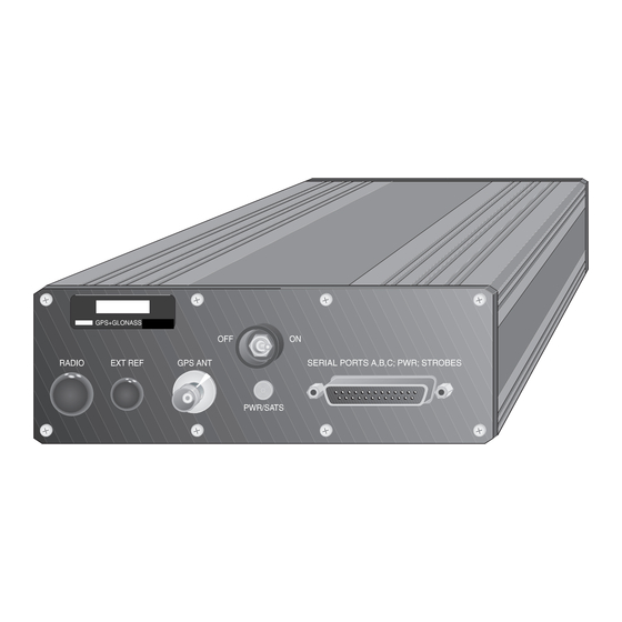
Page 25: Chapter 2. Equipment
Hardware Description The GG Surveyor (Figure 2.1) has four RS-232 input/output (I/O) ports A-D (D is not available to the user), and an L1-band radio-frequency (RF) antenna port. All RS-232 serial ports are capable of two-way communication with external equipment. - Page 26 Table 2.1: GG Surveyor Front Panel Description (continued) Number Component Function Antenna Connector The RF connector is a standard TNC-type female receptacle wired for connection via 50 Ω coaxial cabling to a GPS+GLONASS antenna with an integral LNA. On/Off Switch Turns the receiver on and off.
-
Page 27: Power/Input/Output Connections
Power/Input/Output Connections A DB25 power/input/output connector provides the input power connection, an external LED connection, one-pulse-per-second TTL output, photogrammetry input, and RS-232 I/O (Figure 2.2). Figure 2.2: DB25 Connector J101 Equipment... -
Page 28: Power Requirements
EXT GND 1 EXT PWR 2 EXT GND 2 Power Requirements ± DC voltage: 6 to 15 volts DC, regulated Wattage: 2.8 watts (LNA not included) An on-board battery-backed RAM maintains user setup and data. GG Surveyor GPS+GLONASS Reference Manual... -
Page 29: Rf Interface Connector
The unit may be damaged if the TNC center pin is not isolated from DC ground. Serial/Power Cable The serial/power cable (Figure 2.3) connect the GG Surveyor to the power source, the PC or handheld unit and any peripherals. Figure 2.3: Serial/Power Cable... -
Page 30: Antenna
Antenna The GG Surveyor is designed to work with an antenna-preamplifier that requires five volts and is isolated from DC ground. The gain of the antenna/preamplifier minus the loss of the cable should be between 20 and 30 dB. Connect the antenna cable directly to the antenna connector on the GG Surveyor. -
Page 31: Chapter 3. Standard Operation
This chapter discusses system setup, power-up, command format, serial port configuration, parameter settings and status, and how to perform a static survey. Connection Procedures Components The following components comprise a generic surveying configuration: • GG Surveyor receiver • GPS+GLONASS antenna and antenna extensions • Antenna mounting hardware •... -
Page 32: Communication
(i.e., satellites locked). Communication After you have the GG Surveyor powered and running, you must send it commands in order to receive data and change parameters. Specially designed software which runs on the Husky FS/2 handheld computer can be obtained from Ashtech to perform a variety specific applications. -
Page 33: Initialization
If a response message is not generated, recheck your cable connections and communications parameters, and verify that the receiver is powered on. Initialization It is good practice to reset the receiver prior to operating it for the first time or if a system malfunction occurs. -
Page 34: File Directory
To save the receiver settings, Type: $PASHS,SAV,Y and press <Enter>. For details on these commands and responses, as well as the rest of the GG Surveyor command and response repertoire, refer to Chapter 6, Command/Response Formats. -
Page 35: System Setup
By occupying more than one station, a number of common errors cancel, so that the accuracy can be greatly improved. In order to compute accurate baselines and establish accurate positions on the unknown points, the data collected in the field is post-processed later using a personal computer (PC). -
Page 36: Changing Parameters
Changing Parameters If the default parameters are unacceptable, they may be changed by using either a PC with communication software or a handheld computer with one of the Ashtech interface programs. The GG Surveyor receiver works with most Ashtech interface programs, such as Survey Control, GPS TOPO, and Mine Surveyor. -
Page 37: Downloading Data
Changing parameters using a PC and communication software is done by sending the command that controls the parameter that you wish to change. Chapter 6, Command/ Response Formats lists the complete list of available commands. The most common commands used in static surveying include: •... - Page 38 GG Surveyor GPS+GLONASS Reference Manual...
-
Page 39: Chapter 4. Advanced Operation
CPD (carrier phase differential commands) All command messages (set or query) can be in upper or lower case followed by <Enter>. A valid set command, if this command is successfully executed, causes the GG Surveyor to return the $PASHR,ACK*3D, "acknowledged" response message. Valid query commands are acknowledged by return of the requested information. -
Page 40: Serial Port Configuration
$PASHS,RST (reset to defaults) command, the GG Surveyor defaults to 9600 baud for all RS-232 serial ports. The baud rates between the GG Surveyor and the interfacing equipment must be the same for the port and the device connected to the port. -
Page 41: Figure 4.1: $Pashr,Par Default Response Message
Figure 4.1 shows a typical response message for the general receiver parameters default values of the query command $PASHQ,PAR. See “PAR: Query Receiver Parameters” on page 94 for more information. SPDA:5 SPDB:5 SPDC:5 SPDD:5 GPS:YYYYYYYYYYYYYYYYYYYYYYYYYYYYYYYY GLO:YYYYYYYYYYYYYYYYYYYYYYYY SYS:MIX DTM:W84 GTM:0 GTF:0 DTG:+000000.0000 TDP:04 GTP:Y PMD:1 FIX:0 ALT:+00000.00 PDP:40 HDP:04 VDP:04 PEM:05 UNH:N ION:N SAV:N RTC:OFF PRT:A... -
Page 42: Figure 4.3: $Pashr,Rtc Default Response Message
The query commands $PASHQ,PAR, $PASHQ,RAW, $PASHQ,RTC, and $PASHQ,CPD are intended for use with an interface such as a computer screen. The response messages are formatted to display correctly on a screen; they are not intended as machine-readable messages. Ashtech recommends using the one-line response messages for automated applications. -
Page 43: Default Parameters
Default Parameters During the normal course of receiver operation, a typical user often changes one or more receiver parameters such as recording interval, port baud rate, or elevation mask. To save new settings, the user must save the current setting to memory or else all parameters reset to the default values during a power cycle. - Page 44 Output Frequency of the Enabled Messages 6G = OFF, remaining mes- sages 00 RTCM EOT End of Character Selection for RTCM Cor- CRLF rections CPD MODE CPD Mode Selection Setting of Ambiguity Fixing Confidence 099.0 Level GG Surveyor GPS+GLONASS Reference Manual...
-
Page 45: Data Recording
The amount of data that can be stored depends upon the size of the card. PC cards are available in sizes ranging from 2 to 20 Mb. The PC card in the GG Surveyor is not removable, and is formatted to work only in the GG Surveyor. Do not take apart your GG Surveyor to remove or replace the PC card. -
Page 46: File Naming Convention
The one exception are almanac files that are named ALMyy.ddd where yy are the last two digits of the year and ddd is the day of the year. Figure 4.5: GG Surveyor File Naming Convention • The first letter of each file name is the file type B, S, C, E, M, or D. -
Page 47: Datalogr
3 satellites. The commands are PMD, GTM, and GTP. The GG Surveyor performs a position computation in four different modes: 0, 1, 2, or 3. These modes determine the number of satellites required to compute a 3D or 2D position, and depend upon the priority in which the altitude or time shift are held fixed. -
Page 48: Altitude Definition
The $PASHS,GTF command selects the mode, 0 or 1. See “$PASHS,GTF,d” on page 85 for more information. In mode 0, the GG Surveyor uses most recent computed time shift is used: the time shift entered with the $PASHS,DTG command, or the time shift computed in the position solution. -
Page 49: Daisy Chain Mode
Refer to “$PASHS,DSY,x,y” on page 78. Pulse Generation (1PPS) and Strobe When the 1PPS [L] option is installed, the GG Surveyor provides the capability of a 1 pulse-per-second (1PPS) signal synchronized with receiver time. If the GG Surveyor is set to use the GPS constellation, the 1PPS pulse synchronizes with GPS system time. -
Page 50: Figure 4.6: Relationship Of Gps Time In Pbn Record To 1 Pps Pulse
The precision of the PPS signal is 70 nsec (nanoseconds) in stand-alone mode, and 45 nsec in differential mode. A position must be computed for this accuracy to be valid. Figure 4.7: 1PPS Characteristics GG Surveyor GPS+GLONASS Reference Manual... -
Page 51: Photogrammetry Event Marking
~430 ns Photogrammetry Event Marking When the photogrammetry [E] option is installed, the GG Surveyor can measure and record event times with high accuracy. The input signal is TTL level into a 5 KΩ impedance. The photogrammetry feature allows the event time to be output by using the $PASHS,NME,TTT command. -
Page 52: Time Tagging The Shutter Signal
Figure 4.8: Photogrammetry Timing CAUTION The GG Surveyor measures only one event time per data collection period. If more than one event time is measured within a data collection period, the receiver measures only the first one. The event time record rate is then depen- dent upon the setting of the RCI parameter. -
Page 53: Closed-Loop Technique (Advanced Trigger)
This may then be applied so as to advance the 1PPS from the GG Surveyor so that the shutter time exactly matches the GPS system time for the epoch. No interpolation between the shutter time and the GPS position time will be needed. -
Page 54: Hz Output
5 Hz. 5 Hz Output The GG Surveyor, as an option, provides the capability of 5 Hz internal receiver update rate, allowing raw data and NMEA data to be output every 0.2 seconds. Two options are available to control this feature: the position update rate option for NMEA output rate, and raw measurement update rate for raw data output. -
Page 55: Raw Data Outputs
Data Message Commands” on page 129 for more information. Raw Data Outputs As an option, the GG Surveyor allows you to output raw data through the serial ports. Table 4.5 outlines the different types of messages available. Table 4.5: Raw Data Messages... -
Page 56: Satellite Search Algorithm
GG Surveyor uses the almanac data, the last computed position, and the time from the on-board real-time clock to search only the visible satellites; under these conditions, the GG Surveyor recomputes a position in 10 to 20 seconds (this is called a warm start). -
Page 57: Raim
200 m to 2 nautical miles. In addition GG Surveyor RAIM isolates wrong satellite and correct position and velocity errors. GG Surveyor RAIM includes three procedures which are called every epoch. The first one is Availability Check which checks current satellites constellation available to determine the possibility of anomalous error detection with given alarm threshold, false alarm and miss detection probabilities. -
Page 58: External Frequency
WGS-84. To use this datum for the position computation and measurements, use the $PASHS,DTM,USR command after defining the datum parameters. GG Surveyor GPS+GLONASS Reference Manual... - Page 59 After issuing the $PASHS,DTM,USR command, the receiver internally transforms positions from the reference datum (WGS-84) to the user-defined datum. In standard text books, however, the datum transformations are given from local datums to WGS-84. To simplify entering the transformation parameters, the translation, rotation, and scale parameters are defined from the local datum to WGS-84.
-
Page 60: Point Poistioning
Availabiltiy (SA) and other fluctuating errors. Point positioning mode can be set using the $PASHS,PPO command. We recommend that when using the point positioning mode that the system be set to use GPS only ($PASHS,SYS command) GG Surveyor GPS+GLONASS Reference Manual... -
Page 61: Figure 4.11: Point Positioning Mode Position Error - Gps Only
and that the ionospheric model be enabled ($PASHS,ION command). Refer to Chapter 6, Command/Response Formats for more details about these commands. Figure 4.11:Point Positioning Mode Position Error - GPS Only Advanced Operation... - Page 62 GG Surveyor GPS+GLONASS Reference Manual...
-
Page 63: Chapter 5. Differential And Rtk Operations
RTK data to remote receivers. The remote receivers use the RTK data to compute a corrected position. As stand-alone, the GG Surveyor can compute a position to around 15 meters. Differential GPS achieves sub-meter precision at a remote receiver, and RTK positioning achieves centimeter accuracy at a remote receiver. -
Page 64: Setting Up An Rtk Base Station
$PASHS,SAV,Y Save settings Do not try to transmit corrections on the same GG Surveyor serial port you are using to set up the receiver from your PC. The receiver is set as a base station which transmits RTCM message types 1 and 31 every second. -
Page 65: Setting Up A Combined Differential And Rtk Base Station
Table 5.2: RTK Base Station Commands (continued) Command Description $PASHS,RTC,TYP,18,1 Turn on RTCM messasge type 18. $PASHS,RTC,TYP,19,1 Turn on RTCM messasge type 19. $PASHS,RTC,TYP,22,1 Turn on RTCM messasge type 22. $PASHS,RTC,SPD,9 Set internal bit-rate for corrections to burst mode. $PASHS,CPD,MOD,BAS Set receiver as RTK base station with default settings: Type 18 and 19 messages generated one per second. -
Page 66: Advanced Base Station Operation
WGS84 position. That is, if the nominal base station position is one meter north of the true position, then all remote positions well be translated north by exactly one meter. You may check which position was set by using the $PASHQ,RTC command. GG Surveyor GPS+GLONASS Reference Manual... -
Page 67: Message Rate
Message Rate To improve Differential and RTK performance, minimize base station data latency by using the highest possible data rates that your data link supports. There are three different settings that affect data rates: • RTCM message bit rate. $PASHS,RTC,SPD. This is the internal bit rate used to generate the RTCM messages. - Page 68 If a high speed data link is not available, you have indirect control over the number of satellites used, by setting elevation mask angles. The elevation angle for any particular satellite changes by 1° for every 100 km of baseline length. For baselines of GG Surveyor GPS+GLONASS Reference Manual...
-
Page 69: Mask Angle
Remote: 5° (Default) Base: 4° Use Ashtech’s Mission Planner to determine the maximum number of satellites visible above a given mask angle. Table 5.6 shows the maximum number of satellites above a 4° mask angle, with the constellations available August 11, 1997, (25 GPS satellites, 14 GLONASS satellites) using a 24 hour simulation at 0°... -
Page 70: Base Station Position
$PASHS,RTC,STI. You may also control which reference station the remote receiver uses by setting the desired station ID at the remote receiver, or all the remote receiver to use corrections from any base station. GG Surveyor GPS+GLONASS Reference Manual... -
Page 71: Reference Station Health
Using a Handheld Interface If you are using Ashtech software running on the Husky FS/2 handheld computer, differential set-up is controlled via a series of menus designed to free users from knowing or entering commands. Handheld software allows users to monitor and control most receiver functionality. -
Page 72: Remote Stations
You must have the Differential remote option [U] installed on your receiver. You must have a source of differential corrections, usually a radio receiving a transmission from a base station. Connect this radio to one of the GG Surveyor serial ports. -
Page 73: Advanced Remote Station Operation
Send the following commands to the receiver. The receiver accepts RTCM RTK data in message types 18 (Carrier phase data) and 19 (Code phase data) and 3 and 22 (Base station position). Table 5.8: RTK Remote Station Command Command Description $PASHS,RST Reset the receiver to factory defaults $PASHS,RTC,REM,x... -
Page 74: Recommended Advanced Parameter Settings For Rtk Remote Stations
So you can set up a combined Differential/RTK base station (see See “Setting Up a Combined Differential and RTK Base Station” on page 47.), and operate DGPS remote receivers, DGG remote receivers and RTK remote receivers. GG Surveyor GPS+GLONASS Reference Manual... -
Page 75: Base Data Latency
Figure 5.1: Combined Differential/RTK Base Station and Remote Operation Ashtech remote receivers (both Differential and RTK) operate with any base station that generates the industry standard RTCM messages. Base Data Latency Both Differential and RTK operation are better the lower the latency of the Base- Remote data link. -
Page 76: Differential Accuracy Vs. Base Data Latency
In this mode the remote receiver’s update rate is equal to the rate at which it receives type 18 and 19 messages. (Maximum of 1Hz). The latency of position is approximately equal to the latency of the base-remote data link. Typical accuracy is GG Surveyor GPS+GLONASS Reference Manual... -
Page 77: Fast Rtk
0.5cm+1ppm (1σ horizontal), and is independent of the rate at which the receiver receives type 18 and 19 messages. Fast RTK In this mode the remote receiver’s update rate is selectable up to 5Hz, and is independent of the rate at which it receives type 18 and 19 messages. Use the command $PASHS,NME,PER to control the update rate. -
Page 78: Float And Fixed Solutions
This will result in floating point accuracy (typically between 10cm and 1m). After an error in fixing integers the receiver automatically detects and corrects the error when the satellite GG Surveyor GPS+GLONASS Reference Manual... - Page 79 geometry changes. This may be as soon as a new satellite comes into view, or, in the worst case, when the satellites move by a few degrees in the sky, which can take from one to more than 10 minutes. You can control the reliability that the receiver provides, this indirectly controls the speed of carrier phase initialization.
-
Page 80: Monitoring Accuracy
Monitoring Accuracy Besides fixed/float status, position accuracy is the most important consideration when using the GG Surveyor for real time carrier phase positioning. The primary means of monitoring CPD “fixed” and CPD “float” accuracy is the GST message (see NMEA section for full description). - Page 81 relates to a given epoch of position computation. The GST gives an indication of the overall quality (precision) of the CPD position by displaying the RMS value of the standard deviation of all the range inputs to the position solution. The GST message also gives a real-time estimate of the actual error in the CPD position at a 1 sigma probability by displaying the standard deviation of latitude, longitude and altitude.
-
Page 82: Required Number Of Satellites
RTK mode. Two-dimensional positions, using previously calculated altitudes, are not possible. Mask Angles At the remote station the position elevation mask is always controlled by $PASHS,PEM, whether the receiver is in Differential mode or RTK mode. GG Surveyor GPS+GLONASS Reference Manual... -
Page 83: Auto Differential Mode
$PASHS,RTC,str,c where str is BAS or REM and c is the port. Of RTCM message types 1 through 64, the GG Surveyor processes only: types 3, 16, 22, 32, and 36 for station location and special information; types 1, 2, 9, 31, and 34 for RTCM differential corrections, null frame type 6 and 34, and RTK data message types, 18 and 19. -
Page 84: Rtcm 104 Format, Version 2.2
RTCM 104 Format, Version 2.2 When the GG Surveyor is used as a reference station and the RTCM base option is enabled, the GG Surveyor computes differential corrections for up to 24 satellites (12 GPS + 12 GLO), converts those corrections to RTCM format, and transmits the converted messages via its serial ports. - Page 85 The GG Surveyor uses the six-of-eight format (data bits a1 through a6 of an eight-bit byte) for communication between the reference station and user equipment. When the GG Surveyor is used as remote equipment and the RTCM remote option is enabled, the GG Surveyor can accept any type of RTCM message.
- Page 86 GG Surveyor GPS+GLONASS Reference Manual...
-
Page 87: Chapter 6. Command/Response Formats
Command/Response Formats This chapter details the format and content of the serial port commands through which the receiver is controlled and monitored. These serial port commands set receiver parameters and request data and receiver status information. Use the REMOTE.exe software or any other standard serial communication software to send and receive messages. - Page 88 Generally speaking, the parameter must be in the specified format to be accepted. However, most parameters that are real numbers (f) will also accept an integer. For example, in the case of the RCI command both 10 and 10.0 are accepted by the receiver. GG Surveyor GPS+GLONASS Reference Manual...
-
Page 89: Receiver Commands
Receiver Commands Receiver commands change or display various receiver operating parameters such as recording interval, antenna position, and PDOP mask. Commands may be sent through any available serial port. Set Commands The general structure of the set commands is: $PASHS,str,x,<Enter> where str is a 3 character string identifier, and x is one or more data parameters that will be sent to the receiver. - Page 90 Set photogrammetry edge External Frequency/ $PASHQ,PHE Display the photogrammetry parameters Photogrammetry/ $PASHS,PPS Set period and offset of 1 PPS signal 1PPS / Strobe $PASHQ,PPS Display 1PPS parameters $PASHS,STB Set measurement strobe parameters $PASHQ,STB Display measurement strobe parameters GG Surveyor GPS+GLONASS Reference Manual...
- Page 91 Table 6.2: Receiver Set/Query Commands (continued) Function Command Description Page $PASHS,DTG Set GLONASS system time shift relative to GPS sys- tem time $PASHS,FIX Set altitude hold position fix mode $PASHS,GTF Set GLONASS system time shift hold position fixed mode Position $PASHS,GTM Compute/hold GLONASS system time shift Computation...
-
Page 92: Aim: Raim Availability
NPA - Non-precision approach, alarm limit is 0.030 nmi (default) TER - Terminal, alarm limit is 1.00 nmi ERT - En route, alarm limit is 2.00 nmi n.nn- User-defined alarm limit where n.nn can be a value between 0.015 and 4.00 kilometers. GG Surveyor GPS+GLONASS Reference Manual... -
Page 93: Alt: Set Ellipsoid Height
Example: Set RAIM mode to terminal mode. $PASHS,AIM,TER<Enter> ALT: Set Ellipsoid Height $PASHS,ALT,f This command sets the ellipsoidal height of the antenna. Where f is the height in meters, and the range is ±99999.99. The receiver uses this data in the position calculation for 2-D position computation, and when in differential base mode. -
Page 94: Clk: Clock Status
Always 0 Always 0 checksum 00-FF CLK: Clock Status $PASHQ,CLK Queries the real-time clock status. $PASHR,CLK The response is in the format: $PASHR,CLK,d1,d2, d, d3, d4, d5, d6, d7, d8*cc GG Surveyor GPS+GLONASS Reference Manual... -
Page 95: Clm: Clear Memory
where Table 6.5 outlines the response format: Table 6.5: CLK Response Format Parameter Description Range Year 0-99 Month 0-12 Date 0-31 Hour 0-23 Minute 0-60 Second 0-60 Time Difference The hexadecimal checksum 0-9 and A-F Example Response: $PASHR,CLK,96,12,04,04,13,25,20,14*1D Date: 4 December 1996, Wednesday Time :13.25, 20sec;... -
Page 96: Cts: Port Protocol
Any combination may be chosen. When a port is in daisy chain mode, it can only interpret the OFF command; all other characters are redirected. The OFF command discontinues the daisy chain GG Surveyor GPS+GLONASS Reference Manual... -
Page 97: Dtg: Glonass Time Shift
mode. Redirection can also be bi-directional (i.e. A to B and B to A at the same time). Table 6.7 lists the daisy chain commands and their effects. Table 6.7: Daisy Chain Commands Command Effect $PASHS,DSY,A,B<Enter> Redirects A to B. Can issue from any port. $PASHS,DSY,B,A<Enter>... -
Page 98: Dug: Utc-Gps Time Difference
New GPS-UTC time correction seconds 11 seconds short unsigned Checksum computed by short breaking the structure into shorts, adding them together, and taking the least significant 16 bits of the result. Total bytes 14 GG Surveyor GPS+GLONASS Reference Manual... -
Page 99: Elm: Raw Data Elevation Mask
ELM: Raw Data Elevation Mask $PASHS,ELM,x Sets the value of elevation under which the measurement data (MCA) for that satellite will not be output or recorded into data storage memory, where x is the elevation mask in degree. The default is 5°. Example: Set elevation mask to 10 degrees $PASHS,ELM,10 ELM controls the elevation mask for satellites used for raw measurement output, and Base station... -
Page 100: Fil: Close Or Delete File
Closes the current file or deletes a designated file, where x is C for close or D for delete, and y is the file index number. The receiver can store up to 100 files. The first file is numbered 0, not 1. GG Surveyor GPS+GLONASS Reference Manual... -
Page 101: Fix: Altitude Fix Mode
Special case: command $PASHS,FIL,D,999 deletes all files including the current file, and opens a new current file. Parameter y is available only for command $PASHS,FIL,D, not for $PASHS,FIL,C. If the current file has zero length, command $PASHS,FIL,C does not create a new file. Instead an old file will be kept as current. -
Page 102: Fss: Get System File Status
FSS: Get System File Status $PASHQ,FSS This command queries file system status, where x is the optional response port. Example: Query the file system status, directing the response to Port B $PASHQ,FSS,B $PASHR,FSS The associated response message is: $PASHR,FSS,f,d1,d2,d3,d4,d5 GG Surveyor GPS+GLONASS Reference Manual... -
Page 103: Gtf: Set Glonass Time Shift
where Table 6.12 outlines the response format. Table 6.12: FSS Response Structure Field Description internal diagnostic number (not used by user), 4 digits in hex internal diagnostic number, 2 digits internal diagnostic, 2 digits index of current file, 3 digits in range 0-99 or 999 if there is no current file total number of files, 3 digits mounting, percent done, 3 digits. -
Page 104: Gtm: Glonass Time Shift Relative Or Fixed
Example: Set to compute GLONASS system time shift and use fixed altitude $PASHS,GTP,Y<Enter> HDP: Horizontal Dilution of Precision $PASHS,HDP,d Set value of HDOP mask (default = 4), where d is a number between 0 and 99. Example: Set HDOP mask to 6 $PASHS,HDP,6<Enter> GG Surveyor GPS+GLONASS Reference Manual... -
Page 105: Inf: Set Session Information
INF: Set Session Information $PASHS,INF,c1,s1,s2,s3,s4,s5,f1,d1,d2,d3,d4 Sets a variety of session information parameters. where the fields are as defined in Table 6.13. Table 6.13: INF Command Structure Field Description Range session name 1 alphanumeric char receiver serial number 3 alphanumeric char antenna number, up to 3 ASCII 3 alphanumeric char characters... - Page 106 0 to 9999 millibars Antenna height after data collection (meters) 0.0000 - 64.000 Dry temperature after data collection (degrees celsius) ±99 Wet temperature after data collection (degrees celsius) ±99 Relative humidity after data collection (percent) 0 - 99 GG Surveyor GPS+GLONASS Reference Manual...
-
Page 107: Ini: Receiver Initialization
Table 6.14: INF Response Structure (continued) Return Description Range Parameter Barometric pressure after data collection 0 - 9999 Checksum INI: Receiver Initialization $PASHS,INI,x1,x2,x3,x4,z Reset receiver memory and serial port baud rates, where x1 through x4 are the codes for baud rate settings for ports A through D respectively (see $PASHS,SPD command for code), and z is the memory reset code defined in Table 6.15. - Page 108 TOW current time of week in seconds short bulwn current GPS week number when message was read (usually same as WN) unsigned long bultow time of week when message was read (usually same as TOW) (seconds) GG Surveyor GPS+GLONASS Reference Manual...
-
Page 109: Lps: Loop Tracking
Table 6.16: Ionosphere Data Format (continued) Type Size Content short Checksum computed by breaking the structure into shorts, adding them together, and taking the least significant 16 bits of the result. total characters bytes None of the above ionosphere data is computed by the receiver; it is all obtained from the frame data transmitted by the satellites. -
Page 110: Ltz: Set Local Time Zone
The setting is displayed by NMEA message ZDA. Example: Set local time zone to +7 hours, 0 minutes $PASHS,LTZ,+7,0 MRX: Set Transformation Matrix from PZ-90 to WGS-84 $PASHS,MRX Sets the transformation matrix from PZ-90 to WGS-84. The structure is $PASHS,MRX,f1,f2,f3,f4,f5,f6,f7 GG Surveyor GPS+GLONASS Reference Manual... -
Page 111: Msv: Set Minimum Satellites
where the fields are as described in Table 6.17 Table 6.17: MRX (PZ-90 to WGS-84) Structure Field Description f1,f2,f3 Translation in meters from PZ-90 to WGS-84. Range -1000.000 to +1000.000. f4,f5,f6 Datum rotations in seconds of arc from PZ-90 to WGS-84. Range -10.0000 to +10.0000. -
Page 112: Par: Query Receiver Parameters
Type of navigational system used (GPS, GLONASS, or mixed). Default is MIX. DTM:W84 Geodetic datum being used. Default is WGS-84. GTM:0 Time shift mode for the minimum number of satellites required to compute a position. Default is 0. GG Surveyor GPS+GLONASS Reference Manual... -
Page 113: Pdp: Position Dilution Of Precision
Table 6.18: $PASHR,PAR Response Message Parameters (continued) Parameter Description GTF:0 Time shift mode for position computation. Default is 0. DTG:0 Time shift in microseconds. Default is 0. TDP:04 Time dilution of precision. Mask default is 04. GTP:Y Time shift priority over altitude fixed for position computation. Default is Y. PMD:1 Position mode for the minimum number of satellites required to compute a position. -
Page 114: Pem: Position Elevation Mask
Example: Query the photogrammetry edge setting to port B. $PASHQ,PHE,B<Enter> $PASHR,PHE,c The response is in the form: $PASHR,PHE,x*cc where c is R for rising edge, or F for falling edge, and *cc is the checksum. GG Surveyor GPS+GLONASS Reference Manual... -
Page 115: Pmd: Position Mode
PMD: Position Mode $PASHS,PMD,d Set position mode for minimum number of satellites required to compute a position, where d = 0, 1, 2, or 3. Table 6.19: Position Mode Settings Mode Description d = 0 minimum of 5 satellites needed (e.g., for 3-D) d = 1 default, minimum of 4 satellites needed;... -
Page 116: Pos: Set Antenna Position
The query and response uses entered parameters to compute the approximate amount of available time left on the battery. Table 6.21: POW Parameter Table Parameter Description Range battery capacity in mAh 500 - 10000 GG Surveyor GPS+GLONASS Reference Manual... - Page 117 Table 6.21: POW Parameter Table Parameter Description Range battery capacity in percent 0-100 (percent charged) battery voltage 10.0 - 28.0 Example: Set the POW parameters of a 12 volt battery with a capacity of 5000 mAh that is 100% charged. $PASHS,POW,5000,100,12.0 <Enter>...
-
Page 118: Ppo: Point Positioning
PPS: 1 PPS Pulse Output $PASHS,PPS,f1,f2,c3 The GG Surveyor GPS board can generate 1 PPS pulse (page 31) with programmable period and offset. 1 PPS is generated by default once every second with its rising or falling edge synchronized to the GPS system time (or UTC + 3 hours if SYS is set to GLO). -
Page 119: Prj: Set Session Logging Information
$PASHR,PPS The receiver response message to this query command is in the form: $PASHR,PPS,f1,f2,c3,*cc where Table 6.24 outlines the response: Table 6.24: PPS Response Structure Field Description Period in seconds Offset value R (rising) or F (falling) for the synchronization edge of the pulse is the checksum PRJ: Set Session Logging Information $PASHS,PRJ,c1,s2,s3,m4,s5... -
Page 120: Rci: Recording Interval
0.2 and 999 in seconds, depending upon the raw data update rate option installed (Table 6.27). Default is 20.0. Table 6.27: Raw Data Update Rate Options RCI Range Installed Option Increment (seconds) 1 Hz 1-999 1 second GG Surveyor GPS+GLONASS Reference Manual... -
Page 121: Rec: Turn Data Recording On/Off
$PASHR,RID The response to the $PASHQ,RID command is a message in the form: $PASHR,RID,G2,s1,s2*cc where: G2 = GG Surveyor s1 = firmware version s2 = installed option For more information on the options, see “Receiver Options” command on page 4. -
Page 122: Rio: Request For Receiver Id
(C-file). Default is 0. If the type of current file is different from the type entered with this command, the current file will be closed and a new one, of the new type, is created. GG Surveyor GPS+GLONASS Reference Manual... -
Page 123: Rst: Reset Receiver To Default Parameters
Example: Record a C-file (position only) in data storage. $PASHS,RNG,2<Enter> RST: Reset Receiver to Default Parameters $PASHS,RST Reset the receiver parameters to their default values. For more information, see the query commands PAR, RAW, and RTC. Example: Reset user parameters to default values. $PASHS,RST<Enter>... -
Page 124: Smv: Speed Filtering
The associated query command is $PASHQ,SNR,x where x is the optional port where the reply will be sent. $PASHR,SNR The receiver response message is in the form $PASHR,SNR,str*cc, where str is DBH or AMP, and cc is the checksum. GG Surveyor GPS+GLONASS Reference Manual... -
Page 125: Spd: Serial Port Baud Rate
SPD: Serial Port Baud Rate $PASHS,SPD,x,d Set the baud rate of the GG Surveyor serial port x, where d is the output port, and d is a number between 0 and 9 specifying the baud rate as shown in Table 6.29 Default is 9600 baud. -
Page 126: Svp: Select Satellite To Use In Position Computation
N (not use). Up to 56 satellites may be selected, and are entered in the order of the PRN number. Example: Use 1-15, 21-32, 38-42, and 48-56; do not use 16-20, 33-37, and 43-47 $PASHS,SVP,YYYYYYYYYYYYYYYNNNNNYYYYYYYYYYYYN NNNNYYYYYNNNNNYYYYYYYYY<Enter> GG Surveyor GPS+GLONASS Reference Manual... -
Page 127: Svs: Satellite Selection
SVS: Satellite Selection $PASHS,SVS,c1,c2,c3..C56 Select satellites that the GG Surveyor attempts to acquire, where: c= Y, satellite is used (default). x = N, satellite is not used. p to 56 satellites may be selected. They are entered in order of PRN number, where numbers from 1 to 32 correspond to GPS satellites, and 33 to 56 to GLONASS satellites. -
Page 128: Tsc: Set Type Of Time Scale
Geodetic datum id. Always 0 for WGS 84 Semi-major axis 6300000-6400000 meters 6378137 Flattening in meters 290.00000000- meters 298.25722356 300.00000000 Translation in x direction ±1000.000 meters Translation in y direction ±1000.000 meters Translation in z direction ±1000.000 meters GG Surveyor GPS+GLONASS Reference Manual... - Page 129 Table 6.31: UDD Structure (continued) Field Description Range Units Default radians Rotation in x axis + rotation is counter clockwise, and rotation is clockwise rotation. Rotation in y axis radians Rotation in Z axis radians Scale factor. Range -10.00 to ±10 +10.00 For these parameters to be used, the DTM parameter must be set to ‘USR’.
-
Page 130: Use: Use Satellites
USE: Use Satellites $PASHS,USE,d,c Selects satellites to track or not track, where ID number of satellite, 1-32 for GPS, 33-56 for GLONASS ALL = all satellites GPS = GPS satellites only GLO = GLONASS satellites only GG Surveyor GPS+GLONASS Reference Manual... -
Page 131: Usp: Select Satellite To Use In Position Computation
Y to use, N to not use By default, all satellites are turned on (set to Y). Example: Use (track) satellite 15 $PASHS,USE,15,Y<Enter> USP: Select Satellite to Use in Position Computation $PASHS,USP,d,c This command selects an individual satellite to use in position computation, The structure is $PASHS,USP,d,c, where: ID number of satellite, 1-32 for GPS, 33-56 for GLONASS ALL = all satellites... -
Page 132: Vdp: Vertical Dilution Of Precision
VDP: Vertical Dilution of Precision $PASHS,VDP,d Set value of VDOP mask, where d is between 0 - 99. Default is 4. Example: Set VDOP mask to 6 $PASHS,VDP,6 GG Surveyor GPS+GLONASS Reference Manual... -
Page 133: Raw Data Commands
Raw Data Commands The raw data commands cover all query and set commands related to measurement, ephemeris, and almanac data. Set Commands There is only one set command that controls the continuous output of all raw data messages: the $PASHS,RAW command. The $PASHS,RAW command allows you to enable or disable the output of raw data messages and to set the port to which the messages will be output. -
Page 134: Query Commands
Enable/disable GPS raw ephemeris data $PASHQ,SNV Query GPS raw ephemeris data Measurement $PASHS,RAW,MCA Enable/disable raw measurement data (MCA) Data $PASHQ,MCA Query raw measurements data (MCA) $PASHS,RAW,PBN Enable/disable raw position data (PBEN) Position Data $PASHQ,PBN Query raw position data (PBEN) GG Surveyor GPS+GLONASS Reference Manual... -
Page 135: Mca: Enable/Disable Mca Message
MCA: Enable/Disable MCA Message $PASHS,RAW,MCA,x,s Enable/disable measurement data (MCA) messages with Ashtech type 3 structure on port x, where x is the output port and s is ON or OFF. This message is output for those satellites with elevation equal to or greater than the elevation mask (ELM), and only if the number of locked satellites is equal to or greater than the minimum satellite mask. - Page 136 5 means the preamble was found and the polarity of phase tracking is known and taken into account (i.e., phase measurements can be used for ambiguity fixing). unsigned char Signal-to-noise ratio of satellite observation unsigned char Always 0 (not used) GG Surveyor GPS+GLONASS Reference Manual...
-
Page 137: Pbn: Enable/Disable Pbn Message
Table 6.34: MCA Structure (continued) Field Bytes Content double Full carrier phase measurement in cycles. Not available unless carrier phase option is installed. double Raw_range. Raw range to satellite in seconds. Computed by formula: receiver time - transmitted time. NOTE: If TSC is set to GPS, in GLONASS pseudoranges, due to 11-sec (currently) difference between GLONASS system time and GPS system time, raw range will have 11-sec integer part. -
Page 138: Raw: Setting Query Command
16 bits of the result. total characters RAW: Setting Query Command $PASHQ,RAW,x Show current settings of raw data parameters, where c is the optional output port. GG Surveyor GPS+GLONASS Reference Manual... -
Page 139: Sag: Enable/Disable Glonass Satellite Almanac Message
Example: $PASHQ,RAW Typical Response Message RCI:020.00 MSV:3 ELM:05 SIT:???? RAW: MBN PBN SNV SAL MCA PRTA: OFF OFF OFF OFF OFF PRTB: OFF OFF OFF OFF OFF where Table 6.36 outlines the response parameters: Table 6.36: $PASHQ,RAW Response Parameters Field Description RCI:020.00 This is the output interval of the data in seconds. - Page 140 )/dt (sec/sec) float Satellite clock offset (seconds) unsigned short Checksum computed by breaking the structure into shorts, adding them together, and taking the least significant 16 bits of the result. total characters GG Surveyor GPS+GLONASS Reference Manual...
-
Page 141: Sal: Enable/Disable Gps Satellite Almanac Message
SAL: Enable/Disable GPS Satellite Almanac Message $PASHS,RAW,SAL,x,s Enable/disable GPS almanac data (SAL) messages on port x, where x is the output port, and s is ON or OFF. Example: Disable SAL message on port A $PASHS,RAW,SAL,A,OFF<Enter> Almanac data for all satellites is output once every hour, with one satellite output at each recording interval (RCI). -
Page 142: Sng: Enable/Disable Glonass Ephemeris Data
The associated query command is $PASHQ,SNG,x. This command outputs the SNG ephemeris data response message on port x, where x is the optional output port. $PASHR,SNG The response is one binary message per locked satellite in the form: $PASHR,SNG,(ephemeris structure) GG Surveyor GPS+GLONASS Reference Manual... - Page 143 where Table 6.39 defines the measurement structure. Table 6.39: SNG GLONASS Ephemeris Data Structure Size in Type Content Bytes long Start time of the 30-second frame in satellite time scale t from which the ephemeris data is derived; time modulo one day (seconds) short Day number of 30-second frame;...
-
Page 144: Snv: Enable/Disable Gps Ephemeris Data
The broadcast ephemeris from a GLONASS satellite does not contain the satellite slot number. This information is derived from the almanac. When the GG Surveyor has ephemeris data for a satellite but no almanac data (this occurs at startup, before the almanac has been fully transmitted), the satellite number is set to zero. - Page 145 Table 6.40: SNV (Ephemeris) Structure (continued) Field Bytes Content float af2 Clock correction (sec/sec float af1 Clock correction (sec/sec). float af0 Clock correction (sec). long aode Orbit data issue. float deltan Mean anomaly correction (semicircles/sec). double m0 Mean anomaly at reference time (semicircles). double e Eccentricity.
- Page 146 Field Bytes Content char res Reserved character. checksum The checksum is computed by breaking the structure into 65 unsigned shorts, adding them together, and taking the least significant 16 bits of the result. total characters GG Surveyor GPS+GLONASS Reference Manual...
-
Page 147: Nmea Data Message Commands
NMEA message are a string of ASCII characters delimited by commas, in compliance with NMEA 0183 Standards version 2.1. All non-standard messages are a string of ASCII characters delimited by commas in the Ashtech proprietary format. Any combination of these messages can be output through different ports at the same time. -
Page 148: Query Commands
Data items are separated by commas; successive commas indicate data not available. For example, two successive commas indicate one missing data item, while three successive commas indicate two missing items. GG Surveyor GPS+GLONASS Reference Manual... - Page 149 Refer to NMEA 0183 Standard for Interfacing Marine Electronic Navigational Devices for more details on sentence format protocols. The Ashtech proprietary NMEA style response message format applies to the AIM, LTN, POS, RRE, SAT, and TTT messages, where the format is: $PASHR,str,<data items>*cc...
-
Page 150: All: Disable All Nmea Messages
Enable/disable RAIM message on port x, where x is the output port, and s is ON or OFF. This message is not output unless a position is computed. Example: Enable RAIM message on port B. $PASHS,NME,AIM,B,ON<Enter> GG Surveyor GPS+GLONASS Reference Manual... - Page 151 $PASHQ,AIM,x The associated query command is $PASHQ,AIM,x. This command outputs the AIM response message on port x, where x is the optional output port. This message is not output unless a position is computed. Example: $PASHQ,AIM,A $PASHR,AIM The response message to the set or query command is in the form: $PASHR,AIM,s1,d1,n(d2-d3)*cc n = number of channel - SV pairs Table 6.44 outlines the structure of the RAIM response message.
-
Page 152: Gga: Gps Position Message
The associated query command is $PASHQ,GGA. This command outputs the GGA response message on port x, where x is the optional output port. Example: Output GGA message on port B $PASHQ,GGA,B $GPGGA The response message is in the form: $GPGGA,m1,m2,c1,m3,c2,d1,d2,f1,f2,M,f3,M,f4,d3 *cc GG Surveyor GPS+GLONASS Reference Manual... - Page 153 Differential or RTK mode, then the age of corrections, base station ID fields are null. When running in the 5 Hz option, the GG Surveyor limits the number of available used satellites to Command/Response Formats...
- Page 154 Meters. Units of altitude 0031.24 Geoidal separation Meters. Units of the geoidal separation Age of differential corrections 0001 Base station ID Message checksum in hexadecimal When no position is available, a typical response might look like: $GPGGA,015454.00,,N,,W,0,2,99.9,,M,,M,,*6F GG Surveyor GPS+GLONASS Reference Manual...
-
Page 155: Gll: Latitude, Longitude Message
GLL: Latitude, Longitude Message $PASHS,NME,GLL,x,s Enable/disable NMEA latitude/longitude response message on port x, where x is the output port, and s is ON or OFF. Example: Enable GLL message on port A $PASHS,NME,GLL,A,ON $PASHQ,GLL,x The associated query command is $PASHQ,GLL,x. This command outputs the GLL message on port x, where x is the optional output port. -
Page 156: Grs: Satellite Range Residual Message
The response message for the set and query commands is output in two messages with different headers. The first message contains GPS residual information, and is in the form: $GPGRS,m1,d1,n(f1)*cc The second message contains GLONASS residual information, and is in the form: $GLGRS,m1,d1,n(f1)*cc GG Surveyor GPS+GLONASS Reference Manual... - Page 157 Range residuals are recomputed after the GGA position is computed. Therefore the mode m is always 1. There will be a range residual sxx.x for each satellite used in position computation, where range residuals for GPS satellites are included in the GPGRS message, and range residuals for GLONASS satellites are included in the GLGRS message.
-
Page 158: Gsa: Dop And Active Satellites Message
ON or OFF. This message is output even if a position is not computed. Example: Enable GSA message on port B $PASHS,NME,GSA,B,ON $PASHQ,GSA,x The associated query command is $PASHQ,GSA,x where x is the optional output port. Example: Output GSA message on port B $PASHQ,GSA,B GG Surveyor GPS+GLONASS Reference Manual... - Page 159 $GPGSA/$GLGSA The response message is output in two messages with different headers. The first message contains GPS satellite information in the form: $GPGSA,c1,d1,d2,d3,d4,d5,d6,d7,d8,d9,d10,d11,d12,d13,f1,f2,f3*cc The second message contains GLONASS satellite information in the form: $GLGSA,c1,d1,d2,d3,d4,d5,d6,d7,d8,d9,d10,d11,d12,d13,f1,f2,f3*cc The satellite PRN displayed in each of the ss fields of the GPGSA message is associated with one of the 12 GPS channels in the receiver, where the first ss field corresponds to the satellite locked to channel 1 and the last corresponds to the satellite locked to channel 12.
- Page 160 VDOP = 1.5 Message checksum in hexadecimal Example: $GLGSA,M,3,33,54,,,41,38,,,42,51,48,,01.8,01.0,01.5*A B Table 6.54 outlines the GLGSA response message. Table 6.54: Typical GLGSA Response Message Item Significance $GLGSA Header Manual mode 3D mode Satellite 33 used for position computation GG Surveyor GPS+GLONASS Reference Manual...
-
Page 161: Gsn: Signal Strength/Satellite Number Message
Table 6.54: Typical GLGSA Response Message (continued) Item Significance Satellite 54 used for position computation empty field No locked satellite in this channel or locked satellite not used empty field No locked satellite in this channel or locked satellite not used Satellite 41 used Satellite 38 used empty field... - Page 162 Significance $GPGSN Header Number of satellites locked PRN number of the first GPS satellite Signal strength of the first GPS satellite PRN number of the second GPS satellite Signal strength of the second GPS satellite GG Surveyor GPS+GLONASS Reference Manual...
-
Page 163: Gst: Position Error
Table 6.56: Typical GPGSN Response Message (continued) Field Significance PRN number of the third GPS satellite Signal strength of the third GPS satellite Termination with no RTCM information Message checksum in hexadecimal Example: $GLGSN,04,38,040,46,056,53,025,40,033,999*BA Table 6.57 outlines the GLGSN response message. Table 6.57: Typical GLGSN Response Message Item Significance... - Page 164 This field is not implemented. Standard deviation of latitude error (meters) 0.00-99.99 Standard deviation of longitude error (meters) 0.00-99.99 Standard deviation of altitude error (meters) 0.00-99.99 The hexadecimal checksum Example: Query: $PASHS,GST Response: $PASHR,GST,174640.00,06.660,,,,04.103,03.545,11.821*75 GG Surveyor GPS+GLONASS Reference Manual...
-
Page 165: Gxp: Position Horizontal Message
where Table 6.59 outlines a typical GST message. Table 6.59: Typical GST Response Item Description 174640.00 UTC time (hhmmss.ss) 06.660 RMS value (1 sigma position error) null null null 04.103 Standard deviation of the latitude error (meters) 03.545 Standard deviation of the longitude error (meters) 11.821 Standard deviation of the altitude error (meters) checksum... -
Page 166: Ltn: Latency Message
Time of position fix 3722.362210 Latitude North 12159.827420 Longitude West Message checksum in HEX LTN: Latency Message $PASHS,NME,LTN,x,s Enable/disable message containing latency information on port x, where x is the output port, and s is ON or OFF. GG Surveyor GPS+GLONASS Reference Manual... -
Page 167: Msg: Rtcm Message
03, 09, 16, 18, 19, 31, 32, 34, and 36 on port x, where x is the output port, and s is ON or OFF. Unless the GG Surveyor is sending or receiving differential corrections, this command is ignored. Example: Enable MSG on port A... - Page 168 3 GPS+GLONASS satellites per transmission. Note that for message types 01 and 09, GPS PRN numbers are between 1 and 32, and for message types 31 and 34, GLONASS ID numbers are between 1 and 24 (GLONASS slot numbers). GG Surveyor GPS+GLONASS Reference Manual...
- Page 169 Example: $GPMSG,01,0000,2220.0,1,0,127,003702:00,2,12, - 0081.30,+0.026,235,2,13,+0022.86,+0.006,106,2,26,-0053.42,- 0.070,155,2,02,+0003.56,+0.040,120, 2,27,+0047.42,-0.005, 145*7A where Table 6.63 outlines the $GPMSG response format. Table 6.63: $GPMSG Response for RTCM Messages 1, 31, and 9, 34 Item Description $GPMSG Header RTCM message 0000 Station ID 2220.0 Z count in seconds and tenths Sequence number Station health Total number of characters of the time item...
- Page 170 Z count in seconds and tenths, 0000.0 to 3600.0 Sequence number, 0 to 7 Station health, 0 to 7 Total number of characters after the time item, 000 to current GPS system time of position computation in hours, minutes and seconds GG Surveyor GPS+GLONASS Reference Manual...
- Page 171 Table 6.64: $GPMSG Structure for RTCM Message Types 3 and 32 (continued) Field Description metric x - distance from geocenter (x component of station) using WGS-84 in message type 3, and SGS-90 in message type 32 metric y - distance from geocenter (y component of station) using WGS-84 in message type 3, and SGS-90 in message type 32 metric z - distance from geocenter (z component of...
- Page 172 Table 6.67: $GPMSG Response, RTCM Message Type 16 Item Description $GPMSG Header RTCM type 0000 Station ID 1209.6 Z count in seconds and tenths Sequence number Station health Total number of characters after the time item GG Surveyor GPS+GLONASS Reference Manual...
- Page 173 Table 6.67: $GPMSG Response, RTCM Message Type 16 (continued) Item Description 232008.00 Current time in hours, minutes and seconds THIS IS A..Message content Message checksum in hexadecimal RTCM type 18 is the uncorrected carrier phase message used to transmit data to the rover for RTK processing.
- Page 174 GPS system time of measurement basis Last message for this SV and Time Tag Code indicator 0=C/A Code GLONASS slot number (ID) Data quality indicator (phase error ≤0.03933 cycle) Cumulative loss of continuity error (cycle slips) -8259701.2187 Carrier phase (cycles) GG Surveyor GPS+GLONASS Reference Manual...
- Page 175 Table 6.69: $GPMSG Response for RTCM Message 18 (continued) Item Description Last message for this SV and Time Tag Code indicator 0=C/A Code GLONASS slot number (ID) Data quality indicator (phase error ≤0.03933 cycle) Cumulative loss of continuity error (cycle slips) +5708064.4921 Carrier phase (cycles) Last message for this SV and Time Tag...
- Page 176 Multiple message indicator (1 = more messages will follow with same time tag, 0 = last message) GPS (PRN Range 0-31) or GLONASS (Slot number 1-24) Satellite ID Data Quality Indicator (See RTCM Paper 88-97/SC104-156 Version 2.2) GG Surveyor GPS+GLONASS Reference Manual...
- Page 177 Table 6.70: $GPMSG Structure for RTCM Message Type 19 (continued) Field Description Pseudorange multipath error indicator quantization (See RTCM Ver 2.2) Uncorrected Pseudorange (meters) Message checksum in hexadecimal Typical Example 5: $GPMSG,19,0000,1747.8,6,0,148,202908.50,GLO,0,3,200000,0,20,14,15, 21322294.20,0,04,14,15,23304544.46,0,16,14,15,22933427.40,0,14,14,15, 22844988.16,0,15,14,15,21307216.00,0,06,14,15,21096086.06*2B Table 6.71 outlines the $GPMSG response structure: Table 6.71: $GPMSG Response for RTCM Message 19 Item Description...
- Page 178 Pseudorange multipath error indicator quantization not determined 21096086.06 Uncorrected Pseudorange (meters) Message checksum in hexadecimal RTCM type 22 provides additional station position information and antenna height information. The format for RTCM type 22 is: $GPMSG,d1,d2,f1,d3,d4,d5,m1,f1,f2,f3,f4*cc GG Surveyor GPS+GLONASS Reference Manual...
- Page 179 Table 6.72 outlines the response structure for Extended Reference Station Parameters (Type 22): Table 6.72: $GPMSG Structure for RTCM Message Type 22 Field Description RTCM type, 22 Station identifier, 0000 to 1023 Z count in seconds and tenths, 0000.0 to 3600.0 Sequence number, 0 to 7 Station health, 0 to 7 Total number of characters after the time item, 000 to 999...
-
Page 180: Per: Set Nmea Send Interval
POS: Position Message $PASHS,NME,POS,x,c Enable/disable NMEA position response message on output port x, and c is ON or OFF. If no position is computed, an empty message outputs. Example: Enable position message on port B $PASHS,NME,POS,B,ON GG Surveyor GPS+GLONASS Reference Manual... - Page 181 $PASHQ,POS,x The associated query command is $PASHQ,POS,x where x is the optional output port. $PASHR,POS The response is a message containing information on the most recently computed position. This response message is in the form: $PASHR,POS,d1,d2,m1,m2,c1,m3,c2,f1,f2,f3,f4,f5,f6,f7,f8,f9,s*cc Table 6.75 defines the POS response structure. Table 6.75: POS Response Structure Field Description...
- Page 182 Nort 12159.82742 Longitude West +00016.06 Altitude in meters empty field Reserved 179.22 Course over ground in degrees (True) 021.21 Speed over ground in knots +003.96 Vertical velocity in meters per second 06.1 PDOP 04.2 HDOP GG Surveyor GPS+GLONASS Reference Manual...
-
Page 183: Rmc: Recommended Minimum Course
Table 6.76: Typical POS Response Message (continued) Item Description 03.3 VDOP 01.4 TDOP GA00 Version number Message checksum in hexadecimal RMC: Recommended Minimum Course $PASHS,NME,RMC,x,c Enables/disables the magnetic declination message where x is the serial port, and c is ON or OFF. Example: Enable RMC message on port C $PASHS,NME,RMC,C,ON $PASHQ,RMC,x... -
Page 184: Rre: Satellite Residual And Position Error Message
The response message is output in two messages with different headers. The first message contains GPS satellite information in the form: $GPRRE,d1,n(d2,f1)f2,f3 The second message contains GLONASS satellite information in the form: $GLRRE,d1,n(d2,f1)f2,f3 where n is equal to the number of satellites used to compute a position. GG Surveyor GPS+GLONASS Reference Manual... - Page 185 Table 6.78 outlines the RRE response structure. Table 6.78: RRE Response Structure Field Description Number of satellites used to compute position PRN number for each of the satellites used in position computation. GPS satellite ranging from 1 to 32 in the $GPRRE message and GLONASS satellite ranging from 33 to 56 in the $GLRRE message Range residuals magnitude in meters for each satellite used in position computation: GPS satellites in message.
-
Page 186: Sat: Satellite Status Message
ON or OFF. This message is output even if no position is computed. Example: Enable SAT message on port B $PASHS,NME,SAT,B,ON $PASHQ,SAT,x The associated query command is $PASHQ,SAT,x, where x is the optional output port. GG Surveyor GPS+GLONASS Reference Manual... - Page 187 Example: $PASHQ,SAT,B $PASHR,SAT The response is a message in the form: $PASHR,SAT,d1,n(d2,d3,d4,d5,c1)*cc where n is equal to the number of satellites locked. Table 6.81 outlines the SAT field structure. Table 6.81: SAT Structure Field Description Number of satellites locked, number of satellites in message, range 0-24 Satellite PRN number, range 1 to 56 (1 to 32 for GPS, 33 to 56 for GLONASS) Satellite azimuth angle, 000 to 359 degrees Satellite elevation angle, 00 to 90 degrees...
-
Page 188: Tcm: Enables/Disables Rtcm Rover Data Message
This command enables or disables the RTCM rover data message, where x is the port, A, B, or C, and c is ON or OFF. $PASHQ,TCM The associated query command is $PASHQ,TCM,x where x is the optional output port. $PASHR,TCM The response message has the structure $PASHR,TCM,d1,d2,d3,d4,f5,d6,d7 GG Surveyor GPS+GLONASS Reference Manual... -
Page 189: Ttt: Event Marker Message
where Table 6.83 outlines the response format. Table 6.83: TCM Response Structure Field Description Range Synchronization indicator. 0 or 1 0 = sync between base and remote has not been established or has been lost 1 = sync between base and remote has been established RTCM message type 1, 2, 3, 6, 9, 16 Reference station ID, transmitted by reference station... -
Page 190: Vtg: Velocity/Course Message
ON or OFF. This message is not output unless position is computed. Example: Enable VTG message or port B $PASHS,NME,VTG,B,ON $PASHQ,VTG,x The associated query command is $PASHQ,VTG,x where x is the optional output port. This message does not output unless position is computed. GG Surveyor GPS+GLONASS Reference Manual... - Page 191 $GPVTG The response message is in the form: $GPVTG,f1,T,f2,M,f3,N,f4,K Table 6.86 outlines the VTG structure. Table 6.86: VTG Structure Field Description True track/true course over ground, ttt.tt = 000.00 to 359.99 degrees T = true course Magnetic track/magnetic course over ground, (000.00 to 359.99) degrees. (Output only if magnetic variation option (M) is installed in receiver) Magnetic course over ground marker, M = magnetic course Speed over ground, 000 to 999.99 knots...
-
Page 192: Zda: Time And Date Message
Local zone offset from UTC time where s = sign and hh = hours Range 00 - ±13 Local zone offset from UTC time where mm = minutes with same sign as shh Example: Query: $PASHQ,ZDA,A or Set: $PASHS,NME,ZDA,A,ON Typical Response: $GPZDA,132123.00,10,03,1996,+07,00*ss GG Surveyor GPS+GLONASS Reference Manual... - Page 193 Table 6.89 outlines the example ZDA response message. Table 6.89: Typical ZDA Response Message Item Description $GPZDA Message header 123123.00 UTC time Current day Current month 1996 Current year Local zone Checksum in hexadecimal Command/Response Formats...
-
Page 194: Rtcm Response Message Commands
If the port field contains a valid port (A-C), then the response will be output to that port. For example, the query: $PASHQ,RTC<Enter> Will output an RTCM status message to the current port. The command: $PASHQ,RTC<Enter> Will output an RTCM status message to port C. GG Surveyor GPS+GLONASS Reference Manual... -
Page 195: Aut: Enable/Disable Auto Differential Mode
Table 6.90 lists the RTCM commands. Table 6.90: RTCM Commands Function Command Description Page $PASHS,RTC,BAS Set receiver to operate as differential base station $PASHQ,RTC,M36 Defines RTCM type 36 message Base Parameters $PASHS,RTC,MSG Defines RTCM type 16 message $PASHS,RTC,SPD Sets baud rate of base station $PASHS,RTC,STH Sets health of reference station $PASHS,RTC,TYP... -
Page 196: Bas: Set Receiver As Differential Base Station
Used only if message type 16 is enabled. Example: Define RTCM message "This is a test message" $PASHS,RTC,MSG,This is a test message<Enter> OFF: Disable Differential Mode $PASHS,RTC,OFF Disables base or remote differential mode. Example: $PASHS,RTC,OFF<Enter> GG Surveyor GPS+GLONASS Reference Manual... -
Page 197: Qaf: Set Quality Threshold
REM: Set Receiver as Differential Remote $PASHS,RTC,REM,x Set the GG Surveyor to operate as a differential remote station using RTCM format, where x is port through which corrections will be received. Example: Set receiver as differential remote using port B... - Page 198 Default is N. Used only in REMOTE mode. Indicates the RTCM message types the receiver can generate. Messages available are 1, 3, 6, 9, 16, 31, 32, 6G, 34, and 36. Message 2 is not generated. Used only in BASE mode. GG Surveyor GPS+GLONASS Reference Manual...
-
Page 199: Seq: Check Sequence Number
Table 6.91: RTC Response Message Structure (continued) Field Description Indicates the output period for message types 1, 2, 3, 9, 16, 31, 32, 34, and 36. A 0 indicates message disabled, a 99 indicates continuous output, and any other number specifies the number of seconds between transmissions for message types 1, 9, 31, and 34, and the number of minutes between transmissions for all other messages. -
Page 200: Spd: Set Rtcm Bit Rate
Reference station transmission not monitored. Specified by service provider. Specified by service provider. Specified by service provider. Specified by service provider. Specified by service provider Specified by service provider. Example: Set health to "Reference station not working" $PASHS,RTC,STH,7<Enter> GG Surveyor GPS+GLONASS Reference Manual... -
Page 201: Sti: Set Station Identification
If user STID of rover station is set to zero, the GG Surveyor will attempt to use the differential corrections it receives, regardless of STID of base station. Default is 0000. - Page 202 Example: Enable type 1, sent out every second $PASHS,RTC,TYP,1,1<Enter> When the command $PASHS,RTC,BAS,is sent, message types 1 and 31 are generated continuously by default. GG Surveyor GPS+GLONASS Reference Manual...
-
Page 203: Cpd Commands
CPD Commands The CPD commands allow you to control and monitor CPD (carrier phase differential) operations. The commands are either general parameter or query commands, base set commands or rover set commands. The rover set commands are only available if the CPD Rover option (J) is installed in the receiver, For a more detailed discussion of CPD differential, refer to the Understanding CPD section in this manual. - Page 204 BAS_SV: 04 14 16 18 19 22 25 29 42 43 44 52 BASE POSITION:RECEIVED 3759.729431 N 12159.549345 W -4.790 ID:0000 BASE_DELTA:RECEIVED SETUP: MODE:ROV PORT:B SYS:MIX PEM:10 FST:ON FST_RATE:02 AFP:99.0 MAXAGE:30 Table 6.96 outlines the response format. GG Surveyor GPS+GLONASS Reference Manual...
- Page 205 Table 6.96: $PASHQ,CPD Response Descriptions Item Description Range RST TIME GPS seconds of week when the CPD engine was last reset 000000-604800 FIX TIME GPS seconds of week the COD engine last fixed carrier phase 000000-604800 ambiguities. LATENCY RTK solution latency in milliseconds (Rover mode only) 0000-9999 RTK solution type (Rover mode only) <FLOAT,FIXED>...
-
Page 206: Afp: Ambiguity Fixing
$PASHS,CPD,AFP,99.9<Enter> ANT: Antenna Parameters $PASHS,CPD,ANT,f1,f2,f3,m1,f4 Sets the antenna parameters of base receiver from the rover receiver. Since this is only valid when using a base position entered at the rover, set $PASHS,CPD,UBP,0 before entering $PASHS,CPD,ANT. GG Surveyor GPS+GLONASS Reference Manual... - Page 207 where Table 6.98 defines the parameters. Table 6.98: CPD,ANT Parameter Table Parameter Description Range Units Antenna height (measured from the point to the 0 - 6.4000 meter antenna edge). (Survey mark to edge of antenna) Antenna radius 0 - 6.4000 meter Vertical offset (phase center to ground plane) 0 - 99.9999...
-
Page 208: Bas: Base Mode
The remainder of the message is only available when receiver is not in ‘OFF’ mode BPS message warning flag bit1 - set if base station antenna parameters are all zeros bit0 - set if the base station coordinates are not entered GG Surveyor GPS+GLONASS Reference Manual... - Page 209 Table 6.100: CPD,DLK Message Structure (continued) Field Description Range Unit Number of satellites represented in 0 - 24 current RTCM messages Number of Satellites d3c1 Satellite PRN number and warnings. Satellite PRN 1-56 Warning field description: + - no warnings ‘+’...
- Page 210 BPS warning flag - base station antenna parameters are all zeros Number of satellites in current correction message = 5 Satellite 02, warning = none Satellite 03, warning - L1 measurement warning Satellite 10, warning = none GG Surveyor GPS+GLONASS Reference Manual...
-
Page 211: Fst: Fast Cpd Mode
Table 6.102: CPD,DLK Response Message Example - Base Station (continued) Field Significance Satellite 18, warning = none Satellite 19, warning = L1 measurement warning Satellite 34, warning = none Satellite 44, warning = none Satellite 48, warning = none Satellite 52, warning = none checksum FST: Fast CPD Mode $PASHS,CPD,FST,s... -
Page 212: Max: Maximum Age
RTK position, where d is any number between 1 and 30. The default is 30 seconds. This command is only used by the remote receiver in RTK mode. GG Surveyor GPS+GLONASS Reference Manual... -
Page 213: Mod: Cpd Mode
Example: Set maximum age of RTK base station data to 20 seconds. $PASHS,CPD,MAX,20 <Enter> 319873000,319893000,00*0B MOD: CPD Mode $PASHS,CPD,MOD,s This command selects the CPD mode, where s is a string that defines the mode. where Table 6.104 defines the response format. Table 6.104: CPD,MOD Parameter Table Parameter Character String... -
Page 214: Pos: Set Base Position
This position is only used if the command $PASHS,CPD,UBP,0 is sent. If UBP is entered without a CPD,POS information having been entered ahead of time, the RTK engine will not send out a position. A base position MUST be entered before UBP can be used. GG Surveyor GPS+GLONASS Reference Manual... -
Page 215: Rst: Reset Cpd
Example: Set base position from the rover receiver $PASHS,CPD,POS,3722.2432438,N,12350.5438423,W,+34.5672 $PASHQ,CPD,POS,c This command queries the base position from the rover, where c is the optional serial port. If the port is not specified, the message is output to the port from which this com- mand was received. - Page 216 Enter all base station antenna parameters (POS and ANT) at the rover, using $PASHS,CPD,POS and $PASHS,CPD,ANT. If UBP is entered without prior entering of CPD,POS information, the receiver will return “NAK” message. A base position MUST be entered before UBP can be used. GG Surveyor GPS+GLONASS Reference Manual...
- Page 217 GLONASS there are twice as many satellites available, and so twice as much chance that an integrity algorithm can operate correctly. The GG Surveyor has built-in Receiver Autonomous Integrity Monitoring (RAIM) to detect and remove faulty GPS or GLONASS satellites.
-
Page 218: Differential Position Accuracy
5 unknowns, which are solved by having 5 satellites (or more) in view. The GG Surveyor fixes the altitude, if the altitude of the antenna is known; this removes one unknown, and only four satellites are needed. The GG Surveyor also determines the offset between GPS and GLONASS time. -
Page 219: Signal Structure
1602 + K(9/16 MHz), and at an L2 frequency of 1246 + K(7/16 MHz). K is the carrier number given in the almanac for each satellite. Currently K is in the range 1 through 24. The GG Surveyor is an L1-only receiver. GPS and GLONASS Concepts... -
Page 220: Satellite Orbits
Geoid Model The GG Surveyor uses the OSU-91 geoid model. Grid size is 5 x 5 degrees, and the interpolation technique is similar to the GPS ICS algorithm. Expected accuracy when the actual position is on a grid point is 0.5 to 0.6 meters, in accordance with the OSU- 91 specification. -
Page 221: Magnetic Model
Magnetic Model The receiver uses the WMM-95 magnetic model. Grid size is 5 x 5 degrees, and the interpolation technique is similar to the GPS ICD algorithm. Expected accuracy depends upon the geomagnetic latitude. The errors are least at the equator, and greatest at the magnetic poles, and equal to 0.5 degrees (RMS) when the actual position is on a grid point. -
Page 222: Gps And Glonass System Time
Although both these standards were initially for marine use, they have been adopted worldwide for all applications of GPS. RTCM SC-104 The RTCM Special Committee 104 (SC-104) has defined differential correction messages that are used worldwide for GPS. The messages that carry the GPS GG Surveyor GPS+GLONASS Reference Manual... -
Page 223: Nmea 0183
GPS+GLONASS receiver does not have to calculate it. See $PASHQ,DUG on page 80 for more information. Table 1.2 lists the RTCM SC-104 messages for GPS and GLONASS, which the GG Surveyor supports, both as a reference station and a rover. -
Page 224: Navigation Modes (Availability & Accuracy)
Navigation Modes (Availability & Accuracy) The GG Surveyor has 12 parallel channels for tracking GPS satellites, and 12 parallel channels for tracking GLONASS satellites. With this capability, the GG Surveyor always uses the best available constellation to provide the most accurate position. The greatest accuracy is obtained when differential corrections are available for both GPS and GLONASS satellites. -
Page 225: Figure A.1: Gg Surveyor Code Differential Horizontal Position Decay
4, number of GLONASS satellites used in position computation greater than or equal to 4. Figure A.1: GG Surveyor Code Differential Horizontal Position Decay When a position is not differentially corrected, SA degrades the position accuracy from the GPS constellation to about 100 meters (2-sigma, 95%). The GLONASS constellation does not implement SA, so position accuracy improves as GLONASS satellites are added to a mixed system. - Page 226 10° elevation almost all the time. Check the GLONASS almanac for exact numbers at any particular time. By holding the GPS-GLONASS clock error fixed, the GG Surveyor calculates a 3D position with any combination of 4 satellites (e.g., 2 GPS and 2 GLONASS). By holding the altitude fixed, the GG Surveyor calculates a 2D position with any combination of 3 satellites.
- Page 227 The following tables list geodetic datums and reference ellipsoid parameters. Table B.1: Available Geodetic Datums Offset in meters from Reference Datum ID local system to WGS-84 Datum Description Ellipsoid (dX,dY,dZ) Clarke 1880 -162, -12, 206 Adindan (Ethiopia,Mali,Sene- gal,Sudan) Clarke 1866 -143, -90, -294 ARC 1950 (Botswana,Lesotho,Malawi,Swazi-...
- Page 228 Everest 214, 836, 303 Indian (Thailand, Vietnam) Everest 289, 734, 257 Indian (India,Nepal,Bangladesh) Modified Everest 506, -122, 611 Ireland 1965 Everest -97, 787, 86 Kandawala (Sri Lanka) International 1924 45, -290, -172 Hawaiian Kauai (Old) GG Surveyor GPS+GLONASS Reference Manual...
- Page 229 Table B.1: Available Geodetic Datums (continued) Offset in meters from Reference Datum ID local system to WGS-84 Datum Description Ellipsoid (dX,dY,dZ) Modified Everest -11, 851, 5 Kertau 1948 (West Malayzia, Sin- gapore) Krasovsky 26, -139, -80 Krassovsky 1942 (Russia) Clarke 1880 -90, 40, 88 Liberia 1964 Clarke 1880...
- Page 230 Viti Levu 1916 (Fiji Islands) WGS72 0, 0, 4.5 World Geodetic System - 72 WGS84 0, 0, 0 World Geodetic System - 84 International 1924 -155, 171, 37 S. American Yacare (Uruguay) International 1924 -265, 120, -358 Zanderij (Surinam) GG Surveyor GPS+GLONASS Reference Manual...
- Page 231 PZ-90 is the official designation of the GLONASS Coordinate System, which is sometimes referred to as Earth-90, E90, or PE-90. Table B.2: Reference Ellipsoids Ellipsoid a (metres) Airy 1830 6377563.396 299.3249647 0.00334085064038 Modified Airy 6377340.189 299.3249647 0.00334085064038 Australian National 6378160.0 298.25 0.00335289186924 Bessel 1841...
- Page 232 GG Surveyor GPS+GLONASS Reference Manual...
-
Page 233: Overview
The techniques for rejecting the reflected signals are know as multipath mitigation. The GG Surveyor implements two types of correlators for multipath mitigation: Edge Correlator™ and Strobe Correlator™. Both these correlators improve multipath mitigation over the traditional correlator schemes with standard (1-chip) correlator spacing and narrow (1/10 chip) correlator spacing. -
Page 234: Figure C.1: Relative Performance Of Multipath Mitigation Techniques
Very close-in multipath causes only a small change in the ideal correlation function, so it is almost impossible for the correlator-base multipath integration to determine the error. Far multipath can cause very large errors if a good multipath mitigation technique is not used. GG Surveyor GPS+GLONASS Reference Manual... - Page 235 Garin, Lionel, van Diggelen, Frank, Rousseau, Jean-Michel ,1996, Strobe & Edge Correlator Multipath Mitigation for Code, Proceedings of ION-GPS’96, Sept. 17-19 1996, Kansas City, Missouri van Diggelen, Frank, 1996, The Ashtech GG Family of Products, Proceedings on ION-GPS’96, Sept. 17-19 1996, Kansas City, Missouri Multipath Mitigation...
- Page 236 GG Surveyor GPS+GLONASS Reference Manual...
-
Page 237: Sign Bit Field
The GG Surveyor stores the floating point data types using the IEEE single and double precision format. The formats contain a sign bit field, an exponent field, and a fraction field. The value is represented in these three fields. Sign Bit Field The sign bit field of the number being represented is stored in the sign bit field. -
Page 238: The Represented Value
The fraction field is equal to .0. After adding the implicit normalized bit, the fraction is equal to 1.0 (binary). The fraction value is equal to 2^0 (decimal), which is equal to 1 (decimal). The value of the number is positive 1*1= 1.0 (decimal). GG Surveyor GPS+GLONASS Reference Manual... -
Page 239: Double-Precision Float
In Table D.1, the value 0.75 is calculated as shown below. The sign of the value is positive because the sign bit field is equal to 0. The exponent field is equal to 7E (hexadecimal). The exponent is calculated by subtracting the bias value (7F) from the exponent field value. The result is -1 (decimal). - Page 240 1.1 (binary). The fraction value is equal to 2^0 + 2^-1 (decimal), which is equal to 1 + 0.5 (decimal), which is equal to 1.5 (decimal). The value of the number is positive 0.5*1.5 = 0.75 (decimal). GG Surveyor GPS+GLONASS Reference Manual...
-
Page 241: Solutions For Common Problems
Sunnyvale, California, USA 800 Number: 1-800-229-2400 Local Voice Line: (408) 524-1680 Fax Line: (408) 524-1500 Email: support@ashtech.com Ashtech Europe Ltd. Oxfordshire UK TEL: 44 1 993 883 3533 Fax : 44 1 993 883 3977 Solutions for Common Problems •... - Page 242 Receiver serial # Software version # Software key serial # Firmware version # Options* A clear, concise description of the problem. * The firmware version # and options can be obtained using the $PASHQ,RID (receiver identification) command. GG Surveyor GPS+GLONASS Reference Manual...
-
Page 243: Ashtech Bulletin Board
Corporate Web Page You can obtain data sheets, GPS information, application notes, and a variety of useful information from Ashtech’s Internet web page. In addition, you can access the BBS through the web site, and locate additional support areas such as frequently asked questions and training previews. -
Page 244: Supported Protocols
The preferred protocols are ZMODEM, SEAlink, YMODEM. Training Courses We provide a full range of GPS training courses for the novice and advanced user. Arrangements can be made for customized, on-site training to fit your specific needs. GG Surveyor GPS+GLONASS Reference Manual... -
Page 245: Repair Centers
Real-Time Z Applications • Reliance for GPS/GIS For detailed information, call or email Ashtech, or contact your local Ashtech dealer. The Ashtech WWW pages contains information on course dates, costs, and content. Repair Centers In addition to repair centers in California and England, authorized distributors in 27 countries can assist you with your service needs. - Page 246 GG Surveyor GPS+GLONASS Reference Manual...
- Page 247 Symbols $PASHQ,LTN, 149 $PASHQ,MCA, 117 $GLGRS, 138 $PASHQ,MRX, 93 $GLGSA, 141 $PASHQ,MSG,x, 149 $GLGSN, 144 $PASHQ,PAR, 23, 94 $GLRRE, 166 $PASHQ,PBN, 119 $GPGGA, 134 $PASHQ,PHE, 96 $GPGLL, 137 $PASHQ,POS, 163 $GPGRS/$GLGRS, 138 $PASHQ,POW, 99 $GPGSA, 141 $PASHQ,PPS, 100 $GPGSA/$GLGSA, 141 $PASHQ,PRT, 101 $GPGSN, 144 $PASHQ,RAW, 23, 120...
- Page 248 $PASHS,NME,GRS, 138 $PASHS,AIM, 74 $PASHS,NME,GSA, 140 $PASHS,ALT, 75 $PASHS,NME,GSN, 143 $PASHS,ANT, 75 $PASHS,NME,GST, 145 $PASHS,ANT,f1,f2,f3,m1,x1, 75 $PASHS,NME,GXP, 147 $PASHS,CLM, 77 $PASHS,NME,LTN, 148 $PASHS,CPD,AFP, 188 $PASHS,NME,MSG, 149 $PASHS,CPD,ANT, 188 $PASHS,NME,PER, 162 $PASHS,CPD,FST, 193 $PASHS,NME,POS, 162 Index-2 GG Surveyor GPS+GLONASS Reference Manual...
- Page 249 $PASHS,NME,RRE, 166 $PASHS,SNR, 106 $PASHS,NME,TCM, 170 $PASHS,SPD, 107 $PASHS,NME,TTT, 171 $PASHS,STB, 107 $PASHS,NME,VTG, 172 $PASHS,SVP, 108 $PASHS,NME,ZDA, 174 $PASHS,SVS, 109 $PASHS,PDP, 95 $PASHS,SYS, 109 $PASHS,PEM, 96 $PASHS,TDP, 109 $PASHS,PHE, 96 $PASHS,TSC, 110 $PASHS,PMD, 97 $PASHS,UDD, 110 $PASHS,POP, 97 $PASHS,USE, 112 $PASHS,POS, 98 $PASHS,USP, 113 $PASHS,POS,CUR, 98...
- Page 250 AS (Anti-Spoofing), A-3 communication link, 45 Ashtech proprietary NMEA response message, communication quality factor, 180 communications software, 14 Ashtech type 3 data structure, 37 compute altitude, 86 AUT, 177 constellation, 1, 29, 31, A-8 auto differential, 180 course message, 172...
- Page 251 disable differential mode, 178 firmware version, 103, 104 DLK, 190 FIX, 83 DOP and active satellites message, 140 fixed altitude, 86 double-precision format, D-3 float Mode, 62 DSC, 78 fraction field, D-1 DSY, 78 FSS, 84 DTG, 79 FST, 193 DtLS, 90 DTM, 79 geodetic data, 104...
- Page 252 0183 Standards Committee, A-7 latency message, 148 NMEA response message format, 130 latitude and longitude message, 137 NMEA send interval, 95, 162 LI frequency, A-3 not-acknowledged response messag, 21 LI frequency band, A-3 NPA, 133 limtations, A-1 Index-6 GG Surveyor GPS+GLONASS Reference Manual...
- Page 253 POW, 98 power/input/output connector, 9 OFF, 178 PPO, 100 offset between GPS and GLONASS time, A-2 PPR, 100 on-board frequency standard, 125 PPS, 100 options, 4, 104 precision estimate, position (GST), 145 orbital plane, A-4 PRJ, 101 orbital slot number, A-3 PRN code, A-3 OSU-91, A-4 protocol for a specified port, 78...
- Page 254 75 RTCM message, 149 set frequency input, 81 RTCM message bit rate, 49 set GLONASS time shift, 85 RTCM message types, 180 set ionospheric models, 89 RTCM remote, 5 set kinematic epoch counter, 81 Index-8 GG Surveyor GPS+GLONASS Reference Manual...
- Page 255 set local time zone, 92 STA, 107 set maximum age of RTCM corrections, 178 static survey, 16 set minimum satellites, 93 station data, 170 set navigational system, 109 station identification, 183 set priority of GLONASS time shift, 86 STB, 107 set quality threshold, 179 STH, 182 set receiver as differential remote, 179...
- Page 256 VDOP, 30, 114, 163 VDP, 114 Velocity message, 172 velocity/course, 172 vertical dilution of precision, 114 vertical velocity, 163 VTG, 172 Week of leap second correction, 90 WGS-84, 79, 94 WinPRISM, 19 ZDA, 174 Index-10 GG Surveyor GPS+GLONASS Reference Manual...
Need help?
Do you have a question about the GG Surveyor and is the answer not in the manual?
Questions and answers