Table of Contents
Advertisement
Advertisement
Table of Contents
Troubleshooting

Related Manuals for Omron V680-CA5D01-V2


Summary of Contents for Omron V680-CA5D01-V2
- Page 1 Cat. No.Z249-E1-04 RFID System V680 Series ID Controller USER´S MANUAL...
- Page 2 RFID System V680 Series User's Manual ID Controller V680-CA5D01-V2 V680-CA5D02-V2 Cat. No. Z249-E1-04...
- Page 3 • Read and understand this manual before attempting to use the RFID System and use the RFID Sys- tem correctly. • Keep this manual in a safe and accessible location so that it is available for reference when required.
- Page 4 READ AND UNDERSTAND THIS DOCUMENT Introduction Product Overview SECTION 1 Installation, Connections, and Wiring SECTION 2 Preparations for Communications SECTION 3 Functions SECTION 4 Communications SECTION 5 Troubleshooting SECTION 6 Appendices SECTION 7 RFID System V680-CA5D01-V2 ID Controller V680-CA5D02-V2 ID Controller...
- Page 5 The following are some examples of applications for which particular attention must be given. This is not intended to be an exhaustive list of all possible uses of the products, nor is it intended to imply that the uses listed may be suitable for the products: •...
-
Page 6: Introduction
Safety Precautions ● Alert Symbols for Safe Use The following symbols are used in this manual to indicate precautions that must be observed to ensure safe use of the V680-CA5D01-V2 / -CA5D02-V2. The precautions provided here contain important safety informa- tion. -
Page 7: Precautions For Safe Use
Introduction (2) A class 2 circuit with a maximum voltage of 30 Vrms (42.4 V peak) that uses a class 2 power supply unit conforming to UL1310 or a class 2 transformer that conforms to UL1585 as its power source. -
Page 8: Precautions For Correct Use
• Observe the following precautions to minimize the effects of normal noise. (1) Ground the ground terminal on the Product and all metal objects in the vicinity of the Product to 100 Ω or less. (2) Do not use the Product near high-voltage or high-current lines. -
Page 9: Meanings Of Symbols
6. Startup Precaution Never turn OFF the power supply while the CIDRW Controller is starting, including when power is turned ON, when the mode is changed, or when the CIDRW Controller is being reset. Doing so may damage the CIDRW Controller. -
Page 10: Table Of Contents
Meanings of Symbols Table of Contents SECTION 1 Product Overview Features Part Names and Functions System Configuration Application Flowchart SECTION 2 Installation, Connections, and Wiring Installation Connection and Wiring SECTION 3 Preparations for Communications Switch Settings Trial Operation SECTION 4 Functions... - Page 11 Error Lists Errors and Countermeasures Maintenance and Inspection Troubleshooting SECTION 7 Appendices Specifications and Dimensions Characteristics According to Operating Conditions Tag Memory Map Tag Memory Capacity and Memory Type ASCII Table Degree of Protection Revision History RFID System User’s Manual...
-
Page 12: Section 1 Product Overview
SECTION 1 Product Overview Features Part Names and Functions System Configuration Application Flowchart RFID System User’s Manual... -
Page 13: Features
The ID Controller can communicate with Tags that conform to ISO 18000-3 (ISO 15693). The ID Controller may not be able to communicate with Tags that are not V680-series Tags. Always confirm that communications are possible in advance. - Page 14 V680-H01 Antenna Connection Supported The V680-H01 Antenna can be used by setting DIP SW4, pin 8. The V680-H01 Antenna can be connected only to the V680-CA5D01-V2 ID Controller. It cannot be used with the V680- CA5D02-V2 ID Controller. High-speed Data Transmission Supported High-speed data transmission is possible by setting DIP SW4, pin 10.
- Page 15 A write protect method has been added to the V600SP command. Write Protect Method Added The above-mentioned V600SP command can be set in the V600 command format to use the V600 EEPROM write protection method or the V600 S-RAM write protection method.
-
Page 16: Part Names And Functions
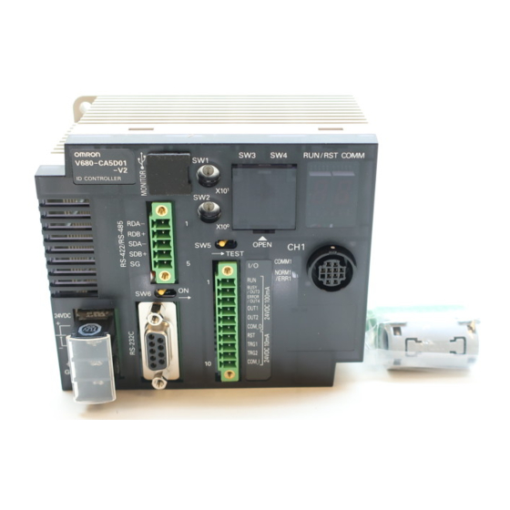
SECTION 1 Product Overview Part Names and Functions Part Names V680-CA5D01-V2 Main Indicators Controller Number Switches Switch Cover USB Port Monitor display Bar Indicator RS-422/RS-485 Port Mode Switch Antenna Port Terminating Resistance Switch Power Supply Terminals Antenna Operation Indicators External I/O Port... - Page 17 If pin 6 on DIP switch SW4 (Lower Trigger Execution Setting) is turned ON, any command already received by Antenna 1 will be executed on the rising edge of the TRG1 Input. If pin 6 is turned OFF, TRG1 is used as user input 1, which can be read using the CONTROLLER CONTROL (CC) com- mand.
- Page 18 RS-422/RS-485 interfaces can be connected. USB Port The USB port is used to connect to a computer via a USB cable. The port is USB 1.1. Communications with host devices using USB connections can be made using only 1:1 protocol, regardless of the setting of pin 9 on DIP switch SW3.
- Page 19 Converts and measures the Antenna output at six levels. Mode ment Mode The level is displayed as either “EE” or 01 to 06. “--” will be displayed if there is no Tag in the Antenna’s com- munications area. Tag Communications Communicates with Tags and displays end codes.
- Page 20 Hexa- decimal Display The error code “15” will be displayed if the operation conditions have not been set and operation is switched to Self-execution Mode. Maintenance Mode (SW5 ON) In Maintenance Mode, the measurement results for each measurement mode is displayed in 2-digit decimal.
- Page 21 SECTION 1 Product Overview Bar Indicator RFID System User’s Manual...
-
Page 22: System Configuration
SECTION 1 Product Overview System Configuration 1:1 Connection One host device is connected via the RS-232C, RS-422, or RS-485 interface. • Using an Antenna Other than the V680-H01 Programmable Controller Personal computer (PLC) RS-232C, RS-422, or RS-485 interface ID Controller... - Page 23 RS-232C, RS-422, or RS-485 interface ID Controller V680-CA5D01-V2 Antennas V680-H01 Pallet or other object The V680-H01 Antenna can be connected only to the V680-CA5D01-V2 ID Controller. It cannot be used with the V680- CA5D02-V2 ID Controller RFID System User’s Manual...
- Page 24 SECTION 1 Product Overview 1:N Connections with RS-232C Connection to Host Device The host device can be connected via RS-232C and then other ID Controllers can be connected via RS-422/RS-485 interfaces. • Using an Antenna Other than the V680-H01 Programmable Controller...
- Page 25 RS-422/RS-485 ID Controller V680-CA5D01-V2 Antennas V680-H01 Pallet or other object Pallet or other object The V680-H01 Antenna can be connected only to the V680-CA5D01-V2 ID Controller. It cannot be used with the V680- CA5D02-V2 ID Controller RFID System User’s Manual...
- Page 26 SECTION 1 Product Overview 1:N Connections with RS-422/RS-485 Connection to Host Device The host device and other ID Controllers can all be connected via RS-422 or RS-485 interfaces. • Using an Antenna Other than the V680-H01 Programmable Controller Personal computer...
- Page 27 RS-422/RS-485 ID Controller V680-CA5D01-V2 Antennas V680-H01 Pallet or other object Pallet or other object The V680-H01 Antenna can be connected only to the V680-CA5D01-V2 ID Controller. It cannot be used with the V680- CA5D02-V2 ID Controller RFID System User’s Manual...
-
Page 28: Application Flowchart
28 Connect the system. p. 30 Set the ID Controller's communications conditions. p. 58 Perform a communications test between the ID Controller and host device. p. 77 Perform a communications test between the Tags and Antennas. p. 78. Check the ambient environment. - Page 29 SECTION 1 Product Overview MEMO RFID System User’s Manual...
-
Page 30: Section 2 Installation, Connections, And Wiring
SECTION 2 Installation, Connections, and Wiring Installation Connection and Wiring RFID System User’s Manual... -
Page 31: Installation
• Locations more than 2,000 m above sea level Mounting in a Panel The ID Controller can be used at an ambient temperature range of − 10 to 55 ° C. Be sure to observe the following precautions. • Make sure that the ID Controller is provided with sufficient ventilation space. - Page 32 Attaching the End Plates To mount an End Plate easily, first hook the bottom of the End Plate and then hook the top on the DIN Track, pull the End Plate downwards and tighten the screw. Recommended tightening torque: 1.2 N·m.
-
Page 33: Connection And Wiring
Installation, Connections, and Wiring Connection and Wiring Power Supply and Ground Wires The power supply and ground terminals use M3 self-rising screws. The following type of crimp termi- nals can be connected to these terminals. Recommended tightening torque: 0.5 N·m... - Page 34 Wrap the power supply lines and ground line together around the ferrite core. Loop them around the ferrite core once so that the ferrite core does not move. The ferrite core should be within 10 cm of the ID Controller.
- Page 35 Precautions for Error Signal Output • The maximum switching capacity for the output is 100 mA at 24 VDC ( − 15% to +10%). Do not use voltages or loads that exceed the switching capacity. Doing so may cause malfunctions.
- Page 36 Lock screws Removing the Connector Completely loosen the two lock screws, hold the protruding part of the connector, and pull straight out. If the connector is difficult to remove, press on the ID Controller while pulling on the connector. Do not connect cables to the connector after attaching the connector to the ID Controller.
- Page 37 XW2Z-@@@S-V OMRON Shield Note 1. The interface cable will have a male connector on the ID Controller and a female connector on the IBM PC/AT or com- patible. 2. Ground the shield at the host device to prevent operation errors.
- Page 38 The ID Controller can be connected to the host device through an OMRON ITNC-SGB01 Serial Gate Box to enable Ethernet TCP/IP communications. An ID Controller connected through a Serial Gate Box can be communicated with in exactly the same way as when the ID Controller is connected through the serial interface.
- Page 39 5 (See note.) Clear to send tape Note: Short-circuit pins 4 (RS) and 5 (CS) with a jumper. Attach housing A2 of the Hood to the Plug and secure the aluminum-taped portion with the cable clamp. Two, M2.6 lock screws Housing A2...
- Page 40 • When disconnecting the connector, completely loosen the two lock screws. Hold the protruding part of the connector hood by hand and pull the connector straight out. If the connector is difficult to dis- connect, hold the ID Controller with your hand while pulling on the connector.
- Page 41 RDA( − ) − RDB( + ) SDA( − ) SDB( + ) Note: Short-circuit terminals 1 and 3, and 2 and 4. Do not connect anything to the ID Controller signal ground. RDA(−) RDB(+) SDA(−) SDB(+) SG Transmission Reception terminating...
- Page 42 SDB(+) SDB(+) Note: Short-circuit terminals 1 and 3, and 2 and 4 to use RS-485 communication. Refer to Connections to Host Device for information on RS-232C connections between the host device and ID Control- lers. p. 34 If the first communications received by an ID Controller are via the RS-232C interface, reception of RS-422/RS-485 communications will be prohibited.
- Page 43 Refer to RS-422 Connections for information on RS-422 connections between the host device and ID Controllers. p. 38 If the first communications received by an ID Controller are via the RS-232C interface, reception of RS-422/RS-485 communications will be prohibited. If the first communications are received via RS-422/RS-485, reception of RS-232C communications will be prohibited.
- Page 44 Lock screws Removing the Connector Completely loosen the two lock screws, hold the protruding part of the connector, and pull straight out. If the connector is difficult to remove, press on the ID Controller while pulling on the connector. Do not connect cables to the connector after attaching the connector to the ID Controller.
- Page 45 Series B end Series A end A cap is attached to the connectors at shipment. Leave this cap on if USB is not being used to prevent dust or foreign matter from entering the connectors and to prevent static electricity.
- Page 46 Install the ferrite core listed above to the cable. 10 cm max. Attach the ferrite core to the Mini USB Series B end. Close the ferrite core until it snaps shut. The ferrite core should be 10 cm or less from the connector.
- Page 47 For details, ask your OMRON representative for information on the USB driver. Installing the USB Driver on the Computers The USB Driver can be used on Windows 2000 or XP. Install the driver on the host device following the procedure corresponding to the operating system being used.
- Page 48 SECTION 2 Installation, Connections, and Wiring Select Search for a suitable driver for my device (recommended) and click the Next Button. Select Specify a location and click the Next Button. Click the Browse Button and select the folder where the downloaded V680-CA5D_100.inf is to be saved.
- Page 49 SECTION 2 Installation, Connections, and Wiring Click the Next Button. The following dialog box will be displayed when the software installation has been completed. Click the Finish Button. RFID System User’s Manual...
- Page 50 Select Ports (COM & LPT) and check that OMRON RFID USB COM is displayed. If the driver is correctly installed the property window for the V680-CA5D@@-V2 will be as follows: Communications with the ID Controller can be performed with the COM number displayed in parentheses after OMRON RFID USB COM.
- Page 51 42 Wait for the following dialog box to be displayed. When the following dialog box is displayed, select Install from a list or specific location (Advanced) and click the Next Button. Click the Browse Button and select the folder in which the downloaded V680-CA5D_100.inf file is to be saved.
- Page 52 SECTION 2 Installation, Connections, and Wiring Click the Continue Button. When the following dialog is displayed, installation is completed. Click the Finish Button. RFID System User’s Manual...
- Page 53 Select Ports (COM & LPT) and check that OMRON RFID USB COM is displayed. If the driver is correctly installed the property window for the V680-CA5D@@-V2 will be as follows: Communications with the ID Controller can be performed with the COM number displayed in parentheses after OMRON RFID USB COM.
- Page 54 SECTION 2 Installation, Connections, and Wiring Windows Vista Turn ON the power to the personal computer and start Windows Vista. Connect the ID Controller to the computer via USB. For details on connection methods, refer to USB Port. p. 42 Wait for the following window to be displayed.
- Page 55 SECTION 2 Installation, Connections, and Wiring When the following window is displayed, select I don’t have the disc. Show me other options. But- ton. When the following window is displayed, select Browse my computer for driver software (advanced) Button. RFID System...
- Page 56 SECTION 2 Installation, Connections, and Wiring Click the Browse Button, and select the folder in which the downloaded file V680-CA5D_200.inf is saved. Then click the Next Button. When the following window is displayed, select Install this driver software anyway Button.
- Page 57 Select Ports (COM & LPT), and check that OMRON RFID USB COM is displayed. If the driver is correctly installed, the property window for the V680-CA5D will be displayed as follows: Communications with the ID Controller can be performed with the COM number displayed in parentheses after OMRON RFID USB COM.
- Page 58 Press the connector in vertically until it locks. Ring Be sure to hold onto the base of the connector. The connector will not lock if Base of connector the ring is held. To remove the connector, hold onto the ring and pull the connector straight out.
- Page 59 SECTION 2 Installation, Connections, and Wiring MEMO RFID System User’s Manual...
-
Page 60: Section 3 Preparations For Communications
SECTION 3 Preparations for Communications Switch Settings Trial Operation RFID System User’s Manual... -
Page 61: Switch Settings
SECTION 3 Preparations for Communications Switch Settings Opening the Cover Open the cover by inserting a small screwdriver into the groove on the cover. Controller Number Switches (SW1, SW2) DIP Switch (SW3) DIP Switch (SW4) Mode Switch (SW5) Terminating Resistance... - Page 62 Preparations for Communications Default Settings Default Name Description Reference setting Controller number upper digit (0 to 9) Controller No. 00 p. 60 Controller number lower digit (0 to 9) SW3, pin 1 SW enable switch DIP Switches enabled SW3, pin 2 Reserved by system.
- Page 63 Controller numbers are not set correctly. SW1 and SW2 are enabled only when the DIP switch is enabled (i.e., when pin 1 on SW3 is OFF). If the internal set- tings are enabled (i.e., if pin 1 on SW3 is ON), the values specified by the PARAMETER SET (SP) command will be enabled.
- Page 64 DIP switch enabled Internal settings enabled Note: SW1, SW2, SW3 (pins 3 to 9), and SW4 (pins 5 to 7) are enabled only when the DIP switches are enabled. When the internal settings are enabled, the values specified by the TR and SP commands are valid.
- Page 65 SW4, Pin 6 (Lower Trigger Execution) SW4, pin 6 Description None Enabled (on rising edge) Note: This setting is valid only when pin 10 on DIP switch SW3 (command system) is ON. SW4, Pin 7 (Write Protection Function) SW4, pin 7 Description Enabled...
- Page 66 Terminating Resistance If two or more ID Controller are connected to one host device, be sure to turn ON the terminating resis- tance of only the Controllers or host devices at each end of the serial connection and turn OFF the ter- minating resistance of any other device.
- Page 67 There are two Run Modes: Command Execution Mode and Self-execution Mode. The Run Mode at startup (when the power is turned ON) can be selected using pin 9 on SW4. The mode can also be changed by executing an OPERATION MODE CHANGE command (MO) from the host device.
- Page 68 4) Output to OUT4. The output time can be set. 5) Return the response to the host computer. Note: There are 2 external outputs (OUT1 and OUT2) if the I/O arrangement is set to the same I/O arrangement as the V600(V680-CA5D@@-V2).
- Page 69 If a write command was being executed, part of the contents of the Tag may have been overwritten. To switch to another mode, change the Test Mode on pins 1 to 3 on DIP switch SW4 then turn ON the mode switch (SW5).
- Page 70 The distance level will be displayed on the bar indicator and monitor display. The level at which normal reading was possible will be displayed between 01 and 06. If there is no Tag in the Antenna’s commu- nications area, “--” will be displayed. The measurement result is also output from the USB port.
- Page 71 The Speed Level Measurement Mode simulates writing data. Actually data is not written to the Tag. The speed level is measured for the number of test bytes set in advance using the PARAMETER SET (SP) command. Refer to PARAMETER SET (SP) for details.
- Page 72 Noise Level Measurement Mode enables checking spatial noise, noise sources, and the effectiveness of noise countermeasures without connecting to a host device. This mode measures the noise level in the surrounding environment and displays the result on the monitor display. A noise level between 00 and 99 can be output from the USB port as the result.
- Page 73 Communications Success Rate Measurement Mode can be used to check the percentage of commu- nications that are successful without connecting to a host device. This mode displays the rate of suc- cessful communications without retries between Antennas and Tags on the monitor display.
- Page 74 Host Communications Monitor Mode (Protocol Analyzer) Commands sent by serial communications (RS-232C, RS-422, or RS-485) from the host device and execution result responses can be output to the monitor port (USB) to enable application as a host communications line protocol analyzer.
- Page 75 The measurement result is also output from the USB port to enable checking on a monitor device, e.g., when the ID Controller is installed in a panel and the monitor dis- play is not visible.
- Page 76 SECTION 3 Preparations for Communications Output from the USB Port The end code and the Antenna channel are output from the USB port. TL 00 1 0 * [CR] Resend Flag (Always "0".) Antenna channel ("1": channel 1, "2": channel 2) End code p.
- Page 77 Host Communications Check Mode can be used to check if data sent from the ID Controller is reaching the external device. In this mode, a response is sent to the host device from the ID Controller, making it easier to identify communications setting or wiring errors that cause faults in connections between ID Controllers and host devices.
- Page 78 · Pin 1 on DIP Switch SW3 Turned OFF (DIP Switch Settings Enabled) The communications settings from pins 3 to 8 of DIP switch SW3 are output as the response. · Pin 1 on DIP Switch SW3 Turned ON (Internal Settings Enabled) The communications settings made with the COMMUNICATIONS SET (TR) command are output as the response.
-
Page 79: Trial Operation
• Check that the supply voltage to the I/O terminals is correct. Turn ON power. • Check that the RUN indicator on the Controller and the POWER indi- cator on the Antenna are lit. Check operation of •... - Page 80 Preparations for Communications Communications Test with Host Device The TEST command is used to perform a communications test of the communications between the Controller and host device. This test enables the cable connections and processing operation of com- munications to be checked before the trial operation of the whole system.
- Page 81 The Controller will read the Tag data once the Tag enters the Antenna's communications area. An error code will be displayed on the monitor display if communications are not successful. If the end code “00” is not displayed on the monitor display, check List of End Codes and correct the error. p. 171 RFID System User’s Manual...
-
Page 82: Section 4 Functions
SECTION 4 Functions Trigger Input Write Protection Tag Service Life Check Tag Memory Check Tag Memory Error Correction Write Command Memory Noise Monitor Function RFID System User’s Manual... -
Page 83: Trigger Input
Response processed If auto commands are used, the ID Controller will wait from the rising edge of the Trigger input for a Tag to enter the communications area. This means that read/write processing will not start after a com- mand is received until the rising edge of the trigger input, even if a Tag approaches. -
Page 84: Write Protection
Write Protection Write protection can be set to protect important data stored in the memory of an ID Tag, such as product num- bers and models from being mistakenly overwritten. After important data has been written to memory, it can be write-protected using the following method. - Page 85 ) of the ID Tag, the write protection setting area can be used for user memory. When the write protection setting area of the ID Tag is used for user memory, be sure to disable the write protection setting of the ID Controller.
- Page 86 Write- 0001 protected 0002 0003 03E7 End Address Is Higher than the Last ID Tag Address The memory area between the start address and the last ID Tag address will be write-protected. 0000 Address Upper digits Lower digits 0000 (Hex)
- Page 87 Disabling Write Protection for all OMRON-made RFID systems: To disable write protection in order to, for example, use the entire memory area of the ID Tag as user memory, use either of the following methods to set all of the ID Controllers.
- Page 88 The ID Controller automatically switches between the V600 EEPROM write protection method and the V600 S-RAM write protection method according to the ID Tag being used, so the user does not need to make this setting. The V600 EEPROM write protection method and the V600 S-RAM write protection method can be used only on ID Con- trollers that are version 2.1 or newer.
- Page 89 03E7 is write-protected. The V600 EEPROM write protection method and the V600 S-RAM write protection method can be used only on ID Con- trollers that are version 2.1 or newer. For details on Checking the Version, refer to page 17.
- Page 90 The V600 EEPROM write protection method and the V600 S-RAM write protection method can be used only on ID Con- trollers that are version 2.1 or newer. For details on Checking the Version, refer to page 17.
- Page 91 Write- 0021 protected area 0004 0005 7FFF End Address Higher than Last ID Tag Address The memory area between the start address and the last ID Tag address will be write-protected. Address Address Upper digits Lower digits 0000 0002 0003...
- Page 92 SECTION 4 Functions Start Address Higher Than End Address The memory area between the start address and the last ID Tag address, as well as the area between 0006H and the end address will be write-protected. Address Upper digits Lower digits...
- Page 93 Setting Write Protection for V680 Models The same method is used as that for setting ID Tags when using V680 commands. Refer to step 2 (Set the write protection function of the ID Tag) of Setting Write Protection when Using V680 Commands.
-
Page 94: Tag Service Life Check
The overwrite count control area consists of 3 bytes from the specified start address. The decrement value from the overwrite count is written in this area, and if this value is 0 (00 hex), an end code 76 will be given as a warning. Therefore, to enable control of the number of overwrites, the maximum number of overwrites must be written to the overwrite count control area beforehand. - Page 95 If “MDSTS1001000” is executed now, “MD7610” (overwrite count exceeded) will be returned. 0010 0011 0010 0012 0011 0012 Do not execute the MDS command and MDL command for the same Tag. Doing so will prevent managing the service life. RFID System User’s Manual...
-
Page 96: Tag Memory Check
Functions Tag Memory Check The DATA CHECK command (MD C/K) performs a memory check. A CRC (Cyclic Redundancy Check) code calculation, write, and comparison are made using the check block unit specified by the user. The CRC code is calculated from the generated polynomial expression x + 1. -
Page 97: Tag Memory Error Correction
Error correct code (leftmost) Error correct code (mid) Error correct code (rightmost) For details on the command format, refer to READ TAG MEMORY ERROR CORRECTION (QR) and WRITE TAG MEMORY ERROR CORRECTION (QW). p. 136, p. 138 Example of Tag Memory Error Correction... -
Page 98: Write Command Memory
Functions Write Command Memory A write command executed by the V680-CA5D01/02 ID Controller is stored in memory until the next write command is executed or until the power is reset. Write commands include WRITE, EXPANSION WRITE, AUTO WRITE, and POLLING AUTO WRITE. The write command stored in memory can be executed using the WRITE REPEAT (RP) command. -
Page 99: Noise Monitor Function
The noise monitor function cannot be used when the V680-H01 Antenna is connected. To use the noise monitor function it must be enabled using the PARAMETER SET (SP) command. p. 147 Response Examples ●... -
Page 100: Section 5 Communications
SECTION 5 Communications Tag Operation and Command Status V600-V680 Command Correspondence V680 Commands V600 Commands RFID System User’s Manual... -
Page 101: Tag Operation And Command Status
Communications Control Protocol The communications control procedure conforms to OMRON's SYSWAY protocol. (1) The first right to send is held by the host device, and it is transferred to the ID Controller after a command is sent. (2) When a response is returned from the ID Controller, the right to send is transferred back to the host device. - Page 102 Antenna. When a response is being returned from the ID Controller to the host device, the ID Controller cannot correctly receive commands from the host device. Do not send commands while a response is being returned.
- Page 103 SECTION 5 Communications Data Code Designation Data to be read or written is specified in the command to be handled as either ASCII (JIS8 code) char- acter data or as hexadecimal data. ASCII (JIS8 Code) Designation • Each data character is allocated 1 byte (1 address) of Tag mem- •...
-
Page 104: V600-V680 Command Correspondence
V680 command can be used to take advantage of newly implemented functions. The command series that is being used is specified on pin 10 of DIP switch SW3. V680 and V600 commands corresponds as shown in the following tables. - Page 105 SECTION 5 Communications Controller Control Commands V680 Commands V600 Commands Com- Com- Name mand Name mand code code COMMUNICATIONS SET COMMUNICATIONS SET PARAMETER SET PARAMETER SET OPERATION MODE CHANGE OPERATION CONDITION SET RESPONSE RESEND CONTROLLER CONTROL CONTROLLER CONTROL READ ERROR INFORMATION...
-
Page 106: V680 Commands
Single auto When the ID Controller receives a command, it waits to detect a Tag in the Antenna's com- munication area. When the ID Controller detects a Tag, it communicates with the Tag and then returns a response. - Page 107 When the ID Controller has completed communi- cating with the Tag, it sends a response to the host device and then waits for another command. If there is no Tag in the communications error when the ID Controller receives the command from the host device, the ID Controller returns a Tag missing error (error code: 72).
- Page 108 Tag enters the antenna's communications area. Antenna Single Auto Designation (SA) With a single auto designation, the ID Controller communicates with the Tag, returns a response to the host device, and then enters command standby status. SA Mode command Host device to Controller - Processing completed.
- Page 109 Communications Polling Auto Designation (PA) A polling auto designation causes the ID Controller to return a response indicating reception of a poll- ing command and then perform the operation for a single auto designation (SA). The ID Controller does not return a response until it receives the POLLING QUERY command (PC) (see note 1). The POLLING QUERY command (PC) (see note 2) is also used to cancel processing.
- Page 110 Communications External Trigger Communications Designations (SI, RI, and PI) The ID Controller communicates with a Tag on the rising edge of the TRG external input signal. These designations can be used to accurately perform communications even on high-speed lines because communications can be directly controlled with the output of a sensor that detects when Tags are in the Antenna's communications area.
- Page 111 (SI). The ID Control- ler does not return a response until it receives the POLLING QUERY command (PC) (see note 1). The POLLING QUERY command (PC) (see note 2) is also used to cancel processing.
- Page 112 Tag that enters the Antenna's communications area. If two or more Tags enter the Antenna's communications area at the same time, an error will result. If a Tag whose access is prohibited leaves the Antenna's communications area, it becomes once again capable of communicating.
- Page 113 Note: Multi-access communications designations (MT/MR) cannot be used for communicating with V680-D1KP@@ Tags. Selective Communications Designation (SL) The ID Controller communicates only with Tags having the UID that is designated by the command from among all of the Tags in the Antenna's communications area. The ID Controller communicates only...
- Page 114 Name Description Controller No. When using 1:N protocol, the Controller number (00 to 31) is added after the @ mark and the 0. (In decimal) Command code A code that specifies the command to be executed. A unique identifier used to identify Tags.
- Page 115 FCS calculation range Name Description Command code For all commands other than an RP or PC command, the data that is in the transmitted command frame is added and returned. End code Indicates the execution result for the command. Refer to List of End Codes for information on end codes.
- Page 116 AUTO COPY Waits for Tags to approach and then reads data from the memory of a p. 131 Tag using one Antenna and writes it to the memory of the Tag in the other Antenna's communications area. LARGE READ Reads up to 8 KB of data from a Tag.
- Page 117 SECTION 5 Communications Controller Control Commands The controller control commands are used to set communication parameters or when resending the response. Command Name Description Page code UID ADDITION SET Sets whether or not UID should be added to the read command (RD) p.
- Page 118 SECTION 5 Communications FCS Calculation Example Reading 5 Bytes Started from Address 0010 Data Command Controller No. Terminator code FCS calculation range ASCII (hex) Binary Original data 0100 0000 0011 0000 0011 0000 0011 0010 Converted to Converted to 0101...
- Page 119 A unique identifier used to identify Tags. Added only for the selective communications designation (SL). Read area start address Specifies the start address of the area in the Tag from which data is to be read from in 4-digit hexadecimal. Setting range: 0000 to FFFF No.
- Page 120 A unique identifier used to identify Tags. Added only for the selective communications designation (SL). Read area start address Specifies the start address of the area in the Tag from which data is to be read from in 4-digit hexadecimal. Setting range: 0000 to FFFF No.
- Page 121 A unique identifier used to identify Tags. Added only for the selective communications designation (SL). Write area start address Specifies the start address of the area in the Tag to which data is to be written in 4-digit hexadec- imal. Setting range: 0000...
- Page 122 A unique identifier used to identify Tags. Added only for the selective communications designation (SL). Write area start address Specifies the start address of the area in the Tag to which data is to be written in 4-digit hexadec- imal. Setting range: 0000...
- Page 123 The DATA FILL command writes the designated data for the specified number of bytes beginning from the specified start address. This command will write data even to areas of the Tag for which write protection has been set. Confirm that there is no important data in the area being written before executing this command.
- Page 124 SECTION 5 Communications Example In this example, 0101H is written to Tag memory for 0006H bytes starting from address 0030H using Antenna 1. The communications designation is “ST”. Command Antenna designation Communi- Data Command cations desig- Terminator Designated data Write area start address No.
- Page 125 A unique identifier used to identify Tags. Added only for the selective communications designation (SL). Write area start address Specifies the start address of the area in the Tag to which data is to be written in 4-digit hexadec- imal. Setting range: 0000 to FFFF No.
- Page 126 OVERWRITE COUNT CONTROL (MD S/L) The OVERWRITE COUNT CONTROL command is used to manage overwrite counts for EEPROM Tags. The specified overwrite count control area data is updated to enable determining when the EEPROM's write life has expired. 1:1 Protocol...
- Page 127 Setting range: 00 to FF : Performs overwrite count check only.) Refer to Tag Service Life Check for details. p. 91 Note: The write life for EEPROM Tags is 300,000 writes at 40 ° C. Response Antenna Resend flag desig- Command Controller No.
- Page 128 SECTION 5 Communications DATA CHECK (MD C/K) The DATA CHECK command is used to write or verify the CRC code in the specified check block. The CRC code is generated using the following polynomial X + 1. 1:1 Protocol Command...
- Page 129 Setting range: 00 , 03 to FF (Specify 00H for 256 bytes.) Specify the number of bytes in the check code calculation area plus two for the number of check block bytes. Refer to Tag Memory Error Correction for details. p. 94...
- Page 130 Write command information is cleared at the following time. • When the ID Controller's power supply is reset. If a WRITE REPEAT command is executed after write command information has been cleared, a command input error will occur. 1:N Protocol...
- Page 131 Note: Not added when an error is generated. The ID code is written in the memory of the Tag and may be affected by data retention characteristics at high tempera- tures. Take suitable precautions when using the READ ID command for Tags operating at high temperatures.
- Page 132 Only in the case of the selective communications designation (SL), the UID of the Tag that is being written to is added to the data. Read area start address Specifies the start address of the area in the Tag from which data is to be read from in 4-digit hexadecimal. Setting range: 0000 to FFFF No.
- Page 133 Only in the case of the selective communications designation (SL), the UID of the Tag that is being written to is added to the data. Read area start address Specifies the start address of the area in the Tag from which data is to be read from in 4-digit hexadecimal. Setting range: 0000 to FFFF No.
- Page 134 When the ID Controller receives an AUTO COPY command, it waits for Tags to approach and then reads data from the memory of a Tag using one Antenna and writes it to the memory of the Tag in the other Antenna's communications area. This command cannot be used with the V680-CA5D01-V2.
- Page 135 Only in the case of the selective communications designation (SL), the UID of the Tag that is being written to is added to the data. Read area start address Specifies the start address of the area in the Tag from which data is to be read from in 4-digit hexadecimal. Setting range: 0000 to FFFF No.
- Page 136 Communications LARGE READ (ER) The LARGE READ command reads up to 8 KB of data from a Tag. If there is no Tag, the ID Controller returns an error response with an error code of 72 (Tag missing error). 1:1 Protocol...
- Page 137 Read data The data read from the Tag. The number of characters will be the same as the specified number of bytes to read for ASCII data and twice that number for hexadecimal data. RFID System...
- Page 138 In the case of multi-access communications designations (MT/MR), the UID of the Tag that is being written to is added to the data. Read area start address Specifies the start address of the area in the Tag from which data is to be read from in 4-digit hexadecimal. Setting range: 0000 to FFFF No.
- Page 139 A unique identifier used to identify Tags. Added only for the selective communications designation (SL). Read area start address Specifies the start address of the area in the Tag from which data is to be read from in 4-digit hexadecimal. Setting range: 0000 to FFFA No.
- Page 140 A unique identifier used to identify Tags. Added only for the selective communications designation (SL). Read area start address Specifies the start address of the area in the Tag from which data is to be read from in 4-digit hexadecimal. Setting range: 0000 to FFFF No.
- Page 141 A unique identifier used to identify Tags. Added only for the selective communications designation (SL). Read area start address Specifies the start address of the area in the Tag from which data is to be read from in 4-digit hexadecimal. Setting range: 0000 to FFFA No.
- Page 142 A unique identifier used to identify Tags. Added only for the selective communications designation (SL). Read area start address Specifies the start address of the area in the Tag from which data is to be read from in 4-digit hexadecimal. Setting range: 0000 to FFFA No.
- Page 143 “2”: Antenna 2 Response When a Processing Results Query Is Executed after Tag Communications The ID Controller returns a response according to the specifications of the polling command that was executed. Response When a Processing Results Query Is Executed before Tag Communications...
- Page 144 “2”: Antenna 2 Response When a Processing Results Query Is Executed after Tag Communications The ID Controller returns a response according to the specifications of the polling command that was executed. Response When a Processing Results Query Is Executed before Tag Communications...
- Page 145 SECTION 5 Communications COMMAND PROCESSING TERMINATE (AA) The COMMAND PROCESSING TERMINATE command cancels any command except for polling commands and returns the ID Control to command standby status. 1:1 Protocol Command Antenna designation Process Command desig- Terminator code nation Response...
- Page 146 The ABORT command can be used to reset the ID Controller to command standby status during com- munications with the host device or a Tag if any sort of trouble occurs, e.g., if the ID Controller does not return a response. The ID Controller will return to command standby status after it is reset. The ID Controller does not return a response to the ABORT command.
- Page 147 SECTION 5 Communications CONTROLLER CONTROL Commands UID ADDITION SET (US) Sets whether or not UID should be added to the read command (RD) response or read tag memory error correction (QR) response. 1:1 Protocol Command Process Command desig- Fixed code...
- Page 148 The COMMUNICATIONS SET command is used to set serial communications parameters. To use the ID Controller with the new parameters, either restart the ID Controller or execute the ABORT command (XZ). This command is valid only when internal settings are enabled (i.e., when pin 1 on SW3 is ON). 1:1 Protocol Command...
- Page 149 Specify the type of parity. “0”: None “1”: Odd parity “2”: Even parity Default setting: Even parity Stop bit length Specify the number of stop bits. “1”: 1 bit “2”: 2 bits Default setting: 2 bits Response Resend flag Fixed Command Controller No.
- Page 150 The PARAMETER SET command is used to set conditions for communicating with Tags. The various parameters are set in the ID Controller. The ID Controller does not need to be reset when internal settings are changed. The new settings are effective immedi- ately.
- Page 151 “01”: Write protection ON (default value) Note 1: Parameters 1, 2, 9, and H are valid only when internal settings are enabled (i.e., when pin 1 on SW3 is ON). Note 2: The data number of the parameter data is the number specified for the lower digit of the process code.
- Page 152 “01”: Write protection ON (default value) Note 1: Parameters 1, 2, 9, and H are valid only when internal settings are enabled (i.e., when pin 1 on SW3 is ON). Note 2: The data number of the parameter data is the number specified for the lower digit of the process code.
- Page 153 Communications Response Resend flag Command Fixed Terminator Controller No. End code value code Parameter data × × × × × × × × 1 to 4 Parameter data Attached only when parameter data is being obtained. RFID System User’s Manual...
- Page 154 If the OPERATION MODE CHANGE command is executed in Host Communications Monitor Mode with the process designation set to “S,” an execution status error (end code 15) will occur. To change from Host Communications Monitor Mode to Self Execution Mode, first change to Command Execution Mode.
- Page 155 SECTION 5 Communications Response Resend flag Fixed Command value Terminator Controller No. End code code × × × × RFID System User’s Manual...
- Page 156 “C2”: Sets an execution command for channel 2. Note: “C2” will result in an error (15) if specified for a One-channel Controller (V680-CA5D01-V2). Also, if execution commands are not set for both channels 1 and 2 for a Two-channel Controller (V680-CA5D02-V2), the output conditions cannot be set.
- Page 157 “S3”: OUT3 output condition setting “S4”: OUT4 output condition setting Note: “S3” or “S4” will result in an error (15) in Two Output Mode. Also, if output conditions are not set for OUT1 through OUT3, the execution command output destination cannot be set.
- Page 158 × × × × × Note: There are the following three patterns for comparison conditions A and B depending on the con- ditions. • When Data Criteria Are Used for Conditions A and B Comparison Number of data Comparison parameters...
- Page 159 C 1 . . . ; C 2 . . . ; S 1 . . . ; S 2 . . . ; S 3 . . . ; S 4 . . . ; U 1 . . .
- Page 160 For the V680-CA5D01-V2, set an execution command only for channel 1. Set the conditions. OUT1 Output Condition (Turn ON output OUT1 for 100 ms if the 2 bytes of data from 0000 bytes of the data read from channel 1 is greater than 1234.) Command: SE00S101>=00000212340100*[CR]...
- Page 161 SECTION 5 Communications Read the operation conditions. Reading Operation Conditions Command: SE10*[CR] Response: SE00C1RDRAH100100010; C2XX; S101>=00000212340100; S201ER000000000100 ; S3XX; S4XX; U101AL; U2XX*[CR] CH1 command OUT1 output condition OUT2 output condition CH1 output OUT3 output condition setting CH2 output CH2 command...
- Page 162 SECTION 5 Communications RESPONSE RESEND (RR) The RESPONSE RESEND command causes the ID Controller to resend the most recent response. The RESPONSE RESEND command cannot be used to reset a response for the LARGE READ (ER) command. 1:1 Protocol Command Command...
- Page 163 SECTION 5 Communications CONTROLLER CONTROL (CC) The CONTROLLER CONTROL command is used to manipulate or read I/O. 1:1 Protocol Command OUT4 OUT2 control control OUT1 Command OUT3 control Terminator code control × × × × OUT1/OUT2 controls 0: Read 1: Turn ON...
- Page 164 1: ON OUT3/4 Output status The output status of OUT3 and OUT4 after execution. • Output setting: Two Output Mode (BUSY, ERROR, OUT1, and OUT2) X: Fixed • Output setting: Four Output Mode (OUT1, OUT2, OUT3, and OUT4) 0: OFF...
- Page 165 A space will be output for when the error is not a communications error. Error command Example This example shows the response for when a format error occurred for a command and then a Tag communications error occurred for a READ command. Both errors occurred for Antenna 1. Response...
- Page 166 × New error log information Up to 30 records of error log information will be returned. Error log information is returned in chronological order with the newest records first. Each record is five characters long. RD 1 70 ; Generated end code Head No.
- Page 167 “1”: Antenna 1 “2”: Antenna 2 The error log information will not be cleared even if clearing the Controller history information is specified (process des- ignation 1). Use the READ ERROR INFORMATION (CF) command to clear the error log information.
- Page 168 “1”: Antenna 1 “2”: Antenna 2 The error log information will not be cleared even if clearing the Controller history information is specified (process des- ignation 1). Use the READ ERROR INFORMATION (CF) command to clear the error log information.
- Page 169 The TEST command is used to test communications between the host device and ID Controller. The TEST command is used to send a text message from the host device to the ID Controller. The ID Con- troller returns the same text message unaltered.
- Page 170 SECTION 5 Communications VERSION READ (VS) The VERSION READ command is used to read the Controller's software model, software version, and software creation date. 1:1 Protocol Command Command Terminator code Response Resend flag Command Fixed End code value Terminator code...
- Page 171 SECTION 5 Communications Evaluation Command NOISE DETECTION (NS) The NOISE DETECTION command is used to check the noise level when the command is received. This Command cannot be used when the V680-H01 Antenna is connected. 1:1 Protocol Command Antenna designation...
- Page 172 × × × × × Average noise level Gives the average noise level that was measured. “00” to “99” Maximum noise level Gives the maximum noise level that was measured. “00” to “99” Minimum noise level Gives the minimum noise level that was measured.
- Page 173 SECTION 5 Communications Other Command Codes UNDEFINED COMMAND RESPONSE (IC) If the ID Controller receives a command code that it cannot interpret, it will return a response for the undefined command. 1:1 Protocol Response Command Fixed Resend code End code...
- Page 174 Normal end Command processing terminated. Polling command query (after communications with Tag were completed normally) Polling command cancelled. Normal end (no error) for DATA CHECK command or OVERWRITE COUNT CONTROL command Polling command received. Polling command query (no results information)
-
Page 175: V600 Commands
(with Tag) along the production line. Auto Read/Write Functions Auto Command Processing The ID Controller does not return a response for AUTO commands until a Tag is within range. The communications path with the host device is busy during this time. (Host device) - Page 176 SECTION 5 Communications Using AUTO READ/AUTO WRITE Commands Normally, read/write commands are used when a Tag is in the communications area. The AUTO READ and AUTO WRITE commands are used for moving Tags. ● READ or WRITE Command ● AUTO READ or AUTO WRITE Command •...
- Page 177 With a POLLING AUTO command, however, the ID Controller returns a response only when a request is received from the host device. Therefore, the communications path does not continue to remain in busy status and the host device can send a command to the other Antenna connected to the same ID Controller.
- Page 178 Name Description Controller No. The Controller number (00 to 31) is included only for 1:N protocol. The Controller number must be preceded by the @ mark and is specified as a decimal value. Command code A 2-character code that specifies the command to be executed is added.
- Page 179 Writes data to the memory of the Tag. p. 180 EXPANSION READ Reads up to 2 KB of data from the Tag by dividing the response into frames. p. 182 EXPANSION Writes up to 2 KB of data from the Tag by dividing the command into frames.
- Page 180 Description Page code TEST Checks the communications conditions between the ID Controller and host p. 223 device. The data sent by the host device is returned by the ID Controller without modification. CONTROLLER Controls ID Controller I/O. p. 224 CONTROL READ ERROR Reads the error log.
- Page 181 This section describes the commands that are used to communicate with Tags. READ (RD) The READ command reads data from a Tag. If there is no Tag in the communications area, the ID Con- troller will return an error response with an error code of 72 (Tag missing error).
- Page 182 Specifies the Antenna with which to communicate. “1”: Antenna 1 “2”: Antenna 2 Read area start address Specifies the start address of the area in the Tag from which data is to be read from in 4-digit hexadecimal. Setting range: 0000 to FFFF No.
- Page 183 Communications WRITE (WT) The WRITE command writes data to a Tag. If there is no Tag in the communications area, the ID Con- troller will return an error response with an error code of 72 (Tag missing error). 1:1 Protocol...
- Page 184 Specifies the Antenna with which to communicate. “1”: Antenna 1 “2”: Antenna 2 Write area start address Specifies the start address of the area in the Tag to which data is to be written in 4-digit hexadecimal. Setting range: 0000 to FFFF Write data Specified the data to be written to the Tag.
- Page 185 Specifies the Antenna with which to communicate. “1”: Antenna 1 “2”: Antenna 2 Read area start address Specifies the start address of the area in the Tag from which data is to be read from in 4-digit hexadecimal. Setting range: 0000 to FFFF No.
- Page 186 (CR). When the ID Controller sends any response frame except for the last one, it will wait for the host device to return a delimiter (CR). When the ID Controller receives the delimiter, it will send the next response frame.
- Page 187 Specifies the Antenna with which to communicate. “1”: Antenna 1 “2”: Antenna 2 Read area start address Specifies the start address of the area in the Tag from which data is to be read from in 4-digit hexadecimal. Setting range: 0000 to FFFF No.
- Page 188 (CR). When the ID Controller sends any response frame except for the last one, it will wait for the host device to return a delimiter (CR). When the ID Controller receives the delim- iter, it will send the next response frame.
- Page 189 EXPANSION WRITE (XW) The EXPANSION WRITE command writes up to 2 KB of data to a Tag by dividing the command into frames. If there is no Tag in the communications area, the ID Controller will return an error response with an error code of 72 (Tag missing error).
- Page 190 Method for Dividing Frames 1. Divide the command into frames with 271 or fewer characters each. 2. Attach the terminator (*CR) to the last frame (frame n) only. Attach the delimiter (CR) to the end of all other frames. 3. Be sure to include the command code, data designation, antenna designation, and start address in the first frame (frame 1).
- Page 191 Specifies the Antenna with which to communicate. “1”: Antenna 1 “2”: Antenna 2 Write area start address Specifies the start address of the area from which data is to be written in 4-digit Setting range: 0000 to FFFF Write data Specified the data to be written to the Tag.
- Page 192 Method for Dividing Frames 1. Divide the command into frames with 271 or fewer characters each. 2. Attach the terminator (* CR) to the last frame (frame n) only. Attach the delimiter (CR) to the end of all other frames.
- Page 193 Communications LARGE READ (ER) The LARGE READ command reads up to 8 KB of data from a Tag. If there is no Tag, the ID Controller returns an error response with an error code of 72 (Tag missing error). 1:1 Protocol...
- Page 194 235 Read data The data read from the Tag. The number of characters will be the same as the specified number of bytes to read for ASCII data and twice that number for hexadecimal data. RFID System User’s Manual...
- Page 195 Specifies the Antenna with which to communicate. “1”: Antenna 1 “2”: Antenna 2 Read area start address Specifies the start address of the area in the Tag from which data is to be read from in 4-digit hexadecimal. Setting range: 0000 to FFFF No.
- Page 196 235 Read data The data read from the Tag. The number of characters will be the same as the specified number of bytes to read for ASCII data and twice that number for hexadecimal data. RFID System User’s Manual...
- Page 197 Specifies the Antenna with which to communicate. “1”: Antenna 1 “2”: Antenna 2 Read area start address Specifies the start address of the area in the Tag from which data is to be read from in 4-digit hexadecimal. Setting range: 0000 to FFFF No.
- Page 198 Specifies the Antenna with which to communicate. “1”: Antenna 1 “2”: Antenna 2 Read area start address Specifies the start address of the area in the Tag from which data is to be read from in 4-digit hexadecimal. Setting range: 0000 to FFFF No.
- Page 199 Specifies the Antenna with which to communicate. “1”: Antenna 1 “2”: Antenna 2 Write area start address Specifies the start address of the area in the Tag to which data is to be written in 4-digit hexadecimal. Setting range: 0000 to FFFF Write data Specified the data to be written to the Tag.
- Page 200 Specifies the Antenna with which to communicate. “1”: Antenna 1 “2”: Antenna 2 Write area start address Specifies the start address of the area in the Tag to which data is to be written in 4-digit hexadecimal. Setting range: 0000 to FFFF Write data Specified the data to be written to the Tag.
- Page 201 Specifies the Antenna with which to communicate. “1”: Antenna 1 “2”: Antenna 2 Write area start address Specifies the start address of the area in the Tag to which data is to be written in 4-digit hexadecimal. Setting range: 0000 to FFFF No.
- Page 202 SECTION 5 Communications Example 1 The following example fills 6 bytes (0006H) of memory starting from address 0030H with 0101H for a Tag in which the same data as the address is written. Command R/W Head channel designation Data Write area start...
- Page 203 Specifies the Antenna with which to communicate. “1”: Antenna 1 “2”: Antenna 2 Write area start address Specifies the start address of the area in the Tag to which data is to be written in 4-digit hexadec- imal. Setting range: 0000 to FFFF No.
- Page 204 Specifies the Antenna with which to communicate. “1”: Antenna 1 “2”: Antenna 2 Write area start address Specifies the start address of the area in the Tag to which data is to be written in 4-digit hexadecimal. Setting range: 0000 to FFFF No.
- Page 205 Specifies the Antenna with which to communicate. “1”: Antenna 1 “2”: Antenna 2 Write area start address Specifies the start address of the area in the Tag to which data is to be written in 4-digit hexadecimal. Setting range: 0000 to FFFF No.
- Page 206 ID Controller will return an error response with an error code of 72 (Tag missing error). If there is no Tag to write to, the ID Controller will return an error response with an error code of 76 (copy error).
- Page 207 “1”: Reads from Antenna 1 and writes to Antenna 2. “2”: Reads from Antenna 2 and writes to Antenna 1. Read area start address Specifies the start address of the area in the Tag from which data is to be read from in 4-digit hexadecimal. Setting range: 0000 to FFFF No.
- Page 208 When the ID Controller receives the AUTO COPY command, it waits for Tags to approach and then reads data from the memory of the Tag using one Antenna and writes it to the memory of the Tag in the other Antenna's communications area. An error response (end code 76: copy error) will be returned if there is no Tag at the copy destination.
- Page 209 “1”: Reads from Antenna 1 and writes to Antenna 2. “2”: Reads from Antenna 2 and writes to Antenna 1. Read area start address Specifies the start address of the area in the Tag from which data is to be read from in 4-digit hexadecimal. Setting range: 0000 to FFFF No.
- Page 210 Specifies the Antenna with which to communicate. “1”: Antenna 1 “2”: Antenna 2 Read area start address Specifies the start address of the area in the Tag from which data is to be read from in 4-digit hexadecimal. Setting range: 0000 to FFFF No.
- Page 211 Indicates the execution result for the command. “00”: Normal end “74”: No Tag has approached when polling auto processing results were requested. “75”: No Tag has approached when polling auto processing was cancelled. “76”: Communications processing was in progress or completed when polling auto processing was cancelled.
- Page 212 Specifies the Antenna with which to communicate. “1”: Antenna 1 “2”: Antenna 2 Read area start address Specifies the start address of the area in the Tag from which data is to be read from in 4-digit hexadecimal. Setting range: 0000 to FFFF No.
- Page 213 Indicates the execution result for the command. “00”: Normal end “74”: No Tag has approached when polling auto processing results were requested. “75”: No Tag has approached when polling auto processing was cancelled. “76”: Communications processing was in progress or completed when polling auto processing was cancelled.
- Page 214 Specifies the Antenna with which to communicate. “1”: Antenna 1 “2”: Antenna 2 Write area start address Specifies the start address of the area in the Tag to which data is to be written in 4-digit hexadecimal. Setting range: 0000 to FFFF Write data Specified the data to be written to the Tag.
- Page 215 Indicates the execution result for the command. “00”: Normal end “74”: No Tag has approached when polling auto processing results were requested. “75”: No Tag has approached when polling auto processing was cancelled. “76”: Communications processing was in progress or completed when polling auto processing was cancelled.
- Page 216 Specifies the Antenna with which to communicate. “1”: Antenna 1 “2”: Antenna 2 Write area start address Specifies the start address of the area in the Tag to which data is to be written in 4-digit hexadecimal. Setting range: 0000 to FFFF Write data Specified the data to be written to the Tag.
- Page 217 Indicates the execution result for the command. “00”: Normal end “74”: No Tag has approached when polling auto processing results were requested. “75”: No Tag has approached when polling auto processing was cancelled. “76”: Communications processing was in progress or completed when polling auto processing was cancelled.
- Page 218 SECTION 5 Communications DATA CHECK (MD C/K) The DATA CHECK command is used to write or verify the CRC code in the specified check block. The CRC code is generated using the following polynomial X + 1. 1:1 Protocol Command...
- Page 219 , 03 to FF (Specify 00H for 256 bytes.) Specify the number of bytes in the check code calculation area plus two for the number of check block bytes. Refer to Tag Memory Error Correction Function for details. p. 94...
- Page 220 OVERWRITE COUNT CONTROL (MD S/L) The OVERWRITE COUNT CONTROL command is used to manage overwrite counts for EEPROM Tags. The specified overwrite count control area data is updated to enable determining when the EEPROM's write life has expired. 1:1 Protocol...
- Page 221 : Performs overwrite count check only) Refer to Tag Service Life Check for details. p. 91 Note: The write life for EEPROM Tags is 300,000 writes at 40 ° C. When set to @@@6 to @@@7H or @@@E to @@@F , an address error (code: 7A (hexadecimal)) will be returned as the end code.
- Page 222 Write command information is cleared at the following time. • When the ID Controller's power supply is reset. If a WRITE REPEAT command is executed after write command information has been cleared, a command input error will occur. RFID System...
- Page 223 Write command information is cleared at the following time. • When the ID Controller's power supply is reset. If a WRITE REPEAT command is executed after write command information has been cleared, a command input error will occur. RFID System...
- Page 224 The COMMAND PROCESSING TERMINATE command cancels any command except for polling commands and returns the ID Control to command standby status. This command can also be used to cancel communications for expansion commands with divided frames before completion of the expan- sion command.
- Page 225 The ABORT command can be used to reset the ID Controller to command standby status during com- munications with the host device or a Tag if any sort of trouble occurs, e.g., if the ID Controller does not return a response. The ID Controller does not return a response to the ABORT command.
- Page 226 The TEST command is used to test communications between the host device and ID Controller. The TEST command is used to send a text message from the host device to the ID Controller. The ID Con- troller returns the same text message unaltered.
- Page 227 End code Indicates the execution result for the command. “00” indicates a normal end. Refer to List of End Codes for information on other end codes. p. 235 Input status The current input status (1st character: TRG1, 2nd character: TRG2)
- Page 228 End code Indicates the execution result for the command. “00” indicates a normal end. Refer to List of End Codes for information on other end codes. p. 235 Input status The current input status (1st character: TRG1, 2nd character: TRG2)
- Page 229 SECTION 5 Communications READ ERROR INFORMATION (CF) The READ ERROR INFORMATION command is used to read the most recent error log information stored in the Controller. 1:1 Protocol Command Process Command Terminator code code × × Process code Specifies the process to execute.
- Page 230 235 New error log information Up to 30 records of error log information will be returned. Error log information is returned in chronological order with the newest records first. Each record is five characters long. RD 1 70 Generated error code Head No.
- Page 231 The COMMUNICATIONS SET command is used to set serial communications parameters. To use the ID Controller with the new parameters, either restart the ID Controller or execute the ABORT command (XZ). This command is valid only when internal settings are enabled (i.e., when pin 1 on SW3 is ON). 1:1 Protocol Command...
- Page 232 Controller No. End code code × × × × End code Indicates the execution result for the command. “00” indicates a normal end. Refer to List of End Codes for information on other end codes. p. 235 RFID System User’s Manual...
- Page 233 The PARAMETER SET command is used to set conditions for communicating with Tags. The various parameters are set in the ID Controller. The ID Controller does not need to be reset when internal settings are changed. The new settings are effective immedi- ately.
- Page 234 “1”: V600 write protection Note 1: Parameters 1, 2, 9, B, and H are valid only when internal settings are enabled (i.e., when pin 1 on SW3 is ON). Note 2: Parameter J is valid only for version 2.1 or newer.
- Page 235 “1”: V600 write protection Note 1: Parameters 1, 2, 9, B, and H are valid only when internal settings are enabled (i.e., when pin 1 on SW3 is ON). Note 2: Parameter J is valid only for version 2.1 or newer.
- Page 236 Refer to List of End Codes for information on other end codes. p. 235 Parameter data Attached only when parameter data is being obtained. Parameter J is valid only for version 2.1 or newer. For details on Checking the Version, refer to page 17. RFID System User’s Manual...
- Page 237 Communications Other Command Codes UNDEFINED COMMAND RESPONSE (IC) If the ID Controller receives a command code that is not in the list of commands, it will return a response for the undefined command to the host device. 1:1 Protocol Response...
- Page 238 Auto command cancelled. (Processing cancelled before a Tag was detected.) Polling command cancelled. (Processing cancelled before a Tag was detected.) Normal end for DATA CHECK command or OVERWRITE COUNT CONTROL command (no error) Auto command cancelled. (Processing cancelled after a Tag was detected.) Polling command cancelled.
- Page 239 SECTION 5 Communications MEMO RFID System User’s Manual...
-
Page 240: Section 6 Troubleshooting
SECTION 6 Troubleshooting Self-diagnostic Function Error Lists Errors and Countermeasures Maintenance and Inspection Troubleshooting RFID System User’s Manual... -
Page 241: Self-Diagnostic Function
Antenna and a Tag, an error code will be displayed on the monitor display (error code display mode). Details of up to 30 errors can be stored in memory and can be read with a command from the host device. - Page 242 CPU error Fatal Antenna power supply error error Internal memory error Emergency External reset input ON stop : Lit yellow : Not lit : Lit green : Lit red USR: Set with a CONTROLLER CONTROL command. RFID System User’s Manual...
-
Page 243: Error Lists
• Tag communications errors are those that occur during communications between the ID Controller, Anten- nas, and Tags. • The error details are all logged in the ID Controller memory and the error codes are displayed on the monitor display. Error data can be read using the READ ERROR INFORMATION (CF) command. - Page 244 SECTION 6 Troubleshooting 2. An Amplifier error (error code 7C) will occur if an Amplifier is not connected to the ID Controller when using an Antenna with a Separate Amplifier. A Tag missing error (error code 72) will occur if the Antenna is not connected to the Amplifier.
- Page 245 Antennas, and Tags. • The error details are all logged in the ID Controller memory and the error codes are displayed on the monitor display. Error data can be read using the READ ERROR INFORMATION (CF) command. Note1. If a Tag communications error (error code 70), mismatch error (error code 71), or copy error (error code 76) occurs when a write command is executed, some or all of the data in the target addresses may have been overwritten.
- Page 246 • Cycle the power. • Turn ON reset input. Internal memory error • Set the communications conditions again with the SP command. (Have a spare ID Con- troller on hand in case the ID Controller does not recover normally.) RFID System...
-
Page 247: Errors And Countermeasures
SECTION 6 Troubleshooting Errors and Countermeasures The four main causes of problems that may occur in the V680 Series are as follows: • Noise interference··························Take adequate countermeasures against noise. • External device failure ············Repairs are required. • ID Controller failure •... -
Page 248: Maintenance And Inspection
Troubleshooting Maintenance and Inspection The V680 Series must be inspected on a daily or regular basis so that the functions of the V680 Series can be used in good condition. The V680 Series consists of semiconductors that last almost indefinitely. The following malfunctions may, however, result due to the operating environment and conditions. -
Page 249: Troubleshooting
SECTION 6 Troubleshooting Troubleshooting If an error results, fully check the whole situation, determine the relationship between the system and any other device, and refer to the following flowcharts for troubleshooting procedures. Main Check Flowchart Use the following main check flowchart to... - Page 250 RUN/RST indicator voltage supplied? Lit red COMM indicator Supply the rated voltage. Not lit Turn ON the RESET input. Turn ON Lit red RUN/RST indicator the power again. Set the communications conditions again with the SP command. Lit green Is the RESET...
- Page 251 SECTION 6 Troubleshooting Operating Conditions and External Environment Check Flowchart START Refer to Maintenance and Are the operating Inspection. conditions OK? p. 245 Refer to Errors and Is the ambient Countermeasures. p. 244 noise OK? RFID System User’s Manual...
- Page 252 SECTION 6 Troubleshooting Host Communications Check Flowchart START Are the Is there a Is the connector communications response? wiring OK? conditions OK? Change the Correct the communications connector wiring. conditions to match. Does the monitor Are the Is the noise...
- Page 253 Tag OK? command been display show communications and Tag OK? sent? area? Make sure that only one Tag is Reduce the speed. Adjust the distance. Replace the Tag. within the communications area. Has an MDC Has an MDS/MDL...
-
Page 254: Section 7 Appendices
SECTION 7 Appendices Specifications and Dimensions Characteristics According to Operating Conditions Tag Memory Map Tag Memory Capacity and Memory Type ASCII Table Degree of Protection RFID System User’s Manual... -
Page 255: Specifications And Dimensions
Ambient storage 25% to 85% (with no condensation) humidity 20 M Ω min. (at 500 VDC) between power supply terminals and casing and between the ground and Insulation resistance power supply terminals Dielectric strength 1000 VAC (50/60 Hz) for 1 minute between power supply terminals and casing and between the... - Page 256 Residual voltage 2.0 V max. ON voltage 19 V min. Note 1. When the RST input turns ON, the CPU stops operation, the RST indicator lights, and the ERROR output is reset. OFF voltage 5 V max. 2. The transistor may be damaged if the output is short-circuited Input response time 70 ms max.
- Page 257 SECTION 7 Appendices Output Section ID Controller output section ● PLC Output Unit (C200H-ID212, BUSY/OUT3 C500-ID218, etc.) ERROR/ OUT4 OUT1 ● Relay OUT2 COM_O 24-VDC power supply RFID System User’s Manual...
- Page 258 SECTION 7 Appendices Dimensions Two, M4 Mounting hole dimensions 95 ±0.2 Two, 4.5 dia. (Mounting hole) (Unit: mm) RFID System User’s Manual...
-
Page 259: Characteristics According To Operating Conditions
The following diagram shows the communications area for the V680 Series. The communications area depends on the installation conditions and environmental conditions. The following diagram shows the communications area when a Tag passes by and perpendicular to the center of the Antenna. The Antenna and Tag surfaces are parallel to each other. - Page 260 T = 1.7 N + 49 Write (without verification) T = 0.9 N + 41 Note: When using multi-access or FIFO communications options, normal-mode communications speed will be used regardless of the high-speed mode setting. Communications speed: Normal mode Communications speed: high-speed mode...
- Page 261 T = 1.1 N + 41 Write (without verification) T = 0.9 N + 40 Note: When using multi-access or FIFO communications options, normal-mode communications speed will be used regardless of the high-speed mode setting. Communications speed: Normal mode Communications speed: High-speed mode...
- Page 262 TAT (Turn Around Time) • “ TAT” is the total time from the start of command transmission by the host device (e.g., a personal computer) until a response is received by the host device. TAT = Command transmission time + Tag communications time + Response transmission time...
- Page 263 When using multi-access or FIFO communications options, normal-mode communications speed will be used regardless of the high-speed mode setting. 2. TAT data is for a V680-CA5D01/02-V2 ID Controller with the following communications settings: 8-bit data length, 1 stop bit, and odd parity. Data was sent continuously without breaks between characters.
- Page 264 Note 1. When using multi-access or FIFO communications options, normal-mode communications speed will be used regardless of the high-speed mode setting. 2. TAT data is for a V680-CA5D01/02-V2 ID Controller with the following communications settings: 8-bit data length, 1 stop bit, and odd parity. Data was sent continuously without breaks between characters.
- Page 265 Note 1. When using multi-access or FIFO communications options, normal-mode communications speed will be used regardless of the high-speed mode setting. 2. TAT data is for a V680-CA5D01/02-V2 ID Controller with the following communications settings: 8-bit data length, 1 stop bit, and odd parity. Data was sent continuously without breaks between characters.
- Page 266 Movement direction Unit: mm Calculation Example The following example is for reading 256 bytes with the V680-D2KF67, V680-HA63, and V680-HS63, using normal mode for the Controller communications speed. −70 −60 −50 −40 −30 −20 − 10 (Unit: mm) 56 mm...
- Page 267 SECTION 7 Appendices Note 1. The distance travelled in the communications area depends on the read/write distance and axis deflection. Refer to the Communications Area (Reference). Refer to V680 Series User’s Manual for Amplifiers, Antennas, and ID Tags (EEPROM), Cat.
-
Page 268: Tag Memory Map
1 byte Memory Map for the V680-D32KF68 Data Address 0000 0001 0002 0003 User area (32,744 bytes) 7FE6 7FE7 1 byte For information on memory capacity and memory types, refer to Tag Memory Capacity and Memory Type. RFID System User’s Manual... -
Page 269: Tag Memory Capacity And Memory Type
(As of April 2008) Memory capacity Model Memory type Life expectancy (user memory) • Rewrite cycles: 100,000 cycles for each address (25 ° C) V680-D1KP52MT 1,000 bytes EEPROM • Data backup: 10 years (at 85 ° C max.) V680-D1KP66T V680-D1KP66T-SP V680-D1K66MT •... -
Page 270: Ascii Table
1011 FE3(VT) 1100 FE4(FF) IS4(FS) < 1101 FE5(CR) IS3(GS) 1110 IS2(RS) > ¯ 1111 IS1(US) Note 1. The item in column 5, row 12 is a backslash (\) in ASCII. 2. Do not use undefined areas. RFID System User’s Manual... -
Page 271: Degree Of Protection
Degree No protection Protects against penetration of any solid object such as a hand that is 50 mm or more in diameter. 50 mm dia. Protects against penetration of any solid object, such as a finger, that is 12.5 mm or more in diame- 12.5 mm dia. - Page 272 No adverse affect from oil drops or oil spray approaching from any direction. Oil-proof Protects against penetration of oil drops or oil spray approaching from any direction. Note: This OMRON in-house standard confirms resistance to cutting and other oils. It is equivalent to the former JEM standard. RFID System...
-
Page 273: Revision History
Revision History A manual revision code appears as a suffix to the catalog number at the bottom of the front and rear pages. Cat. No. Z249-E1-04 Revision code Revision code Date Revised contents November 2006 Original production April 2007 Changed model numbers from V680-CA5D@@ to V680-CA5D@@-V2, added infor- mation on new functions, and updated relevant specifications and descriptions throughout the manual. - Page 274 Tel: (1) 847-843-7900/Fax: (1) 847-843-7787 Industrial Sensors Division Shiokoji Horikawa, Shimogyo-ku, OMRON ASIA PACIFIC PTE. LTD. Kyoto, 600-8530 Japan No. 438A Alexandra Road # 05-05/08 (Lobby 2), Tel: (81)75-344-7022/Fax: (81)75-344-7107 Alexandra Technopark, Singapore 119967 Tel: (65) 6835-3011/Fax: (65) 6835-2711 Regional Headquarters OMRON EUROPE B.V.
Need help?
Do you have a question about the V680-CA5D01-V2 and is the answer not in the manual?
Questions and answers