Omron V600 Series User Manual
Rfid system
id controller
Hide thumbs
Also See for V600 Series:
- User manual (138 pages) ,
- Operation manual (115 pages) ,
- Manual (36 pages)

Related Manuals for Omron V600 Series


Summary of Contents for Omron V600 Series
- Page 1 RFID System V600 Series User's Manual ID Controller V600-CA5D01 V600-CA5D02 Man. No. Z239-E1-03A...
- Page 2 Preface Thank you for purchasing an OMRON V600-series RFID System. This manual provides information required to use a V600-series RFID System, including information on functions, performance, and application methods. Observe the following precautions when using your V600-series RFID System. • Allow the V600-series RFID System to be handled only by a professional with a knowledge or electrical systems.
- Page 3 Warranty, Liability, and Safety Information (Always read this information.) Preface Product Overview Section 1 Installation and Wiring Section 2 Preparing Communications Section 3 Function Section 4 Communications Section 5 Troubleshooting Section 6 Appendix Section 7 RFID System V600-CA5D01 ID Controller V600-CA5D02 ID Controller Operation Manual...
- Page 4 PROFITS OR COMMERCIAL LOSS IN ANY WAY CONNECTED WITH THE PRODUCTS, WHETHER SUCH CLAIM IS BASED ON CONTRACT, WARRANTY, NEGLIGENCE, OR STRICT LIABILITY. In no event shall responsibility of OMRON for any act exceed the individual price of the product on which liability is asserted.
- Page 5 Performance data given in this document is provided as a guide for the user in determining suitability and does not constitute a warranty. It may represent the result of OMRON’s test conditions, and the users must correlate it to actual application requirements.
-
Page 6: Preface
Preface Safety Precautions ● Meaning of Signal Words The following signal words and icons are used in this manual to indicate precautions when using the V600-CA5D01 or V600-CA5D02. The indicated precautions provide information that is vital to safety. Always observe all precautionary information. -
Page 7: Regulations And Standards
Preface Regulations and Standards The V600-CA5D01 and V600-CA5D02 complies with the following standards. 1.U.S.A., Canada (UL Standards) UL (Underwriters Laboratories Inc.) conditions have been met. UL508 Use the product connected to one of the following two circuits. (1) Limited Voltage/Current Circuit (Approved in UL508) A circuit that uses as its power supply the secondary coil of an insulated transformer that satisfies the following conditions: ... -
Page 8: Precautions For Safe Use
10. If you suspect that anything is wrong with the product at any time, stop using it immediately, turn OFF the power supply, and consult with your OMRON representative. 11. When disposing of the product, dispose of it as industrial waste. -
Page 9: Precautions For Correct Use
Preface Precautions for Correct Use Please observe the following precautions to prevent failure to operate, malfunctions, or undesirable effects on product performance. 1. Installation Location Do not install the product in the following locations: • Locations subject to corrosive gases, dust, dirt, metal powder, or salt •... -
Page 10: Meanings Of Symbols
Preface Meanings of Symbols Indicates particularly important points related to a function, including precautions and application advice. Indicates page numbers containing relevant information. Indicates reference to helpful information and explanations for difficult terminology. RFID System Operation Manual... -
Page 11: Table Of Contents
Preface TABLE OF CONTENTS Preface Safety Precautions Regulations and Standards Precautions for Safe Use Precautions for Correct Use Meanings of Symbols Section 1 Product Overview Features Names and Functions of Components System Configuration Overall Flow of Application Section 2 Installation and Wiring Installation Wiring Section 3 Preparing Communications... - Page 12 Preface Section 5 Communications Movement of Data Carriers and Command Status Command Format Communications Commands General Communications Subcommands Host Device Commands Other Commands End Codes Section 6 Troubleshooting Diagnostic Functions Error Lists Troubleshooting Maintenance and Inspection Troubleshooting Flowcharts Section 7 Appendix Specifications and Dimensions Characteristics According to Application Conditions Data Carrier Memory Map...
-
Page 13: Section 1 Product Overview
Section 1 Product Overview Features Names and Functions of Components System Configuration Overall Flow of Application RFID System Operation Manual... -
Page 14: Features
Section 1 Product Overview Features The V600-CA5D01 or V600-CA5D02 ID Controller is connected to a V600-H@@ Read/Write Head, performs data read/write operations for V600-D@KR@@, V600-D@KF@@, or V600-D23P@@ Data Carriers according to commands from the host device, and returns responses to the host device. RFID System Operation Manual... -
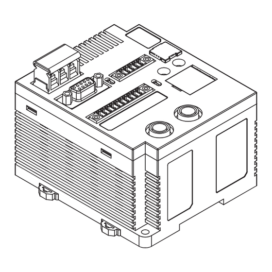
Page 15: Names And Functions Of Components
Name Description Power supply terminals Supply 24 VDC. Recommended power supply: S8VS-03024 (manufactured by OMRON) Ground terminal This is the ground terminal. Connected a dedicated ground line grounded to 100 W or less. ■ External I/O Port Connect the external I/O port to the external I/O signals. - Page 16 Section 1 Product Overview ■ RS-232C Port The RS-232C port is used for communications with the host device. The port conforms to RS-232C and can be connected to a computer, programmable controller, or other host device. ■ RS-422/RS-485 Port The RS-422/RS-485 port is used for communications with the host device. The port conforms to RS- 422/RS-485 and can be connected to a computer, programmable controller, or other host device.
- Page 17 Section 1 Product Overview ■ Main Display Indicators Name Color Description RUN/RST Green Lit when the ID Controller is operating normally. Lit when the external reset input is received. COMM Green Lit when communicating normally with the host device. Lit when an error is detected in communications with the host device. ■...
-
Page 18: System Configuration
Section 1 Product Overview System Configuration 1:1 Connections The host device is connected via RS-232C, RS-422, or RS-485. Programmable Controller (PLC) Computer RS-232C ID Controller V600-CA5D01/CA5D02 Read/Write Head Any V600-series Read/Write Heads and Data Carries can be connected. Data Carrier Pallet, etc. - Page 19 Section 1 Product Overview 1:N Connections with RS-232C Host Device Connection The host device is connected via RS-232C and then other ID Controllers are connected via RS-422/ RS-485. Programmable Controller (PLC) Computer RS-232C RS-422/RS-485 RS-422/RS-485 RS-422/RS-485 ID Controller V600-CA5D01/CA5D02 Read/Write Head Data Carrier Pallet, etc.
- Page 20 Section 1 Product Overview 1:N Connections with RS-422/RS485 Host Device Connection The host device is connected via RS-422 or RS-485 and then other ID Controllers are connected via RS-422/RS-485. Programmable Controller (PLC) Computer RS-422/RS-485 RS-422/RS-485 RS-422/RS-485 RS-422/RS-485 ID Controller V600-CA5D01/CA5D02 Read/Write Head Data Carrier Pallet, etc.
-
Page 21: Overall Flow Of Application
Section 1 Product Overview Overall Flow of Application Installation: p.22 Wiring: p.24 Setting ID Controller Communications: p.50 Testing Host Device Communications: p.58 Testing Data Carrier Communications: p.58 Checking Ambient Conditions: p.142 Communications and Operations Using Actual Commands: p.71 RFID System Operation Manual... - Page 22 Section 1 Product Overview MEMO RFID System Operation Manual...
-
Page 23: Section 2 Installation And Wiring
Section 2 Installation and Wiring Installation Wiring RFID System Operation Manual... -
Page 24: Installation
Section 2 Installation and Wiring Installation Observe the following precautions when installing the V600-CA5D01 or V600-CA5D02 ID Controller to enable proper performance of all functions. Installation Environment Do not install the ID Controller in the following locations. • Locations where the ambient operating temperature is not between 10 and 55C or locations where condensation may occur as the result of rapid variations in temperature •... - Page 25 10 mm between the ID Controllers to allow for cooling. 10 mm min. 10 mm min. End Plate End Plate Spacer Spacer Use at least two DIN Rail Spacers manufactured by OMRON. (One Spacer has a width of 5 mm.) Spacer PFP-S RFID System Operation Manual...
-
Page 26: Wiring
V1.25-MS3 Supply 24 VDC to the ID Controller. Make sure that the Recommended DC Power Supply: Compact, DIN-rail Mounting voltage fluctuation is within the range of 20.4 to 26.4 (Manufactured by OMRON) VDC (24 VDC+10%/15%). Model Output capacity... - Page 27 Section 2 Installation and Wiring Input and Output Lines ■ RESET Signal Input Precautions • Make sure that the input voltage of the RESET signal does not exceed the maximum voltage (26.4 V). If the maximum voltage is exceeded, the ID Controller may malfunction. •...
- Page 28 Section 2 Installation and Wiring ■ Connecting the Cable Use the connector provided with the ID Controller. Manufacturer Model Remarks Cable I/O lines 0.5 mm (equivalent to AWG20) Connector MC1.5/10-STF-3.5 Crimp terminals Connecting one line AI0.5-8WH per terminal Phoenix Contact Connecting two lines AI-TWIN20.5-8WH per terminal...
- Page 29 Request to send ❍ Can send (The example at the left is for connecting a shielded cable to the host device.) ■ Connecting to the Host Device ■ Connection Example to OMRON PLC Host device ID Controller Recommended Cable Model Manufacturer...
- Page 30 Use the communications connector provided with the ID Controller. The user must provide the con- necting cable and the host computer connector. The ID Controller connector is manufactured by OMRON and is protected from electromagnetic interference (EMI). Controller end Host device end...
- Page 31 Section 2 Installation and Wiring ■ Inserting and Removing the Connector • It is extremely important to hold the connector to attach and insert it properly. After inserting the connector, use a Phillips screwdriver and fully tighten the two lock screws. Recommended tightening torque: 0.3 Nm.
- Page 32 Section 2 Installation and Wiring RS-422/RS-485 Port Pin Arrangement • Pin Arrangement Pin No. Name Description RDA() Receive data RDB(+) Receive data SDA() Send data SDB(+) Send data Pin No. *Using RS-485 is possible by shorting pins 1 and 3 and pins 2 and 4, and changing the setting to RS-485.
- Page 33 Section 2 Installation and Wiring ■ Connecting between ID Controllers (1:N Connections) ■ RS-232C Host Device Connection SW6: ON SW6: ON SW6: OFF SW6: OFF Terminating Terminating Terminating resistance Terminating resistance resistance connected. resistance connected. not connected. not connected. RS-232C RS-422 RS-422 RS-422...
- Page 34 Section 2 Installation and Wiring ■ RS-422 Host Device Connection SW6: ON SW6: OFF SW6: OFF SW6: OFF Terminating Terminating resistance Terminating resistance Terminating resistance resistance connected. not connected. not connected. not connected. Host device RS-422 RS-422 RS-422 RS-422 Terminating resistance connected.
- Page 35 Section 2 Installation and Wiring ■ Connecting the Cable Use the connector provided with the ID Controller. The user must provide the connecting cable. Manufacturer Model Remarks Cable RS-422 signal line 0.5 mm (equivalent to AWG20) Connector MC1.5/5-STF-3.5 Crimp terminals Connecting one line AI0.5-8WH per terminal...
- Page 36 Section 2 Installation and Wiring USB Port The host device can be connected using an USB cable (series A and mini USB series B connectors). The USB port is not used for control operations. When constructing a system, always use the RS-232C or RS-422/RS- 485 port.
- Page 37 Section 2 Installation and Wiring Connecting the Series A Connector to the Host Device Align the connectors in the proper orientation and press straight in. Removing the Connector from the Host Device Close the software application at the host device and then pull the connector straight out.
- Page 38 Section 2 Installation and Wiring ■ Installing the USB Driver When using a USB cable to connect the ID Controller to the host device for the first time, the USB Driver must be installed on the host device. ■ Installing the USB Driver in the Computer The V600-CA5D01 and V600-CA5D02 supports Windows 2000 and Window XP operating systems.
- Page 39 Section 2 Installation and Wiring Select Search for a suitable driver for my device (recommended) and then click the Next Button. Select Specify a location and then click the Next Button. Click the Browse Button, and select the folder in which the downloaded file V600-CA5D_100.inf is saved.
- Page 40 Section 2 Installation and Wiring Click the Next Button. The following window will be displayed when software installation is completed. Click the Finish Button. RFID System Operation Manual...
- Page 41 Select Ports (COM & LPT), and confirm that OMRON RFID USB COM is displayed. The driver is correctly installed if this port is displayed. Communications with the ID Controller can be performed with the COM number displayed in parentheses after OMRON RFID USB COM.
- Page 42 Section 2 Installation and Wiring Windows XP (SP1) Turn ON the power to the personal computer and start Windows XP. Connect the ID Controller to the personal computer using the USB interface. Refer to USB Port for more information. p.34 Wait for the following window to be displayed.
- Page 43 Section 2 Installation and Wiring Click the Continue Anyway Button. The following window will be displayed when software installation has been completed. Click the Finish Button. RFID System Operation Manual...
- Page 44 Select Ports (COM & LPT), and confirm that OMRON RFID USB COM is displayed. The driver is correctly installed if this port is displayed. Communications with the ID Controller can be performed with the COM number displayed in parentheses after OMRON RFID USB COM.
- Page 45 Section 2 Installation and Wiring Windows Vista Turn ON the power to the personal computer and start Windows Vista. Connect the ID Controller to the computer via USB. For details on connection methods, refer to USB Port. p.34 Wait for the following window to be displayed. When the following window is displayed, select Locate and install driver software (recommended) Button.
- Page 46 Section 2 Installation and Wiring When the following window is displayed, select I don’t have the disc. Show me other options. But- ton. When the following window is displayed, select Browse my computer for driver software (advanced) Button. Click the Browse Button, and select the folder in which the downloaded file V680-CA5D_200.inf is saved.
- Page 47 Section 2 Installation and Wiring When the following window is displayed, select Install this driver software anyway Button. When the following window is displayed, installation is completed. Click the Close Button. The displays that actually appear depend on your computer environment. RFID System Operation Manual...
- Page 48 Select Ports (COM & LPT), and check that OMRON RFID USB COM is displayed. If the driver is correctly installed, the property window for the V680-CA5D will be displayed as follows: Communications with the ID Controller can be performed with the COM number displayed in parentheses after OMRON RFID USB COM.
- Page 49 Section 2 Installation and Wiring Read/Write Head Connection Port ■ Inserting and Removing the Connector Hold the rubber mold of the connector and insert the connector into the mating connector on the ID Controller. Push the connector straight in until it is locked. Ring The connector will not lock if it is pushed while holding the ring.
- Page 50 Section 2 Installation and Wiring MEMO RFID System Operation Manual...
-
Page 51: Section 3 Preparing Communications
Section 3 Preparing Communications Switch Settings Test Operation RFID System Operation Manual... -
Page 52: Switch Settings
Section 3 Preparing Communications Switch Settings Opening the Cover Insert the tip of a small flat-blade screwdriver into the notch in the cover and open the cover. Controller Number Switches (SW1 and SW2) DIP Switch SW3 DIP Switch SW4 Mode Switch (SW5) Terminating Resistance... - Page 53 Section 3 Preparing Communications Factory Settings Factory More Name Description setting information Controller Number Switch 1 (Upper digit: 0 to 9) Controller number 00 p.52 Controller Number Switch 2 (Lower digit: 0 to 9) SW3 pin 1 DIP switch/internal setting selector DIP switches enabled SW3 pin 2 Baud rate setting 1...
- Page 54 Section 3 Preparing Communications ■ Setting the Controller Number Switches (SW1 and SW2) ■ Controller Numbers It is necessary to be able to distinguish between ID Controller when more than one ID Controller is connected to a single host device. Each ID Controller is assigned a controller number for this purpose. The controller number is included in commands and responses for 1:N communications.
- Page 55 Section 3 Preparing Communications ■ DIP Switches (SW3 and SW4) ■ SW3 Pin 1: DIP Switch/Internal Setting Selector SW3 pin 1 Description DIP switches enabled. Internal settings enabled. Note: Switches SW1, SW2, SW3 pins 2 to 10, and SW4 pins 1 to 4 are enabled only when SW3 pin 1 is OFF (DIP switches enabled).
- Page 56 Section 3 Preparing Communications ■ SW4 Pin 1: Priority Mode Switch SW4 pin 1 Description Communications Distance Priority Mode Communications Time Priority Mode ■ SW4 Pin 2: Verify Setting SW4 pin 2 Description Verification enabled. Verification disabled. ■ SW4 Pin 3: Seven-segment Display Switch SW4 pin 3 Description End code display...
- Page 57 Section 3 Preparing Communications ■ Setting the Mode Switch Description RUN mode MAINTENANCE mode ■ Setting the Terminating Resistance When more than one ID Controller is connected in series to a single host device, the terminating resis- tance must be turned ON at the nodes (ID Controller or host device) on both ends of the main cable and turned OFF at the rest of the nodes.
- Page 58 Section 3 Preparing Communications Operating Modes The ID Controller has two modes: RUN mode and MAINTENANCE mode. ■ RUN mode In RUN mode, operation is performed according to commands from the host device and results are returned to the host device as responses. Host device Commands ID Controller...
-
Page 59: Test Operation
Section 3 Preparing Communications Test Operation • Check the power supply voltage and power supply terminal connections. Power turned ON. • Check the power supply voltage to the I/O terminals. • Check the POWER indicators on the ID Controller and Read/Write Head. Test operation of external •... - Page 60 Refer to TEST Command (TS) for more information on the TEST command. p.125 ■ Example for 1:N Communications The following command and response are for sending the test data "OMRON" to the ID Controller with controller number 2. Command Controller No.
-
Page 61: Section 4 Function
Section 4 Function Trigger Input (Lower Trigger Execution) Write Protect Function Data Carrier Service Life Detection Data Carrier Memory Check Function Write Command Memory RFID System Operation Manual... -
Page 62: Trigger Input (Lower Trigger Execution)
Section 4 Function Trigger Input (Lower Trigger Execution) The ID Controller uses trigger inputs to inform the ID Controller when to start processing the Data Carrier. After receiving a command from the host device, the ID Controller will wait until the rising edge of the trigger input and then start communications with the Data Carrier. -
Page 63: Write Protect Function
Section 4 Function Write Protect Function The write protect function prevents important data stored in the Data Carrier, such as the product type and model, from being overwritten by other data and lost. Use the following methods to set write protection after writing important data. Data Carriers with Built-in Battery (V600-D@KR@@ and V600-D@KF@@) ■... - Page 64 Section 4 Function ■ Settings to Not Write-protect Addresses Address Upper digit Lower digit 0002 0003 0004 0005 RFID System Operation Manual...
- Page 65 Section 4 Function ■ Setting Write Protection Function ■ Write Protection Setting Examples (2-Kbyte Memory Data Carrier) (1)Settings to Write-protect Addresses 0015H to 0120H (Start address < End address) Address 0000 Address 0015 0002 Write-protected area 0120 (HEX) 0003 07FF 0004 0005 (2)Settings to Write-protect 1 Byte...
- Page 66 Section 4 Function Data Carriers without Batteries (V600-D23P@@) ■ Setting Write Protection Function The write protect function is set by writing the final address to be protected in address 0000H of the Data Carrier's memory. The area between address 0001H and the write-protect end address will be write- protected.
-
Page 67: Data Carrier Service Life Detection
Section 4 Function Data Carrier Service Life Detection Data Carriers with Built-in Battery (V600-D@KR@@ and V600-D@KF@@) ■ Checking If the Battery Is Low ● Data Carriers with Built-in Batteries (Excluding V600-D2KR16) (1)A battery-low check for the Data Carrier can be performed only when special access is made. The battery-low check is performed by running a fixed current through the internal circuit of the Data Car- rier. - Page 68 Section 4 Function Data Carriers without Batteries (V600-D23P@@) MANAGEMENT DATA SUBTRACTION/LIMIT commands (MDS/MDL) can be used to determine whether the overwrite count for the EEPROM Data Carrier has been exceeded. By executing the MANAGEMENT DATA SUBTRACTION command (MDS), the number of overwrites is decremented from the data in the specified overwrite count control area, and whether the data has exceeded the limit is determined.
- Page 69 Section 4 Function ■ MDL Command The overwrite count control area consists of 3 bytes from the start address. The incremented value of the Upper digit Area start address overwrite count is written in this area, and if this value Middle digit 3 bytes is 100,000 (0186A0H) an end code of 76 will be...
-
Page 70: Data Carrier Memory Check Function
Section 4 Function Data Carrier Memory Check Function A memory check can be made using the MANAGEMENT DATA CHECK/CALCULATE commands (MDC/ MDK). A CRC (Cyclic Redundancy Check) code calculation, overwrite, and comparison are made, using the check block unit specified by the user. The CRC code is calculated from the generated polynomial expression + 1. -
Page 71: Write Command Memory
Section 4 Function Write Command Memory A write command executed by the ID Controller is recorded until either the next write command or until power is reset. The write commands include the WRITE, EXPANSION WRITE, AUTO WRITE, and POLLING AUTO WRITE commands. The recorded write command can be executed by using the WRITE PROCESSING REPEAT command. - Page 72 Section 4 Function RFID System Operation Manual...
-
Page 73: Section 5 Communications
Section 5 Communications Movement of Data Carriers and Command Status Command Format Communications Commands General Communications Subcommands Host Device Commands Other Commands End Codes RFID System Operation Manual... -
Page 74: Movement Of Data Carriers And Command Status
Movement of Data Carriers and Command Status Communications Control Protocol The host device communications control protocol conforms to the OMRON SYSWAY protocol. (1) Initially the host device has the right to send. When the host device sends a command, the right to send is transferred to the ID Controller. - Page 75 Section 5 Communications Command Reception Status The ID Controller can have the following status for commands sent from the host device. ■ Command Wait Status The ID Controller is in Command Wait Status when it is currently processing no command and is ready to receive any command from the host device.
- Page 76 Section 5 Communications Read/Write Functions ■ Read/Write Command Processing The read/write function is used for communications when the Data Carrier is motionless. Therefore, always be sure that the Data Carrier is at the specified position, i.e., in the communications area of the Read/Write Head. If the Data Carrier is missing, the ID Controller will return a response with an error code of 72 (Data Carrier missing).
- Page 77 Section 5 Communications Using the AUTO READ and AUTO WRITE Commands The READ and WRITE commands are normally used when Data Carriers are stopped. The Auto Commands are normally used when Data Carriers are moving. ● READ or WRITE Command ●...
- Page 78 Section 5 Communications Polling This section describes command processing when two Read/Write Heads are connected to one ID Controller. For normal Auto Commands, the ID Controller does not return a response until the Data Carrier approaches the specified Read/Write Head. This means that the communications path with the host device remains in the Busy Status, and the host device cannot send commands to the ID Control- ler's other Read/Write Head.
-
Page 79: Command Format
Section 5 Communications Command Format Command and Response Formats This section describes the format of commands sent from the host device to the ID Controller and the format of responses returned to the host device. ■ 1:1 Communications 1 frame = 522 characters max. Command code Data Terminator... - Page 80 Section 5 Communications For Expansion Commands, any command longer than 271 characters or any response longer than 256 characters is divided into multiple frames for communications. Only the last frame is sent with a terminator (*CR); all other frames are sent with a delimiter (CR). 1.
- Page 81 Section 5 Communications Data Code Specifications Whether the read or write data is treated as ASCII (or JIS 8 code) or hexadecimal values is specified in the command. ■ ASCII (JIS 8 Code) • One character of ASCII (JIS 8 code) data occupies 1 byte (1 •...
- Page 82 Section 5 Communications Command List There are four major groups of commands. ■ Communications Commands Communications Commands perform communications with Data Carriers. More informa- Command code Name Description tion READ Reads Data Carrier memory. p.82 WRITE Writes Data Carrier memory. p.84 EXPANSION READ Reads up to 2 KB of Data Carrier memory data by dividing the data into frames.
- Page 83 Section 5 Communications ■ Host Device Commands Host Device Commands are used to control the ID Controller. More informa- Command code Name Description tion TEST Used to check communications between the ID Controller and the host device. p.125 Returns the test message sent from the host device without any changes. CONTROLLER CON- Used to manipulate user I/O.
-
Page 84: Communications Commands
Section 5 Communications Communications Commands The commands used to perform communications with Data Carriers are described in this section. READ (RD) For READ the ID Controller reads data from Data Carrier memory. If there is no Data Carrier in the communications area, an error response with an error code of 72 (Data Carrier missing) will be returned. - Page 85 Section 5 Communications ■ 1:N Communications Command Data code R/W Head No. Command No. of read specifi- code bytes Controller No. Terminator cation Read area start address Data code specification Specifies the type of code in which to send the read data in the response. A: ASCII H: Hexadecimal R/W Head No.
- Page 86 Section 5 Communications WRITE (WT) For WRITE, the ID Controller writes data to Data Carrier memory. If there is no Data Carrier in the communications area, an error response with an error code of 72 (Data Carrier missing) will be returned.
- Page 87 Section 5 Communications ■ 1:N Communications Command Data code R/W Head No. Command specifica- Controller No. Write data Terminator Write area start address code tion Data code specification Specifies the type of code in which the write data is being sent. A: ASCII H: Hexadecimal R/W Head No.
- Page 88 Section 5 Communications EXPANSION READ (XR) For EXPANSION READ, the ID Controller reads up to 2 KB of Data Carrier memory data by dividing the data into frames. If there is no Data Carrier in the communications area, an error response with an error code of 72 (Data Carrier missing) will be returned.
- Page 89 Section 5 Communications More Than 250 Characters in Read Data ID Controller Host device 1 frame = 256 characters max. per frame Start address No. of read bytes 250 characters Read data 1 Frame 1 254 characters Read data 2 Frame 2 Read data n-1 Frame...
- Page 90 Section 5 Communications ■ 1:N Communications Command Data code R/W Head No. Command specifica- Read area start address Controller No. No. of read bytes Terminator code tion Data code specification Specifies the type of code in which to send the read data in the response. A: ASCII H: Hexadecimal R/W Head No.
- Page 91 Section 5 Communications EXPANSION WRITE (XW) For EXPANSION WRITE, the ID Controller writes up to 2 KB to Data Carrier memory data by dividing the data into frames. If there is no Data Carrier in the communications area, an error response with an error code of 72 (Data Carrier missing) will be returned.
- Page 92 Section 5 Communications ■ Frame Division Divided the command into frames as shown below if the command is longer than 271 characters. Frame Division 1. Divide the command so that each frame is 271 characters or less. 2. Attach a terminator (*CR) to the last frame (frame n). Attach a delimiter (CR) to all other frames. 3.
- Page 93 Section 5 Communications ■ 1:N Communications Command Frame 1 Data code R/W Head No. Command specifica- Controller No. Write area start address Write data Terminator code tion 1 or 2 Frame 2 and Later Frames Controller No. Write data Terminator 1 or 2 Data code specification Specifies the type of code in which the write data is being sent.
- Page 94 Section 5 Communications ■ Frame Dividing Method Divided the command into frames as shown below if the command is longer than 271 characters. 1. Divide the command so that each frame is 271 characters or less. 2. Attach a terminator (*CR) to the last frame (frame n). Attach a delimiter (CR) to all other frames. 3.
- Page 95 Section 5 Communications EXPANDED READ (ER) For EXPANDED READ, the ID Controller reads up to 8 KB of data from Data Carrier memory. If there is no Data Carrier in the communications area, an error response with an error code of 72 (Data Carrier missing) will be returned.
- Page 96 Section 5 Communications ■ 1:N Communications Command Data code R/W Head No. specifica- Read area start address Controller No. No. of read bytes Terminator Command code tion Data code specification Specifies the type of code in which to send the read data in the response. A: ASCII H: Hexadecimal R/W Head No.
- Page 97 Section 5 Communications AUTO READ (AR) For AUTO READ, the ID Controller waits for a Data Carrier to approach and then reads data from Data Carrier memory. The ID Controller will return a response to the host device when communications with the Data Carrier have been completed.
- Page 98 Section 5 Communications ■ 1:N Communications Command Data code R/W Head No. No. of read specifica- Controller No. Read area start address F C S Terminator Command code bytes tion A / H 1 / 2 Data code specification Specifies the type of code in which to send the read data in the response. A: ASCII H: Hexadecimal R/W Head No.
- Page 99 Section 5 Communications AUTO WRITE (AW) For AUTO WRITE, the ID Controller waits for a Data Carrier to approach and then writes data to Data Carrier memory. The ID Controller will return a response to the host device when communications with the Data Carrier have been completed.
- Page 100 Section 5 Communications ■ 1:N Communications Command Data code R/W Head No. specifica- Controller No. Command code Write area start address Terminator tion Write data Data code specification Specifies the type of code in which the write data is being sent. A: ASCII H: Hexadecimal R/W Head No.
- Page 101 Section 5 Communications DATA FILL (DF) For DATA FILE, the ID Controller waits for a Data Carrier to approach and then fills Data Carrier memory with the specified number of write bytes from the start write address specified in the command.
- Page 102 Section 5 Communications ■ Example 1 The following example fills 6 bytes (0006H) of memory starting from address 0030H with 0101H for a Data Carrier in which the same data as the address is written. Command Data code R/W Head No. No.
- Page 103 Section 5 Communications ■ 1:N Communications Command Data code R/W Head No. No. of write specifica- bytes Specified data Controller No. F C S Terminator tion Write area start address Command code A / H 1 / 2 2 or 4 Data code specification Specifies the type of code in which to send the read data in the response.
- Page 104 Section 5 Communications AUTO DATA FILL (AF) For AUTO DATA FILL, the ID Controller waits for a Data Carrier to approach and then fills Data Carrier memory with the specified number of write bytes from the start write address specified in the command.
- Page 105 Section 5 Communications ■ 1:N Communications Command Data code R/W Head No. No. of write specifica- Controller No. bytes Specified data Write area start address F C S Terminator Command code tion A / H 1 / 2 2 or 4 Data code specification Specifies the type of code in which to send the read data in the response.
- Page 106 Section 5 Communications COPY (CP) For COPY, the ID Controller writes data read from Data Carrier memory by one Read/Write Head to the memory of a Data Carrier in the communications area of the other Read/Write Head. If the source Data Carrier is missing, the ID Controller will return a response with an error code of 72 (Data Carrier missing).
- Page 107 Section 5 Communications ■ 1:N Communications Command R/W Head No. Data code specifica- Copy destination write start address Terminator Read area start address No. of bytes to copy F CS Controller No. Command code tion 1 / 2 Data code specification Always “H”...
- Page 108 Section 5 Communications AUTO COPY (AP) For AUTO COPY, the ID Controller waits until a Data Carrier approaches and then Writes data read from Data Carrier memory by one Read/Write Head to the memory of a Data Carrier in the communications area of the other Read/Write Head.
- Page 109 Section 5 Communications ■ 1:N Communications Command R/W Head No. Data code specifica- tion Read area start address No. of bytes to copy Copy destination write start address Terminator Controller No. Command code F CS 1 / 2 Data code specification Always “H”...
- Page 110 Section 5 Communications POLLING AUTO READ (PR) For POLLING AUTO READ, the ID Controller immediately returns a response informing the host device that the command has been received (end code: 74 = polling command received). The ID Controller then waits for a Data Carrier to approach and reads data from Data Carrier memory. During this time, the host device can check the results of command processing by using a subcommand.
- Page 111 Section 5 Communications Subcommands Check/end specification R/W Head No. Terminator Command code Check/end specification Specifies checking processing results or ending (terminating) the command. C: Check processing E: End R/W Head No. Specifies the Read/Write Head with which to communicate. 1: Read/Write Head 1 2: Read/Write Head 2 Subcommand Responses Command code...
- Page 112 Section 5 Communications ■ 1:N Communications Command Data code R/W Head No. No. of specifica- Controller No. Read area start address read bytes Terminator Command code tion Data code specification Specifies the type of code in which to send the read data in the response. A: ASCII H: Hexadecimal R/W Head No.
- Page 113 Section 5 Communications Subcommands Check/end specification R/W Head No. Controller No. Terminator Command code Check/End specification Specifies checking processing results or ending (terminating) the command. C: Check processing E: End R/W Head No. Specifies the Read/Write Head for querying or canceling. 1: Read/Write Head 1 2: Read/Write Head 2 Subcommand Responses...
- Page 114 Section 5 Communications POLLING AUTO WRITE (PW) For POLLING AUTO WRITE, the ID Controller immediately returns a response informing the host device that the command has been received (end code: 74 = polling command received). The ID Controller then waits for a Data Carrier to approach and writes data to Data Carrier memory. During this time, the host device can check on the result of the command processing by using a subcommand.
- Page 115 Section 5 Communications Check/End specification Subcommands R/W Head No. Terminator Command code Check/End specification Specifies checking processing results or ending (terminating) the command. C: Check processing E: End R/W Head No. Specifies the Read/Write Head for querying or canceling. 1: Read/Write Head 1 2: Read/Write Head 2 Subcommand Responses Command code...
- Page 116 Section 5 Communications ■ 1:N Communications Command Data code R/W Head No. specifica- Controller No. Write data Command code tion Write area start address Terminator Data code specification Specifies the type of code in which the write data is being sent. A: ASCII H: Hexadecimal R/W Head No.
- Page 117 Section 5 Communications Check/End specification Subcommands R/W Head No. Controller No. Terminator Command code Check/End specification Specifies checking processing results or ending (terminating) the command. C: Check processing E: End R/W Head No. Specifies the Read/Write Head for querying or canceling. 1: Read/Write Head 1 2: Read/Write Head 2 Subcommand Responses...
- Page 118 Section 5 Communications MANAGEMENT DATA CHECK/CALCULATE (MDC/MDK) These commands make it possible to write and verify the CRC code in a check block that the user des- ignates. The CRC code is calculated using the formula X + 1. ■ 1:1 Communications Command Process R/W Head No.
- Page 119 Section 5 Communications ■ 1:N Communications Command Process R/W Head No. No. of check specifi- Command code block bytes Check block start address Controller No. cation Terminator Process specification Specifies the check processing to perform. C: Compare check code K: Calculate check code R/W Head No.
- Page 120 Section 5 Communications MANAGEMENT DATA SUBTRACTION/LIMIT (MDS/MDL) These command are used to control the number of times that a Data Carrier without a battery can be overwritten. By updating the management area designated by the user, the user can determine whether the number of times the EEPROM has been overwritten exceeds the set number.
- Page 121 Section 5 Communications ■ 1:N Communications Command Mode R/W Head No. Decrement/ specifi- Controller No. increment count Command code Area start address Terminator cation Mode specification Specifies the check processing to perform. S: Subtraction (The number of overwrites can be set to any value up to 16,700,000 overwrites.) (See note.) L: Addition (The overwrite limit is always 100,000 overwrites.) R/W Head No.
- Page 122 Section 5 Communications WRITE PROCESSING REPEAT (RP) WRITE PROCESSING REPEAT executes the most recently executed Write Command. ■ 1:1 Communications Command Command code Terminator Response Command code End code Terminator Command code The command code of the most recently executed Write Command. End code Indicates the results of command execution.
- Page 123 Section 5 Communications ■ 1:N Communications Command Controller No. Command code Terminator Response Controller No. Command code End code Terminator Command code The command code of the most recently executed Write Command. End code Indicates the results of command execution. 00: Normal end Refer to End Codes for more information.
-
Page 124: General Communications Subcommands
Section 5 Communications General Communications Subcommands These commands are used in combination with a Communications Command and cannot be used alone to execute communications with Data Carriers. COMMAND PROCESSING TERMINATE (AA) COMMAND PROCESSING TERMINATE is used to cancel command processing and return to Command Wait Status for any command except for Polling Commands. - Page 125 Section 5 Communications ■ 1:N Communications Command Controller No. Command code Terminator Response Controller No. End code Terminator Command code End code Indicates the results of command execution. 14: Auto or Normal Command processing has not been executed. 75: Processing was canceled before a Data Carrier was detected. 76: Processing was canceled during read/write processing with a Data Carrier.
- Page 126 Section 5 Communications ABORT (XZ) If the ID Controller does not return a response due to a problem during host communications or during communications with a Data Carrier, the ABORT command can be executed to restore the ID Controller to the Command Wait Status. No response will be returned to the ABORT command.
-
Page 127: Host Device Commands
Section 5 Communications Host Device Commands TEST (TS) For TEST, the ID Controller returns the test message sent from the host device without any changes. Use TEST to text communications between the host device and ID Controller. ■ 1:1 Communications Command Command code Test data... - Page 128 Section 5 Communications CONTROLLER CONTROL (CC) CONTROLLER CONTROL is used to manipulate user I/O. ■ 1:1 Communications Command OUT1 OUT2 Command code Process code control control Terminator Process code Always “00”. OUT1/OUT2 control 0: No operation 1: Turn ON output 2: Turn OFF output Response Input status Output status...
- Page 129 Section 5 Communications ■ 1:N Communications Command OUT1 OUT2 Controller No. control control Terminator Command code Process code Process code Always “00”. OUT1/OUT2 control 0: No operation 1: Turn ON output 2: Turn OFF output Response End code Output status Command code Input status Terminator...
- Page 130 Section 5 Communications ERROR INFORMATION READ (CF) ERROR INFORMATION READ reads the most recent error information. ■ 1:1 Communications Command Command code Process code Terminator Process code Specifies the Read/Write Head with which to communicate. 00: Read error information 01: Clear error information Response Command code End code...
- Page 131 Section 5 Communications ■ 1:N Communications Command Controller No. Command code Process code Terminator FC S Process code Specifies the Read/Write Head with which to communicate. 00: Read error information 01: Clear error information Response Controller No. Command code End code Most recent error log information Terminator End code...
- Page 132 Section 5 Communications COMMUNICATIONS CONDITIONS SETTING (TR) TR sets conditions for serial communications. After modifying a setting it is necessary to restart the ID Controller or execute the ABORT command (XZ) to enable operating with the modified setting. Setting communications conditions with this command is enable only when internal settings are enabled (i.e., when SW3 pin 1 is ON).
- Page 133 Section 5 Communications ■ 1:N Communications Command Parity Baud Data Stop bit rate length check setting Controller No. Terminator Command code setting setting setting Baud rate setting Sets the baud rate. 0: 1,200 bps 1: 2,400 bps 2: 4,800 bps 3: 9,600 bps 4: 19,200 bps 5: 38,400 bps...
- Page 134 Section 5 Communications PARAMETER SETTING (SP) PARAMETER SETTINGS sets communications conditions for Data Carriers. It can be used to set all ID Controller parameters. ■ 1:1 Communications Command Parameter data Command code Process code (only when changing parameters) Terminator (Upper digit) (Lower digit) 0 to 4 Process code upper digit Specifies the processing to perform on the parameters.
- Page 135 Section 5 Communications ■ 1:N Communications Command Parameter Controller No. Process code (only when changing parameters) Terminator Command code (upper digit) (lower digit) 0 to 4 Process code upper digit Specifies the processing to perform on the parameters. 0: Change internal settings. 1: Read internal settings.
-
Page 136: Other Commands
Section 5 Communications Other Commands Undefined Command Response (IC) This response is returned when the ID Controller cannot interpret the command code. ■ 1:1 Communications Response Command code Terminator ■ 1:N Communications Response Controller No. Command code Terminator Error Response When an error occurs during communications with the host computer or during communications with a Data Carrier, an end code is used to indicate the nature of the error. -
Page 137: End Codes
Section 5 Communications End Codes End codes are given by two hexadecimal digits. Type End code Name Normal Normal end code Polling Command received, Polling Command Check (no results) Auto Command canceled before a Data Carrier was detected. Polling Command canceled before a Data Carrier was detected. Normal end code for a MANAGEMENT DATA CHECK/CALCULATE command or MANAGEMENT DATA SUBTRACTION/LIMIT command (not an error) Auto Command canceled after a Data Carrier was detected. - Page 138 Section 5 Communications MEMO RFID System Operation Manual...
-
Page 139: Section 6 Troubleshooting
Section 6 Troubleshooting Diagnostic Functions Error Lists Troubleshooting Maintenance and Inspection Troubleshooting Flowcharts RFID System Operation Manual... -
Page 140: Diagnostic Functions
Section 6 Troubleshooting Diagnostic Functions Types of Errors ■ Fatal Operation Errors If a CPU error or internal memory error occurs, the RUN/RST indicator will go OFF and the RUN output will turn OFF. If an internal memory error occurs, the COM indicator will also light red. If an antenna power supply voltage error occurs, the RUN/RST indicator will light green. -
Page 141: Error Lists
Section 6 Troubleshooting Error Lists Host communications error Error Type Name Description code Parity error An error occurred in communications between the host device and ID Controller. • Error in setting the communications format Framing error Errors in • Malfunction due to noise Overrun error communica- tions with... - Page 142 Section 6 Troubleshooting System Errors Error Name Description code Antenna power supply The voltage supplied to the Read/Write Head from the ID Controller has dropped. voltage error • Prepare a replacement ID Controller. A memory may have occurred in the ID Controller or noise may have caused an error. •...
-
Page 143: Troubleshooting
Section 6 Troubleshooting Troubleshooting There are four major causes of ID Controller problems: • Influence of noise••••••••••••••••••Take countermeasures against noise. • Malfunctioning of external devices •••••••Repair is required. • Malfunctioning of ID Controller • Other ■ Influence of Noise If the system malfunctions due to noise, take appropriate countermeasures against noise by referring to the following table. -
Page 144: Maintenance And Inspection
Section 6 Troubleshooting Maintenance and Inspection To keep the ID Controller in the best condition, the ID Controller should be inspected daily or periodically. Although the ID Controller consists of semiconductor devices, the following problems may occur depending on the environment and conditions in which the ID Controller is operated. -
Page 145: Troubleshooting Flowcharts
Section 6 Troubleshooting Troubleshooting Flowcharts If a malfunction has occurred, carefully investigate the surrounding conditions and check whether the trouble persists or is related to other equipment. Then troubleshoot the malfunction according to the following flowcharts. Main Check Flowchart Make a decision for the main check Main Check Flowchart flowchart depending on the nature of the error. - Page 146 Section 6 Troubleshooting Systems Check Flowchart START Connector and cable connections Power ON Connect correctly Not lit Rated voltage RUN/RST indicator? supplied? Lit red COMM indicator? Rated voltage supplied Not lit Turn ON reset input. Lit red RUN/RST indicator? Reset power. Reset Data Carrier communications conditions with SP command.
- Page 147 Section 6 Troubleshooting Application Conditions and External Environment Check START Refer to Maintenance Application and Inspection. conditions OK? p.142 Refer to Noise Troubleshooting. environment p.141 RFID System Operation Manual...
- Page 148 Section 6 Troubleshooting Host Communications Check START Connector Communications Response wiring OK? returned? conditions OK? Correct connector Set the same commu- wiring. nications conditions. Communications Monitor display = Noise environment 10, 11, or 12? conditions OK? Set the same commu- Take countermeas- nications conditions.
- Page 149 Section 6 Troubleshooting Data Carrier Communications Check START Distance More than Monitor display one Data Carrier in between Data Carrier Travel speed OK? Data Carrier OK? communications and Head OK? = 70? area? Adjust the distance between the Only allow 1 Data Carrier Reduce the travel Replace Data Carrier.
- Page 150 Section 6 Troubleshooting MEMO RFID System Operation Manual...
-
Page 151: Section 7 Appendix
Section 7 Appendix Specifications and Dimensions Characteristics According to Application Conditions Data Carrier Memory Map Data Carrier Memory Capacities and Memory Types ASCII Table Degree of Protection RFID System Operation Manual... -
Page 152: Specifications And Dimensions
Section 7 Appendix Specifications and Dimensions General Specifications Specification Item V600-CAD01 V600-CAD02 Power supply voltage 24 VDC (15% to 10%) Power consumption/current consumption Power consumption: 15 W, current consumption: 0.8 A 10 to 55C (with no icing) Ambient operating temperature Ambient operating humidity 25% to 85% (with no condensation) 25 to 65C (with no icing) - Page 153 Section 7 Appendix I/O Specifications ● Input Specifications (RST, TRG/IN1, and TRG/IN2) ● Output Specifications (RUN, BUSY, ERROR, OUT1, and OUT2) Input voltage 24 VDC +10% (including ripple)/ Maximum switch- 24 VDC +10% (including ripple)/15% 15% (PNP or NPN) ing capacity 100 mA photo MOS outputs (PNP or NPN) Input impedance 2.2 k...
- Page 154 Section 7 Appendix Dimensions Two, M4 Mounting Hole Dimensions 95±0.2 Two, 4.5-dia. mounting holes (Unit: mm) RFID System Operation Manual...
-
Page 155: Characteristics According To Application Conditions
Section 7 Appendix Characteristics According to Application Conditions Communications Area Diagram (Reference) The communications area of the V600-CA5D02 is shown below. The communications area depends on installation and environment conditions. • V600-H11 to V600-D23P66N The communications diagram indicates the communications area consisting of a flat plane perpendicular to the antenna and running through the center of the Read/Write Head. - Page 156 Section 7 Appendix Host Communications Time and Data Carrier Communications Time ■ Data Carrier Communications Time • The communications time with a Data Carrier depends on the type of Data Carrier being used (with or without a built-in battery). • The communications time of Data Carriers without batteries also depends on the communications mode setting.
- Page 157 Section 7 Appendix 2)Communications Time Priority Mode (SW4 Pin 1 OFF) ● Communications Time with Data Carriers 2500 2000 1500 (AUTO) WRITE Calculations 1000 Communications time (ms) Reading T=1.8N+79.0 Writing T=7.1N+180.4 (AUTO) WRITE N: No. of bytes processed No. of bytes processed RFID System Operation Manual...
- Page 158 Section 7 Appendix ■ TAT (Turn Around Time) • The TAT depends on the type of Data Carrier being used (with or without a built-in battery). • The TAT of Data Carriers without batteries also depends on the communications mode setting. •...
- Page 159 Section 7 Appendix Data Carriers with Built-in Batteries (Reference) ● TAT 1000 (AUTO) WRITE Calculations TAT (ms) Reading T=2.9N+69.8 (AUTO) READ Writing T=5.3N+105.6 N: No. of bytes processed No. of bytes processed (bytes) Data Carriers without Built-in Batteries (Reference) 1)Communications Distance Priority Mode (SW4 Pin 1 OFF) ●...
- Page 160 Section 7 Appendix Data Carrier Speed Use Auto Command and Polling Commands to communicate with moving Data Carriers. The maximum speed of Data Carrier when executing these commands can be calculated simply using the following formula. D (Distance traveled in the transmission range (m)) ...
-
Page 161: Data Carrier Memory Map
Section 7 Appendix Data Carrier Memory Map Data Carriers without Batteries Address Data 0000 Write protection setting area 0001 0002 0003 User area 1 byte Data Carriers with Built-in Batteries Address Data 0000 Manufacturing data area 0001 0002 Write protection setting area 0005 0006 00FF... -
Page 162: Data Carrier Memory Capacities And Memory Types
Section 7 Appendix Data Carrier Memory Capacities and Memory Types (As of September 2005) Memory capacity Model Memory type Service life (user memory) V600-D8KR12 V600-D8KR13 8 KB SRAM 5 to 8 years (See note.) V600-D8KR04 V600-D2KR16 SRAM (replace- 2 years at 25C 2 KB able battery) V600-D23P53... -
Page 163: Ascii Table
Section 7 Appendix ASCII Table Upper digit b8 to b5 0000 0001 0010 0011 0100 0101 0110 0111 1000 1001 1010 1011 1100 1101 1110 1111 Lower digit Column b4 to b1 0000 TC7(DLE) 0001 TC1(SOH) 0010 TC2(STX) 0011 TC3(ETX) 0100 TC4(EOT) 0101... -
Page 164: Degree Of Protection
Section 7 Appendix Degree of Protection Ingress protection degrees (IP-@@) are determined by the following tests. Be sure to check the sealing capability under the actual operating environment and conditions before actual use. ■ IEC (International Electrotechnical Commission) Standards (IEC 60529 November 1989) First Number: Degree of Protection from Solid Materials Degree Protection... - Page 165 Section 7 Appendix Degree Protection Test method (with fresh water) Protection against sprin- Protects against sprinkled Water is sprinkled at a Water rate per hole: kled water water approaching at a maxi- maximum angle of 60 to 0.07l/min mum angle of 60 from verti- the left and right from cal towards the product.
-
Page 166: Revision History
Revision History A manual revision code appears as a suffix to the catalog number on the front cover of the manual. Man No. Z239-E1-03A Revision code Revision code Date Revised contents January 2006 Original production August 2007 Page 148: Specifications changed September 2008 Made revisions related to design changes. - Page 167 The Netherlands IL 60173-5302 U.S.A. Tel: (31)2356-81-300/Fax: (31)2356-81-388 Tel: (1) 847-843-7900/Fax: (1) 847-843-7787 © OMRON Corporation 2009 All Rights Reserved. OMRON (CHINA) CO., LTD. OMRON ASIA PACIFIC PTE. LTD. In the interest of product improvement, Room 2211, Bank of China Tower, No.
Need help?
Do you have a question about the V600 Series and is the answer not in the manual?
Questions and answers