
Subscribe to Our Youtube Channel
Related Manuals for Kramer EXT3-C-XR-TR


Summary of Contents for Kramer EXT3-C-XR-TR
- Page 1 USER MANUAL MODEL: EXT3-21-XR-TR HDMI & USB 2X1 Switcher Extender P/N: 2900-301697 Rev 2 www.kramerav.com...
-
Page 2: Table Of Contents
Kramer Electronics Ltd. Contents Introduction Getting Started Overview Typical Applications Defining EXT3-21-XR-TR HDMI & USB 2X1 Switcher Extender Mounting EXT3-21-XR-TR Connecting EXT3-21-XR-TR Connecting to EXT3-21-XR-TR via RS-232 Operating and Controlling EXT3-21-XR-TR Principles of Operation Using Front and Rear Panel Buttons... -
Page 3: Introduction
Kramer Electronics Ltd. Introduction Welcome to Kramer Electronics! Since 1981, Kramer Electronics has been providing a world of unique, creative, and affordable solutions to the vast range of problems that confront the video, audio, presentation, and broadcasting professional on a daily basis. In recent years, we... -
Page 4: Overview
European Advanced Recycling Network (EARN) and will cover any costs of treatment, recycling and recovery of waste Kramer Electronics branded equipment on arrival at the EARN facility. For details of Kramer’s recycling arrangements in your particular country go to our recycling pages at www.kramerav.com/il/quality/environment. - Page 5 Kramer Electronics Ltd. Advanced and User-friendly Operation – • Controllable coupled−signals switching of both Hybrid-meeting Collaborative Switching AV and USB host inputs, for concurrent connection with AV output and room USB devices, allows collaborative hybrid meeting where multiple meeting participants are switched to share their content with both room and online meeting participants.
-
Page 6: Typical Applications
Kramer Electronics Ltd. • Cost–effective Maintenance - Status LED indicators for HDMI, Loop, HDBT, and USB active host ports, facilitate easy local maintenance and troubleshooting. – • Comprehensive and Cost–effective Management Local panel status LED, remote IP−driven firmware upgrade and management via user−friendly embedded web pages,... -
Page 7: Defining Ext3-21-Xr-Tr Hdmi & Usb 2X1 Switcher Extender
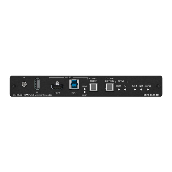
Kramer Electronics Ltd. Defining EXT3-21-XR-TR HDMI & USB 2X1 Switcher Extender This section defines EXT3-21-XR-TR. Configuring the device as transmitter (Tx) or receiver (Rx, default) is done via the front panel button or the embedded webpages settings (see Setting Extender Operation Modes on page 33). - Page 8 Kramer Electronics Ltd. Feature Function STATUS Indicates device status: LED Color Indicates Off (Dark) Device is powered and no active source connected. Blue Device is powered, and an active source is connected. Green Device is powered, an active source and acceptor are connected.
- Page 9 Kramer Electronics Ltd. Figure 2: EXT3-21-XR-TR HDMI & USB 2X1 Switcher ExtenderRear Panel Feature Function HDBT PoE RJ-45 Connector Connect to the HDBT RJ-45 connector on a paired receiver/transmitter device (for example, a second EXT3-21-XR-TR device) that receives or provides PoE.
-
Page 10: Mounting Ext3-21-Xr-Tr
Kramer Electronics Ltd. Mounting EXT3-21-XR-TR This section provides instructions for mounting EXT3-21-XR-TR. Before installing, verify that the environment is within the recommended range: • Operation temperature – 0 to 40C (32 to 104F). • Storage temperature – -40 to +70C (-40 to +158F). -
Page 11: Connecting Ext3-21-Xr-Tr
Kramer Electronics Ltd. Connecting EXT3-21-XR-TR Always switch off the power to each device before connecting it to your EXT3-21-XR-TR. After connecting your EXT3-21-XR-TR, connect its power and then switch on the power to each device. Figure 3: Connecting to the EXT3-21-XR-TR Rear Panels... - Page 12 6. To control the room devices via Ethernet, connect the following: ▪ On the EXT3-C-XR-T transmitter LAN port, connect a touch panel designed to operate Kramer Control (for example, KT-208). ▪ EXT3-21-XR-TR receiver side connect the 1G LAN PoE port to LAN.
-
Page 13: Connecting To Ext3-21-Xr-Tr Via Rs-232
Kramer Electronics Ltd. Connecting to EXT3-21-XR-TR via RS-232 You can connect to EXT3-21-XR-TR via an RS-232 connection using, for example, a PTZ camera, PC, or display. EXT3-21-XR-TR features an RS-232 3-pin terminal block connector allowing the RS-232 to control either the EXT3-21-XR-TR or a serially controllable device. -
Page 14: Operating And Controlling Ext3-21-Xr-Tr
Kramer Electronics Ltd. Operating and Controlling EXT3-21-XR-TR Principles of Operation • Pair-synched Coupled AV+USB Auto Switching on page 12. • Coupled or Individual AV+USB Switching on page 14. • Flexible EXT3-21-XR-TR Auto Switching Policy on page 15. • Online Meeting Systems Integration on page 15. - Page 15 Kramer Electronics Ltd. • Room-located participants use the Tx-connected room USB devices for collaborating and sharing content via the room PC/NUC. Figure 4: RBM Scenario BYOM scenario: • Room-located hybrid meeting participants bring their portable laptops running their own meeting app, such as Microsoft Teams.
- Page 16 Kramer Electronics Ltd. • Room-located participants use the Tx-connected room USB devices for collaborating and sharing content via the laptop. Figure 5: BYOM Scenario Same synched pair operation applies also to mixed pairs of any Tx and Rx devices, providing that each device supports the pair-synced operation feature...
- Page 17 Kramer Electronics Ltd. Flexible EXT3-21-XR-TR Auto Switching Policy This feature is relevant only for the receiver switcher mode. Set the inputs switching policy to connected output and room devices to: • Manual – Select an input manually and switching occurs whether input live signals are present or not.
-
Page 18: Using Front And Rear Panel Buttons
Kramer Electronics Ltd. I/O control commands (converted from the client received IP messages) to the I/O controlled connected devices and distributes their received detected triggers to all connected clients. (see Setting Control Gateway Properties on page 39). Flexible Remote Buttons Control Remote contact-closure buttons can be connected to the I/O ports, for easy end user control of device functions by button press and release operation. -
Page 19: Operating Via Ethernet
Kramer Electronics Ltd. Operating via Ethernet • Directly to the PC using a crossover cable (see Connecting Ethernet Port Directly to a on page 17). • Via a network switch or router, using a straight-through cable (see Connecting Ethernet Port via a Network Hub on page 19). - Page 20 Kramer Electronics Ltd. 5. Click Properties. The Internet Protocol Properties window relevant to your IT system appears as shown in Figure 7 Figure Figure 7: Internet Protocol Version 4 Properties Window Figure 8: Internet Protocol Version 6 Properties Window 6. Select Use the following IP Address for static IP addressing and fill in the details as...
- Page 21 Kramer Electronics Ltd. For TCP/IPv4 you can use any IP address in the range 192.168.1.1 to 192.168.1.255 (excluding default 192.168.1.39 fallback address) that is provided by your IT department. Figure 9: Internet Protocol Properties Window 7. Click OK. 8. Click Close.
-
Page 22: Using Embedded Web Pages
Kramer Electronics Ltd. Using Embedded Web Pages EXT3-21-XR-TR enables you to configure settings via Ethernet using built-in, user-friendly web pages. The Web pages are accessed using a Web browser and an Ethernet connection. You can also configure EXT3-21-XR-TR via Protocol 3000 commands (see... - Page 23 Kramer Electronics Ltd. 2. Enter the Username (default = Admin) and Password (default = Admin) and click Sign in. The default web page appears. Figure 11: Default Landing Page EXT3-21-XR-TR – Using Embedded Web Pages...
- Page 24 Kramer Electronics Ltd. 3. Click the arrow at the top of the navigation list to view the menu items in detail. Figure 12: Pages and Tabs Navigable List 4. Click the Navigation Pane on the left side of the screen to access the relevant web page.
-
Page 25: Routing Operations
Kramer Electronics Ltd. Routing Operations This section details the following actions: • Routing an Input to an Output on page 23. • Setting Analog Audio Output Volume Level on page 27. Routing an Input to an Output When routing any of the inputs to the output, you can set both inputs to route the AV signal together with the USB signal (USB follows video coupled routing) or to independently route each individual signal. - Page 26 Kramer Electronics Ltd. AV Routing To route the video inputs to the outputs: 1. Go to the Routing Operation page. Figure 13:Rx Mode Routing Page 2. Perform the following functions: ▪ Click an Input/Output cross-point (see Routing AV and USB Host Signals on page 26).
- Page 27 Kramer Electronics Ltd. To select Local Active Host: 1. Go to the Routing Operation page. 2. Click the Input/Output cross-point HDMI 1USB Host shown in (see Figure 14). Using the local active host, you now control USB devices connected to all local devices.
- Page 28 Kramer Electronics Ltd. To select Remote Active Host: 1. Go to the Routing Operation page. 2. Click the Input/Output cross-point HDBT 2 USB Host shown in (Figure 16). Using the remote active host, you now remotely control all USB connected devices connected to all local and remote devices.
-
Page 29: Setting Av Properties
Kramer Electronics Ltd. Setting Analog Audio Output Volume Level To set the audio output volume level: 1. Go to the Routing Operation page. 2. Next to Analog output volume (dB) click 3. Set the audio volume level: ▪ using the slider next to Analog output volume (dB, from -80 to 20), or ▪... - Page 30 Kramer Electronics Ltd. 3. Click and drag a host input between high and low to change the priorities. Figure 19: Changing Input Priorities 4. Click SET VIDEO. AV input priorities are set. Settings AV Signal Properties EXT3-21-XR-TR enables setting the audio and video signal properties.
- Page 31 Kramer Electronics Ltd. To set audio and video signal: 1. Go to the Audio Video Settings page. The Audio Video Settings page appears. Figure 20: Audio Video Settings Perform the following actions: • Label – Change the name of an input or the output as it appears on the Routing page and EDID management page.
-
Page 32: Device Settings And Maintenance
Kramer Electronics Ltd. To copy the EDID to the inputs: 1. Go to the EDID Management page. Figure 21: EDID Management Page 2. Under Step 1, select the EDID source (the output, any of the inputs, default or custom EDID file). - Page 33 Kramer Electronics Ltd. Figure 22: Updated Mode The extender device operation mode was selected and implemented. EXT3-21-XR-TR – Using Embedded Web Pages...
- Page 34 Kramer Electronics Ltd. Device Profile and Maintenance Changing Device Name EXT3-21-XR-TR enables you to change the DNS name of the device. To change the device name: 1. Go to the Device > General page. Figure 23: Device > General Tab 2.
- Page 35 Kramer Electronics Ltd. Setting Extender Operation Modes This section applies to both Tx (transmitter) and Rx (receiver) modes unless otherwise noted. To switch between extender Tx or Rx modes 1. Go to the Device>General tab. 2. Select either Rx or Tx.
- Page 36 Kramer Electronics Ltd. Upgrading Firmware To upgrade the device firmware: 1. Go to the Device > General page (Figure 23). 2. Under General, click Update, open the relevant firmware file, and follow the instructions. The upgrade takes approximately 30-60 seconds.
- Page 37 Kramer Electronics Ltd. Exporting a Configuration File To export a configuration file of the current device settings: 1. Go to the Device > General page (Figure 23). 2. Under Global System Settings, click EXPORT. 3. Select the storage location on your computer to save the configuration file and click SAVE.
- Page 38 Kramer Electronics Ltd. Settings Networking Properties By default, DHCP is set to on. The IP address shows the actual IP address acquired from the DHCP server, or the auto-acquired fallback IP address when there is no DHCP server detection. To configure network settings: 1.
- Page 39 Kramer Electronics Ltd. Auto-disconnecting a USB Device on Inactive Host When a host becomes inactive, you can automatically disconnect one or multiple USB devices. To define auto-disconnection: 1. Go to the Device > General page (Figure 23). 2. Select the USB tab.
- Page 40 Kramer Electronics Ltd. Setting Time and Date You can sync the device time and date to any server around the world. To sync device time and date to a server: 1. In the Navigation pane, click Device. The General tab in the Device page appears.
-
Page 41: Setting Control Gateway Properties
Kramer Electronics Ltd. Setting Control Gateway Properties This section details the following actions: • Setting Serial Port Properties on page 39. • Configuring I/O (GPIO) Ports on page 44. • Defining and Testing Commands via Action Editor on page 48. - Page 42 Kramer Electronics Ltd. To set the HDBT extension mode: 1. Go to the Control Gateway page. The Serial Ports tab appears. Figure 30: RS-232 Device Control Figure 31: HDBT Extension Mode 2. Enable HDBT Extension Mode to ON (OFF is default mode).
- Page 43 Kramer Electronics Ltd. Controlling the EXT3-21-XR-TR To set the RS-232 port to control the device: 1. Go to the Control Gateway page. The Serial Ports tab appears. Figure 32: RS-232 Device Control 2. Select Serial Port 1 3. Next to Tunneling, select Control.
- Page 44 Kramer Electronics Ltd. Controlling an External Device via IP Messages Control an external device via an IP-connected Controller (for example SL-240C that is connected via LAN) To set the RS-232 port to control an external device: 1. Go to the Control Gateway page. The Serial Ports tab appears.
- Page 45 Kramer Electronics Ltd. 8. Press to toggle ON Send replies to new clients by default Bits. 9. Click CLOSE. 10. Click SAVE. RS-232 port controls an external device. Controlling the Display The following is another way to configure the DISPLAY ON button.(see...
- Page 46 Kramer Electronics Ltd. Configuring I/O (GPIO) Ports The 2 I/O ports can control devices such as sensors, door locks, remote contact-closure buttons, audio volume and lighting control devices and can be configured via the webpages. To enable I/O operations, Remote Button must be set to Off.
- Page 47 Kramer Electronics Ltd. To configure a digital input I/O type: 1. On the IO page, select Digital Input next to I/O Type. The Digital Input options appear (Figure 36). 2. Select one of the following for the Pull-up resistor setting: ▪...
- Page 48 Kramer Electronics Ltd. 3. Click OK. The Digital Output options appear. Figure 38: GPIO Settings Page – Digital Output I/O Type 4. Select one of the following for the Pull-up resistor setting: ▪ Pullup resistor set to Enabled: The port can be used for controlling devices that accept a TTL signal such as for powering LEDs.
- Page 49 Kramer Electronics Ltd. Configuring an Analog Input I/O Type When selecting the Analog Input I/O type, the port is controlled by an external analog device, such as a volume control device. The trigger is activated once when the detected voltage is within the 0 to 30V DC voltage range.
- Page 50 Kramer Electronics Ltd. Defining and Testing Commands via Action Editor Use action editor to create and test control commands via CEC, UART, IR or RELAY control interfaces. You can create up to 5 commands. To add an action: 1. In the navigation pane, select Control Gateway. The Serial Ports tab opens.
- Page 51 Kramer Electronics Ltd. 7. Click SAVE. 8. Click RUN COMMAND to run the command test. An action is entered and can be run. Configuring Remote Buttons Remotely operate, by I/O-connected remote buttons, configured control actions (see (see Defining and Testing Commands via Action Editor on page 48).
- Page 52 Kramer Electronics Ltd. 2. Select the Relays tab. The Relays tab opens Figure 42: Relays Tab- Set the Relay Actions 3. Select: ▪ Relay port 1: Open (default) or Close ▪ Relay port 2: Open (default) or Close 4. Click Save.
- Page 53 Kramer Electronics Ltd. 2. Select the Display On tab. The Display ON settings appears. Figure 43: Display On/Off Settings Tab 3. Define the State On and State Off commands. 4. Check Momentary for the button to an ON command on the press of a button, and OFF on button release.
- Page 54 Kramer Electronics Ltd. Setting IR Port Properties EXT3-21-XR-TR has two IR ports: • IR 1 – Panel IR port • IR 2– HDBT IR channel The IR ports are serving for one of the following: • IR extension (HDBT IR) – From panel IR port or Internal Gateway, via HDBT IR channel, to control a peripheral connected to the HDBT paired device IR port.
- Page 55 Kramer Electronics Ltd. 4. If needed, select modulation method by pressing M on Rx IR 1 cell (see (Figure 45). 5. Click SAVE. If using Internal Gateway, configure specific IR command via Action Editor Menu IR signals routing is set.
-
Page 56: Diagnostics
Kramer Electronics Ltd. Diagnostics Viewing Device Status View the device status. To view the device status: 1. In the navigation pane, select Status. 2. Select the Devices tab. The Devices Status appears. Figure 46: Device Status Page 3. View device status. -
Page 57: Administration
Kramer Electronics Ltd. Administration Setting Security Properties This section details the following actions: • Changing Security Status on page 55. • Defining 802.1X Authentication on page 57. Changing Security Status By default, security status is set to On. Setting Security Status to Off To set security status to Off: 1. - Page 58 Kramer Electronics Ltd. 3. Set SECURITY STATUS to Off. The Security Status window appears. Figure 48: Security Status Message 4. Enter the current password. 5. Click OK. Security status is set to Off. Setting Security Status to On To set security status to on: 1.
- Page 59 Kramer Electronics Ltd. Defining 802.1X Authentication 802.1x security standard supports IT networking authentication based on LAN port and MAC address. To configure security: 1. In the Navigation pane, click Security. The Security settings tab in the Security page appears. 2. Select 802.1X tab. The 802.1X settings tab appears (see Figure 50).
- Page 60 Kramer Electronics Ltd. 4. When set to ON check one standard authentication method to set its security attributes. ▪ PEAP-MSCHAP V2 (Figure 51) – Enter: Username - up to 24 alphanumeric characters, including “_” and “-“ characters within the username, and ...
- Page 61 Kramer Electronics Ltd. • EAP-TLS (Figure 53) – To submit certificate from the server for authentication: ▪ Enter Username, ▪ Click to upload the certificates and keys, ▪ Enter the private key password (assigned by IT administrator), ▪ Set Server Certificate On Figure 54: EAP-TLS –...
-
Page 62: Viewing The About Page
Kramer Electronics Ltd. Viewing the About Page View the firmware version and Kramer Electronics Ltd details in the About page. Figure 55: About Page EXT3-21-XR-TR – Using Embedded Web Pages... -
Page 63: Upgrading Firmware
The latest version of K-UPLOAD and installation instructions can be downloaded from our website at: www.kramerav.com/support/product_downloads.asp. Note that in order to use the micro USB port, you need to install the Kramer USB driver, available at: www.kramerav.com/support/product_downloads.asp. EXT3-21-XR-TR – Upgrading Firmware... -
Page 64: Technical Specifications
2 GPIO On a 2–pin terminal block connector 2 Relay On a 4–pin terminal block connector Extension Line Reach Up to 100m (330ft), using Kramer HDBaseT cables Standards Compliance HDBaseT 3.0 Video Max Data Rate 18Gbps bandwidth (6Gbps per graphic... - Page 65 Kramer Electronics Ltd. 1 NET LED Power Power Adapter Source: 48V 1.36A Consumption: 48V 0.73A Max. Power: 35W Consumption: 200mA Max. Power: 9.6W USB Device Charging Max. Total Current: 2A Environmental Operating Temperature 0° to +40°C (32° to 104°F) Conditions Storage Temperature -40°...
-
Page 66: Default Communication Parameters
Kramer Electronics Ltd. Default Communication Parameters RS-232 Baud Rate: 115,200 Data Bits: Stop Bits: Parity: None Command Format: ASCII #ROUTE1,1,2<CR> Example (Route video input 2 to the output): IP DHCP ON To reset the IP settings to the factory reset values go to: Menu->Setup -> Factory Reset-> press Enter to... -
Page 67: Protocol 3000
Kramer Electronics Ltd. Protocol 3000 Kramer devices can be operated using Kramer Protocol 3000 commands sent via serial or Ethernet ports. Understanding Protocol 3000 Protocol 3000 commands are a sequence of ASCII letters, structured according to the following. • Command format:... -
Page 68: Protocol 3000 Commands
Kramer Electronics Ltd. Protocol 3000 Commands Function Description Syntax Parameters/Attributes Example Protocol handshaking. COMMAND #<CR> #<CR> Validates the FEEDBACK Protocol 3000 ~nn@ok<CR><LF> connection and gets the machine number. Step-in master products use this command to identify the availability of a device. - Page 69 Kramer Electronics Ltd. Function Description Syntax Parameters/Attributes Example date – Format: YYYY/MM/DD where BUILD-DATE? Get device build date. COMMAND Get the device build date: #BUILD-DATE?<CR> #BUILD-DATE?<CR> YYYY = Year MM = Month FEEDBACK DD = Day ~nn@BUILD-DATEdate,time<CR><LF> – Format: hh:mm:ss where...
- Page 70 Kramer Electronics Ltd. Function Description Syntax Parameters/Attributes Example edid_io – EDID source type (usually CPEDID Copy EDID data from COMMAND Copy the EDID data from the output to the input the HDBaseT Output to the #CPEDIDedid_io,src_id,edid_io,dest_bitmap<CR> output) 0 – Input EEPROM.
- Page 71 Kramer Electronics Ltd. Function Description Syntax Parameters/Attributes Example EDID-AUDIO? Get audio capabilities COMMAND The following attributes comprise the Get HDMI IN 2 audio for EDID. signal ID: capabilities for EDID: #EDID-AUDIO?<direction_type>.<port_format>.<port_ind ▪ <direction_type> – Direction of ex>. <signal_type>. <index><CR> #EDID-AUDIO?in.hdmi.
- Page 72 Kramer Electronics Ltd. tunnel_id – Tunnel ID number, * (get ETH-TUNNEL? Get an open tunnel COMMAND Set baud rate to 9600, 8 parameters. data bits, parity to none and #ETH-TUNNEL?tunnel_id<CR> all open tunnels) – UART number cmd_name stop bit to 1: FEEDBACK –...
- Page 73 Kramer Electronics Ltd. gpio_id – Hardware GPIO number (1- GPIO-STATE? Get HW GPIO state. COMMAND Get GPIO 2 state: #GPIO-STATE?gpio_id<CR> #GPIO-STATE?2<CR> GPIO-STATE? can – Hardware GPIO state gpio_mode FEEDBACK only be set in digital 0 – Low ~nn@GPIO-STATEgpio_id,gpio_mode<CR><LF> out mode and the 1 –...
- Page 74 Kramer Electronics Ltd. out_index – Number that indicates HDCP-OUT Set HDCP mode. COMMAND Set the output HDCP mode of HDBaseT OUT to follow #HDCP-OUTout_index,mode<CR> the specific input: Get HDCP working 1 – HDBaset OUT input: FEEDBACK mode on the device –...
- Page 75 Kramer Electronics Ltd. ir_index – Number that indicates the IR-STOP Send IR stop COMMAND Send IR stop command to command to port. IR Port 2: #IR-STOPir_index,sn_id,cmd_name<CR> specific ir port: #IR- 1-N (N= the total number of inputs) FEEDBACK * - broadcasts to all ports STOP2,1,power<CR>...
- Page 76 Kramer Electronics Ltd. login_level – Level of permissions LOGIN Set protocol COMMAND Set the protocol permission permission. level to Admin (when the #LOGINlogin_level,password<CR> required (User or Admin) – Predefined password (by password password defined in the FEEDBACK PASS command is 33333): The permission PASS command).
- Page 77 Kramer Electronics Ltd. machine_name – String of up to 15 NAME? Get machine (DNS) COMMAND Get the DNS name of the name. device: #NAME?<CR> alpha-numeric chars (can include hyphen, not at the beginning or end) #NAME?<CR> FEEDBACK The machine name ~nn@NAMEmachine_name<CR><LF>...
- Page 78 Kramer Electronics Ltd. ip_address – Format: xxx.xxx.xxx.xxx NET-IP Set IP address. COMMAND Set the IP address to 192.168.1.39: #NET-IPip_address<CR> For proper settings #NET- FEEDBACK consult your network IP192.168.001.039<CR ~nn@NET-IPip_address<CR><LF> administrator. > ip_address – Format: xxx.xxx.xxx.xxx NET-IP? Get IP address. COMMAND Get the IP address: #NET-IP?<CR>...
- Page 79 Kramer Electronics Ltd. btnNum – Button number 0 to 4 PRG-BTN- Set program button COMMAND Set the DISPLAY ON button ACTION mode #PROG-BTN- to mute/unmute with the 1 and 2 are enabled when remote press of a button: MODbtnNum,mode,actionOn,actionOff,btnBehavior<CR> button is (mode) On 1 –...
- Page 80 Kramer Electronics Ltd. layer_type – Layer Enumeration PRIORITY? Set input priority. COMMAND Get the input priority: 1 – Video #PRIORITY?1<CR> #PRIORITY?layer_type<CR> – Priority of inputs (1-2) priority FEEDBACK 1 – USB-C 1 ~nn@PRIORITYlayer_type,priority_1,priority_2,priorit 2 – HDMI 2 y_3<CR><LF> 3 – HDMI 3 –...
- Page 81 Kramer Electronics Ltd. utc_off – Offset of device time from TIME-LOC Set local time offset COMMAND Set local time offset to 3 from UTC/GMT. with no daylight-saving time: #TIME-LOCutc_off,dst_state<CR> UTC/GMT (without daylight time correction) #TIME-LOC3,0<CR> FEEDBACK If the time server is –...
-
Page 82: Result And Error Codes
Kramer Electronics Ltd. com_id – 1 to n (machine dependent) UART? Get com port COMMAND Set baud rate to 9600, 8 – 9600 - 115200 configuration. baud_rate data bits, parity to none and #UART?com_id<CR> – 5-8 stop bit to 1:... - Page 83 Kramer Electronics Ltd. Error Codes Error Name Error Description Code P3K_NO_ERROR No error ERR_PROTOCOL_SYNTAX Protocol syntax ERR_COMMAND_NOT_AVAILABLE Command not available ERR_PARAMETER_OUT_OF_RANGE Parameter out of range ERR_UNAUTHORIZED_ACCESS Unauthorized access ERR_INTERNAL_FW_ERROR Internal FW error ERR_BUSY Protocol busy ERR_WRONG_CRC Wrong CRC ERR_TIMEDOUT Timeout...
- Page 84 This limited warranty gives you specific legal rights, and you may have other rights which vary from country to country or state to state. This limited warranty is void if (i) the label bearing the serial number of this product has been removed or defaced, (ii) the product is not distributed by Kramer Electronics or (iii) this product is not purchased from an authorized Kramer Electronics reseller.
- Page 85 SAFETY WARNING Disconnect the unit from the power supply before opening and servicing For the latest information on our products and a list of Kramer distributors, visit our website where updates to this user manual may be found. We welcome your questions, comments, and feedback.
Need help?
Do you have a question about the EXT3-C-XR-TR and is the answer not in the manual?
Questions and answers