
Related Manuals for Kramer EXT3-21-XR-TR


Summary of Contents for Kramer EXT3-21-XR-TR
- Page 1 USER MANUAL MODEL: EXT3-21-XR-TR HDMI & USB 2X1 Switcher Extender P/N: 2900-301697 Rev 1 www.kramerav.com...
-
Page 2: Table Of Contents
Kramer Electronics Ltd. Contents Introduction Getting Started Overview Typical Applications Defining EXT3-21-XR-TR HDMI & USB 2X1 Switcher Extender Mounting EXT3-21-XR-TR Connecting EXT3-21-XR-TR Connecting to EXT3-21-XR-TR via RS-232 Operating and Controlling EXT3-21-XR-TR Principles of Operation Using Front and Rear Panel Buttons... -
Page 3: Introduction
Kramer Electronics Ltd. Introduction Welcome to Kramer Electronics! Since 1981, Kramer Electronics has been providing a world of unique, creative, and affordable solutions to the vast range of problems that confront the video, audio, presentation, and broadcasting professional on a daily basis. In recent years, we... -
Page 4: Overview
European Advanced Recycling Network (EARN) and will cover any costs of treatment, recycling and recovery of waste Kramer Electronics branded equipment on arrival at the EARN facility. For details of Kramer’s recycling arrangements in your particular country go to our recycling pages at www.kramerav.com/il/quality/environment. - Page 5 Bidirectional Infrared Extension - interface data flows in both directions, allowing remote control of peripheral devices located at either end of the extended line. • Secured Operation — Standard IT−grade 802.1x authentication for secured IT LAN connectivity operation. EXT3-21-XR-TR – Introduction...
-
Page 6: Typical Applications
• Advanced switcher extender building-block for enterprise and education hybrid solutions. • Upgrading deployed room solutions to hybrid-capable, controllable, and managed solutions. Controlling your EXT3-21-XR-TR Control your EXT3-21-XR-TR directly via the front panel push buttons, remote GPIO buttons • Via the IP commands transmitted by a controller and touch screen system, or a browser using built-in user-friendly Web pages. -
Page 7: Defining Ext3-21-Xr-Tr Hdmi & Usb 2X1 Switcher Extender
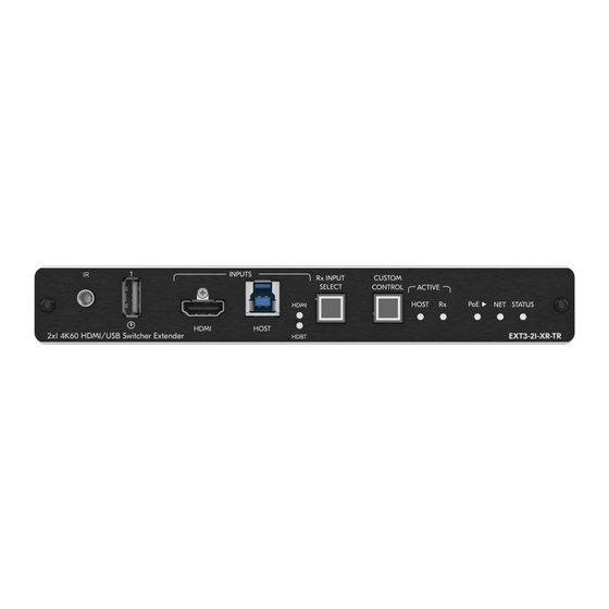
Transmitter or Receiver side. (see Setting Extender Operation Modes on page 31). Figure 1: EXT3-21-XR-TR HDMI & USB 2X1 Switcher Extender Front Panel Feature Function IR 3.5mm Mini Jack Connector Connect to an external IR emitter to control a local IR-controlled device from the remote extender (for example, EXT3-21-XR-TR). - Page 8 Off (Dark) Device is powered and no active source connected. Blue Device is powered, and an active source is connected. Green Device is powered, an active source and acceptor are connected. EXT3-21-XR-TR – Defining EXT3-21-XR-TR HDMI & USB 2X1 Switcher Extender...
- Page 9 Kramer Electronics Ltd. Figure 2: EXT3-21-XR-TR HDMI & USB 2X1 Switcher ExtenderRear Panel Feature Function HDBT PoE RJ-45 Connector Connect to the HDBT RJ-45 connector on a paired receiver/transmitter device (for example, a second EXT3-21-XR-TR device) that receives or provides PoE.
-
Page 10: Mounting Ext3-21-Xr-Tr
Kramer Electronics Ltd. Mounting EXT3-21-XR-TR This section provides instructions for mounting EXT3-21-XR-TR. Before installing, verify that the environment is within the recommended range: • Operation temperature – 0 to 40C (32 to 104F). • Storage temperature – -40 to +70C (-40 to +158F). -
Page 11: Connecting Ext3-21-Xr-Tr
Kramer Electronics Ltd. Connecting EXT3-21-XR-TR Always switch off the power to each device before connecting it to your EXT3-21-XR-TR. After connecting your EXT3-21-XR-TR, connect its power and then switch on the power to each device. Figure 3: Connecting to the EXT3-21-XR-TR Rear Panels... - Page 12 Send serial commands from LAN-connected SL-240C controller to the camera via extender control gateway. 8. Connect the EXT3-21-XR-TR to power source(s), as follows: ▪ Switch up the PoE power selector to LAN position and connect the 1G LAN PoE port to a PoE-providing LAN switch.
-
Page 13: Connecting To Ext3-21-Xr-Tr Via Rs-232
Kramer Electronics Ltd. Connecting to EXT3-21-XR-TR via RS-232 You can connect to EXT3-21-XR-TR via an RS-232 connection using, for example, a PTZ camera, PC, or display. EXT3-21-XR-TR features an RS-232 3-pin terminal block connector allowing the RS-232 to control either the EXT3-21-XR-TR or a serially controllable device. -
Page 14: Operating And Controlling Ext3-21-Xr-Tr
Set the inputs switching policy to connected output and room devices to: • Manual – Select an input manually and switching occurs whether input live signals are present or not. • Auto – Auto Switching selection is performed in either Last Connected or Priority policy. EXT3-21-XR-TR – Operating and Controlling EXT3-21-XR-TR... - Page 15 Kramer Electronics Ltd. In Last Connected policy, if the signal on the current input is lost, EXT3-21-XR-TR automatically selects the last connected input. The auto-switching delay depends on the configurable signal-lost timeout. In Priority policy, when the input sync signal is lost for any reason, the input host with a live signal and next in priority is selected automatically.
-
Page 16: Using Front And Rear Panel Buttons
EXT3-21-XR-TR Flexible Powering EXT3-21-XR-TR, when connected to the power supply, can supply power to the connected transmitter / receiver via HDBT. The EXT3-21-XR-TR, can also accept power from either LAN or HDBT. Single Device Operates as Either Tx or Rx... - Page 17 The Local Area Connection Properties window for the selected network adapter appears as shown in Figure Figure 4: Local Area Connection Properties Window 4. Highlight either Internet Protocol Version 6 (TCP/IPv6) or Internet Protocol Version 4 (TCP/IPv4) depending on the requirements of your IT system. EXT3-21-XR-TR – Operating and Controlling EXT3-21-XR-TR...
- Page 18 Figure 5: Internet Protocol Version 4 Properties Window Figure 6: Internet Protocol Version 6 Properties Window 6. Select Use the following IP Address for static IP addressing and fill in the details as shown in Figure EXT3-21-XR-TR – Operating and Controlling EXT3-21-XR-TR...
- Page 19 When no DHCP server is detected, a fallback static IP address of 192.168.1.39, and 255.255.255.0 subnet mask (class C), is assigned until an IP address is acquired via the DHCP server. For more information, refer to Product Page Technical Note in www.kramerav.com/product/EXT3-21-XR-TR. EXT3-21-XR-TR – Operating and Controlling EXT3-21-XR-TR...
-
Page 20: Using Embedded Web Pages
Kramer Electronics Ltd. Using Embedded Web Pages EXT3-21-XR-TR enables you to configure settings via Ethernet using built-in, user-friendly web pages. The Web pages are accessed using a Web browser and an Ethernet connection. You can also configure EXT3-21-XR-TR via Protocol 3000 commands (see... - Page 21 Kramer Electronics Ltd. 2. Enter the Username (default = Admin) and Password (default = Admin) and click Sign in. The default web page appears. Figure 9: Default Landing Page EXT3-21-XR-TR – Using Embedded Web Pages...
- Page 22 4. Click the Navigation Pane on the left side of the screen to access the relevant web page. Using the embedded webpage, the EXT3-21-XR-TR can be easily set to operate either as a transmitter (Tx) or receiver (Rx). (see Setting Extender Operation Modes on page 31).
-
Page 23: Routing Operations
USB local devices are always connected to active Host. Remote USB devices connections to local active Host is configurable (see Figure 12 & (Figure 13). Active Host connects to all local and remote devices. EXT3-21-XR-TR – Using Embedded Web Pages... - Page 24 Whether in Tx or Rx mode, selecting the correct button in the embedded webpage determines if your local or remote host is active. USB standard compliance allows only a single active USB host (local or remote). EXT3-21-XR-TR – Using Embedded Web Pages...
- Page 25 Figure 13: Selecting Local Active Host for Connection to both Local and Remote USB Devices Depending on USB active host configuration, you control local and remote USB devices via active local host. EXT3-21-XR-TR – Using Embedded Web Pages...
- Page 26 AV signal on input 1 and the USB signal on input 2. This means that the HDMI input 2 AV signal is routed to the AV output and the USB devices are associated with the remote HDBT USB host. Figure 15: Independent routing of USB Host and AV Signal EXT3-21-XR-TR – Using Embedded Web Pages...
-
Page 27: Setting Av Properties
2. Next to the Selection Mode drop-down box, select the auto switching policy: Manual, Last Connected or Priority. AV auto-switching policy is set. To change AV Host Input Priorities: 1. Go to the Auto switching tab. 2. Next to the Selection Mode drop-down box, select Priority. EXT3-21-XR-TR – Using Embedded Web Pages... - Page 28 AV properties related to HDCP and CEC signals are not configurable. They are passing through: • Transmitter-side: Between HDMI input and HDBT output. • Receiver-side: Between HDMI or HDBT input and HDMI output. EXT3-21-XR-TR – Using Embedded Web Pages...
- Page 29 Audio and video settings are configured. Managing EDID EXT3-21-XR-TR enables you to copy an EDID from one of several different sources to the inputs. To copy the EDID to the inputs: 1. Go to the EDID Management page. EXT3-21-XR-TR – Using Embedded Web Pages...
-
Page 30: Device Settings And Maintenance
3. Under Step 2, select one or more inputs as the destination for copying the EDID. 4. Click COPY EDID. The EDID is copied. Device Settings and Maintenance This section details the following actions: • Device Profile and Maintenance on page 30. • Settings Networking Properties on page 34. EXT3-21-XR-TR – Using Embedded Web Pages... - Page 31 Kramer Electronics Ltd. Figure 20: Updated Mode The extender device operation mode was selected and implemented. EXT3-21-XR-TR – Using Embedded Web Pages...
- Page 32 To change the device name: 1. Go to the Device > General page. Figure 21: Device > General Tab 2. Under General Preferences, change the device name and click SAVE. The device name is changed. EXT3-21-XR-TR – Using Embedded Web Pages...
- Page 33 Figure 23: Device Reset Warning Message 4. Click CONTINUE. The extender device is switching operation modes. This can take up to 60 seconds. 5. The extender device mode indication, at the top bar, shows the newly selected mode. EXT3-21-XR-TR – Using Embedded Web Pages...
- Page 34 The stored file can then be imported to the same or different EXT3-21-XR-TR device to load the recorded settings, for configuration backup and/or solution-replication purposes. EXT3-21-XR-TR – Using Embedded Web Pages...
- Page 35 To identify the device using a supporting discovery system: 1. Go to the Device > General page (Figure 21). 2. Under Global System Settings, click FLAG ME. NET LED flashes. The device is identified by the discovery system. EXT3-21-XR-TR – Using Embedded Web Pages...
- Page 36 If required, Set to DHCP (default) or static IP address resolution modes. 4. When in Static IP mode, perform the following actions: ▪ Change the IP address. ▪ Change the Mask address. ▪ Change the Gateway address. 5. Click SAVE. Network settings are defined. EXT3-21-XR-TR – Using Embedded Web Pages...
- Page 37 3. For each USB Device Port, set the auto disconnection status to On or Off. You can also Select All Off or All On to set all device ports to off or on, respectively. 4. Click SAVE. USB devices are set. EXT3-21-XR-TR – Using Embedded Web Pages...
- Page 38 6. If enabled, type in server information: ▪ Enter the time server address. ▪ Set sync frequency (every 0 to 23 days). 7. Click SAVE for any change. The devices date and time are synchronized to the server address entered. EXT3-21-XR-TR – Using Embedded Web Pages...
-
Page 39: Setting Control Gateway Properties
Extender management and control – Device service and control using P3000 commands (serial port 1 only) EXT3-21-XR-TR enables configuring the RS-232 port in one of the following ways: • Extending the RS-232 via the EXT3-21-XR-TR on page 37. • Controlling an External Device on page 40. - Page 40 EXT3-21-XR-TR is set to operate as an RS-232 extender, with end-to-end extension between RS-232 panel port and HDBT RS-232 channel. In extension mode, no configuration of port properties and functions are available (Figure 29). EXT3-21-XR-TR – Using Embedded Web Pages...
- Page 41 1. Go to the Control Gateway page. The Serial Ports tab appears. Figure 30: RS-232 Device Control 2. Select Serial Port 1 3. Next to Tunneling, select Control. 4. Click SAVE. RS-232 port controls the EXT3-21-XR-TR. EXT3-21-XR-TR – Using Embedded Web Pages...
- Page 42 The TUNNELING ADVANCED PROPERTIES settings tab appears. Figure 32: Setting Advanced Tunneling Properties 5. Select either TCP or UDP port. 6. Click up/down arrows to select IP Port. 7. Click up/down arrows to select desired seconds for TCP Keep alive. EXT3-21-XR-TR – Using Embedded Web Pages...
- Page 43 Defining and Testing Commands via Action Editor on page 46) and associate DISPLAY ON/OFF (Custom Control) commands via (see Associating Commands to DISPLAY ON/OFF (Custom control) on page 48). RS-232 port controls the display on/off. EXT3-21-XR-TR – Using Embedded Web Pages...
- Page 44 I/O port. It detects High (upon passing Max threshold from Low state) or Low (upon passing Min threshold from High state) port states according to the user defined voltage threshold levels. EXT3-21-XR-TR – Using Embedded Web Pages...
- Page 45 To configure a digital output I/O type: 1. On the GPIO page, select Digital Output next to I/O type. A warning message appears. Figure 35: Digital Output Warning 2. Make sure to follow the instructions in this warning. EXT3-21-XR-TR – Using Embedded Web Pages...
- Page 46 When the pull-up resistor is disabled, the port state is low. For the state to be high, select High for the Current Status. Make sure that the current in this configuration does not exceed 100mA. 5. Click SAVE. Digital Output I/O type is configured. EXT3-21-XR-TR – Using Embedded Web Pages...
- Page 47 This value is the number of steps that the analog input signal is divided into. To calculate the voltage of each step, use the following formula: Voltage of one step = 30V / number of steps. 3. Click SAVE. Analog input I/O type is configured. EXT3-21-XR-TR – Using Embedded Web Pages...
- Page 48 However, above is a common example of a standard command to power on a TV. ▪ For RS232 – PON ▪ For RELAY - <RelayNum>, <RelayState> ▪ For IR - 1,1,TVON,1,1,1,0000,006f,0022,0002,014d,00a6,0015,0015,0014,0015,0013,0014,00 15,0015,0014,0014,0014,0014,0015,0015,0014,003e,0016,003d,0014,003f,0014,003 e,0015,003f,0013,003f,0014,003e,0015,003f,0013,0016,0013,0015,0014,0015,0013,0 016,0013,003f,0013,003e,0015,0015,0013,003e,0015,003f,0013,003f,0013,003e,001 5,003e,0015,0015,0014,0015,0013,003f,0014,0015,0013,0014,0015,05c9,014d,0053, 0015,0e0a EXT3-21-XR-TR – Using Embedded Web Pages...
- Page 49 Relays, using the Relay tab to open or close a relay, configured as digital outputs on either controllers and auxiliary devices or control gateways. To set a Relay action: 1. In the navigation pane, select Control Gateway. EXT3-21-XR-TR – Using Embedded Web Pages...
- Page 50 • For Tx: HDMI input CEC pass-thru over HDBT output. • For Rx: HDMI/HDBT input CEC pass-thru to HDMI output. To add an action: 1. In the navigation pane, select Control Gateway. The Serial Ports tab opens. EXT3-21-XR-TR – Using Embedded Web Pages...
- Page 51 3. Define the State On and State Off commands. 4. Check Momentary for the button to an ON command on the press of a button, and OFF on button release. 5. Click SAVE. DISPLAY ON button is configured. EXT3-21-XR-TR – Using Embedded Web Pages...
- Page 52 1. In the navigation pane, select Control Gateway. 2. Select the IR tab. The IR tab opens (see Figure 42). 3. Select Tx and Rx IR routing cross-points by clicking on their IR icons. Selected IR routing indication appears. EXT3-21-XR-TR – Using Embedded Web Pages...
- Page 53 Figure 42: IR Tab Signals Routing Figure 43: IR Modulation Method Setting Setting Audio Output Volume Level To set the audio output volume level, (see Setting Analog Audio Output Volume Level on page 25). EXT3-21-XR-TR – Using Embedded Web Pages...
-
Page 54: Diagnostics
To view the device status: 1. In the navigation pane, select Status. 2. Select the Devices tab. The Devices Status appears. Figure 44: Device Status Page 3. View device status. Device status can be viewed. EXT3-21-XR-TR – Using Embedded Web Pages... -
Page 55: Administration
Setting Security Status to Off To set security status to Off: 1. Go to the Security page (Figure 45). 2. Select the Security tab. The Security settings appear. Figure 45: Security – Security Tab EXT3-21-XR-TR – Using Embedded Web Pages... - Page 56 3. Enter the Current Password and click Change. The new password settings appear. Figure 47: Device Settings – Changing the Password 4. Enter the new password and confirmation password and click SAVE. The password is changed. EXT3-21-XR-TR – Using Embedded Web Pages...
- Page 57 2. Select 802.1X tab. The 802.1X settings tab appears (see Figure 48). Figure 48: 802.1X Tab 3. For 802.1x authentication, click ON to enable 802.1x authentication service. 802.1x supports authentication based on port and MAC address. EXT3-21-XR-TR – Using Embedded Web Pages...
- Page 58 PEAP-MSCHAP V2 (Figure 49) – Enter: Username - up to 24 alphanumeric characters, including “_” and “-“ characters within the username, and Password - up to 24 ASCII characters Figure 50: Security Tab – EAP-MSCHAP V2 Authentication EXT3-21-XR-TR – Using Embedded Web Pages...
- Page 59 ▪ Enter the private key password (assigned by IT administrator), ▪ Set Server Certificate On Figure 52: EAP-TLS – Certificates and Password 5. Click APPLY. 802.1x authentication security is configured. EXT3-21-XR-TR – Using Embedded Web Pages...
-
Page 60: Viewing The About Page
Kramer Electronics Ltd. Viewing the About Page View the firmware version and Kramer Electronics Ltd details in the About page. Figure 53: About Page EXT3-21-XR-TR – Using Embedded Web Pages... -
Page 61: Upgrading Firmware
The latest version of K-UPLOAD and installation instructions can be downloaded from our website at: www.kramerav.com/support/product_downloads.asp. Note that in order to use the micro USB port, you need to install the Kramer USB driver, available at: www.kramerav.com/support/product_downloads.asp. EXT3-21-XR-TR – Upgrading Firmware... -
Page 62: Technical Specifications
2 GPIO On a 2–pin terminal block connector 2 Relay On a 4–pin terminal block connector Extension Line Reach Up to 100m (330ft), using Kramer HDBaseT cables Standards Compliance HDBaseT 3.0 Video Max Data Rate 18Gbps bandwidth (6Gbps per graphic... - Page 63 0.60 kg (1.32 lbs) Shipping Weight 1.11 kg (2.44 lbs) Accessories Included Power Adapter & cord & Bracket set & QS Product Warranty Contact Customer Support Period Specifications are subject to change without notice at www.kramerav.com EXT3-21-XR-TR – Technical Specifications...
-
Page 64: Default Communication Parameters
Full Factory Reset “#FACTORY” command. "FACTORY OK” After receiving perform one of the following to restart the device and complete the procedure • Power cycle • Send command "#RESET" Embedded webpages Go to: Device>General and click FACTORY RESET EXT3-21-XR-TR – Technical Specifications... -
Page 65: Protocol 3000
Kramer Electronics Ltd. Protocol 3000 Kramer devices can be operated using Kramer Protocol 3000 commands sent via serial or Ethernet ports. Understanding Protocol 3000 Protocol 3000 commands are a sequence of ASCII letters, structured according to the following. • Command format:... -
Page 66: Protocol 3000 Commands
TCP – UDP control port udp_port ~nn@BEACON- control port, MAC – TCP control port tcp_port INFOport_id, ip_string,udp_port,tcp_port,mac_address, address, model, name. – Dash-separated mac mac_address model,name<CR><LF> address model – Device model – Device name name EXT3-21-XR-TR – Protocol 3000... - Page 67 Clear CEC messages. COMMAND Clear all CEC messages: – Type of Sub_category_clr #COUNTER-CLR?category_id,sub_category_clr<CR> #COUNTER-CLR?0,*<CR> message to clear: FEEDBACK 0 – Clear sent messages ~nn@COUNTER- 1 – Clear received messages CLRcategory_id,sub_category_id,count<CR><LF> * – Clear all CEC messages EXT3-21-XR-TR – Protocol 3000...
- Page 68 – Audio block added to audio_format EDID: 0 – Auto 1 – LPCM 2CH 2 – LPCM 6CH 3 – LPCM 8CH 4 – Bitstream 5 – HD EXT3-21-XR-TR – Protocol 3000...
- Page 69 #ETH-PORT?port_type<CR> port_id protocol for UDP: (0 – 65535) #ETH-PORT?UDP<CR> FEEDBACK If the port number ~nn@ETH-PORTport_type,port_id<CR><LF> you enter is already in use, an error is returned. The port number must be within the following range: 0-(2^16-1). EXT3-21-XR-TR – Protocol 3000...
- Page 70 The device uses this command to notify the user of any change regarding the step and voltage in: In digital mode the answer is 0 (low), 1 (high). In analog mode the answer is 0 to 100. EXT3-21-XR-TR – Protocol 3000...
- Page 71 HDCP supported – 1 – HDCP On HDCP ON [default]. 2 – Follow Input HDCP not supported - 3 – HDCP defined according to the HDCP OFF. connected output HDCP support changes following detected sink - MIRROR OUTPUT. EXT3-21-XR-TR – Protocol 3000...
- Page 72 – IR Status ir_status 0 – Sent (no error) 1 – Stop 2 – Done 3 – Busy 4 – Wrong Parameter 5 – Nothing to Stop 6 – Start 7 – Timeout 8 – Error EXT3-21-XR-TR – Protocol 3000...
- Page 73 Get EDID Lock status. COMMAND Get input 2 Lock EDID #LOCK-EDID?in_index <CR> status: specific input: 1 – USB-C IN #LOCK-EDID?2<CR> FEEDBACK 2 – HDMI IN ~nn@LOCK-EDIDin_index,lock_mode<CR><LF> – On/Off lock_mode 0 – Off unlocks EDID 1 – On locks EDID EXT3-21-XR-TR – Protocol 3000...
- Page 74 #NAMEroom-442<CR> FEEDBACK The machine name ~nn@NAMEmachine_name<CR><LF> is not the same as the model name. The machine name is used to identify a specific machine or a network in use (with DNS feature on). EXT3-21-XR-TR – Protocol 3000...
- Page 75 – Format: xxx.xxx.xxx.xxx NET-GATE? Get gateway IP. COMMAND Get the gateway IP address: A network gateway #NET-GATE?<CR> #NET-GATE?<CR> connects the device FEEDBACK via another network ~nn@NET-GATEip_address<CR><LF> and maybe over the Internet. Be aware of security problems. EXT3-21-XR-TR – Protocol 3000...
- Page 76 #PRG- command. #PRG-ACTION?commandNum<CR> ACTION?0,3,1,0<CR> 1 – Output FEEDBACK Programs matrix – External programmable button type ~nn@PRG-ACTIONcommandNum,type,name,command<CR><LF> action as a response for external event – Bitmap representing name (programmable button – External programmable command pressed). button ID EXT3-21-XR-TR – Protocol 3000...
- Page 77 Set the priority to first HDMI 1 – Video 2, USB-C 1 second and #PRIORITYlayer_type,priority_1,priority_2,priority_3 HDMI 3 third: <CR> – Priority of inputs (1-2) priority #PRIORITY1,2,1,3<CR> 1 – USB-C 1 FEEDBACK 2 – HDMI 2 ~nn@PRIORITYlayer_type,priority_1,priority_2,priorit 3 – HDMI 3 y_3<CR><LF> EXT3-21-XR-TR – Protocol 3000...
- Page 78 The device does not – Format: hh:mm:ss where data validate the day of hh = hours week from the date. mm = minutes ss = seconds Time format - 24 hours. Date format - Day, Month, Year. EXT3-21-XR-TR – Protocol 3000...
- Page 79 0 – disable meaning that if the 1 – enable extra parameters do not exist, FW goes to. (optional - this exists only when serial_type is 485) RS-232. Stop_bits 1.5 is only relevant for 5 data_bits. EXT3-21-XR-TR – Protocol 3000...
-
Page 80: Result And Error Codes
In case of an error, the device responds with an error message. The error message syntax: • ~NN@ERR XXX<CR><LF> – when general error, no specific command • ~NN@CMD ERR XXX<CR><LF> – for specific command • NN – machine number of device, default = 01 • XXX – error code EXT3-21-XR-TR – Protocol 3000... - Page 81 (Reserved) ERR_RESERVED_8 (Reserved) ERR_RESERVED_9 (Reserved) ERR_RESERVED_10 (Reserved) ERR_RESERVED_11 (Reserved) ERR_RESERVED_12 (Reserved) ERR_EDID_CORRUPTED EDID corrupted ERR_NON_LISTED Device specific errors File has the same CRC – not changed ERR_SAME_CRC ERR_WRONG_MODE Wrong operation mode ERR_NOT_CONFIGURED Device/chip was not initialized EXT3-21-XR-TR – Protocol 3000...
- Page 82 This limited warranty gives you specific legal rights, and you may have other rights which vary from country to country or state to state. This limited warranty is void if (i) the label bearing the serial number of this product has been removed or defaced, (ii) the product is not distributed by Kramer Electronics or (iii) this product is not purchased from an authorized Kramer Electronics reseller.
- Page 83 SAFETY WARNING Disconnect the unit from the power supply before opening and servicing For the latest information on our products and a list of Kramer distributors, visit our website where updates to this user manual may be found. We welcome your questions, comments, and feedback.
Need help?
Do you have a question about the EXT3-21-XR-TR and is the answer not in the manual?
Questions and answers