Table of Contents
Advertisement
Quick Links
Advertisement
Chapters
Table of Contents

Related Manuals for Agilent Technologies 1670G Series


Summary of Contents for Agilent Technologies 1670G Series
- Page 1 Service Guide Publication number 01670-97023 November 2003 For Safety information, Warranties, and Regulatory information, see the pages at the end of the book. © Copyright Agilent Technologies 1987–2003 All Rights Reserved. Agilent Technologies 1670G-Series Logic Analyzers...
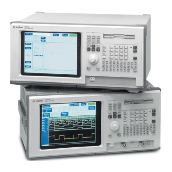
- Page 2 Agilent Technologies 1670G-Series Logic Analyzers The Agilent 1670G-Series are 150-MHz State/500-MHz Timing Logic Analyzers. There are two options available. One option is to add a 2 GSa/s digitizing oscilloscope. Another option is to add a 32 channel pattern generator. Features Some of the main features of the Agilent 1670G-Series Logic Analyzers are as follows: •...
- Page 3 This service guide contains information for finding a defective assembly by testing and servicing the Agilent 1670G-series logic analyzers. This logic analyzer can be returned to Agilent for all service work, including troubleshooting. Contact your nearest Agilent Technologies Sales Office for details. Agilent Technologies 1670G-Series Logic Analyzer...
- Page 4 Chapter 5 contains self-tests and flowcharts for troubleshooting the logic analyzer. Chapter 6 tells how to replace assemblies of the logic analyzer and how to return them to Agilent Technologies. Chapter 7 lists replaceable parts, shows an exploded view, and gives ordering information.
-
Page 5: Table Of Contents
Table of Contents Service Strategy 1–iii 1 General Information Accessories 1–2 Specifications (logic analyzer) 1–3 Specifications (oscilloscope) 1–4 Specifications (pattern generator) 1–4 Characteristics (logic analyzer) 1–5 Characteristics (oscilloscope) 1–5 Characteristics (pattern generator) 1–6 Recommended Test Equipment (logic analyzer) 1–9 Recommended test equipment (oscilloscope) 1–10 Recommended test equipment (pattern generator) 1–11 2 Preparing for Use To inspect the logic analyzer 2–2... - Page 6 Contents Check the setup/hold with single clock edges, multiple clocks 3–36 Test the next channels 3–40 To test the single-clock, multiple-edge, state acquisition (logic analyzer) 3–41 Set up the equipment 3–41 Set up the logic analyzer 3–42 Connect the logic analyzer 3–44 Verify the test signal 3–47 Check the setup/hold with single clock, multiple clock edges 3–49 Test the next channels 3–52...
- Page 7 Contents Acquire the data 3–80 To test the trigger sensitivity (oscilloscope) 3–81 Set up the equipment 3–81 Set up the logic analyzer 3–82 Connect the logic analyzer 3–84 Acquire the data 3–84 Performance Test Record (logic analyzer) 3–85 Performance Test Record (oscilloscope) 3–88 Performance Test Record (pattern generator) 3–91 4 Calibrating and Adjusting Logic analyzer calibration 4–2...
- Page 8 Contents To remove and replace the disk drive assembly 6–6 To remove and replace the acquisition board 6–7 To remove and replace the CPU board 6–9 To remove and replace SIMM memory 6–10 To remove and replace the rear panel 6–11 To remove and replace the power supply 6–12 To remove and replace the oscilloscope board (oscilloscope option only) 6–13 To remove and replace pattern generator board ( pattern generator option only) 6–14...
-
Page 9: General Information
Accessories 1–2 Specifications (logic analyzer) 1–3 Specifications (oscilloscope) 1–4 Specifications (pattern generator) 1–4 Characteristics (logic analyzer) 1–5 Characteristics (oscilloscope) 1–5 Characteristics (pattern generator) 1–6 Recommended Test Equipment (logic analyzer) 1–9 Recommended Test Equipment (oscilloscope) 1–10 Recommended Test Equipment (pattern generator) 1–11 General Information... -
Page 10: Accessories
General Information This chapter lists the accessories, the specifications and characteristics, and the recommended test equipment. Accessories The following accessories are supplied with the Agilent 1670G-series logic analyzers. The part numbers are current as of the print date of this edition of the Service Guide, but further upgrades may change the part numbers. -
Page 11: Specifications (Logic Analyzer)
General Information Specifications (logic analyzer) Specifications (logic analyzer) The specifications are the performance standards against which the product is tested. Maximum State Speed (selectable) 150 MHz Minimum Master to Master Clock Time 6.666 ns ± (100 mV + 3% of threshold setting) Threshold Accuracy Setup/Hold Time: Single Clock, Single Edge... -
Page 12: Specifications (Oscilloscope)
General Information Specifications (oscilloscope) Specifications (oscilloscope) The Agilent 1670G Logic Analyzers with an oscilloscope also include the following specifications: (*,1) Bandwidth DC to 500 MHz (real time, dc-coupled) (*, 2) ±[(0.005% X ∆t)+ Time Interval Measurement Accuracy −6 (2 x 10 x delay setting)+150 ps] ±(1.0% of channel offset + 2.0% of full scale) DC Offset Accuracy... -
Page 13: Characteristics (Logic Analyzer)
General Information Characteristics (logic analyzer) Characteristics (logic analyzer) These characteristics are not specifications, but are included as additional information. Full Channel Half Channel Maximum State Clock Rate 150 MHz not applicable Maximum Conventional Timing Rate 250 MHz 500 MHz Memory Depth 128K Memory Depth (option #001) 256K... -
Page 14: Characteristics (Pattern Generator)
General Information Characteristics (pattern generator) Characteristics (pattern generator) The Agilent 1670G Logic Analyzers with a pattern generator also include the following characteristics: Output channels 16 channels at 200 MHz clock; 32 channels at 100 MHz clock Memory depth 258,048 vectors Logic levels (data pods) TTL, 3-state TTL/3.3v, 3-state TTL/CMOS, ECL terminated, ECL unterminated, and differential... - Page 15 General Information Characteristics (pattern generator) Probes Maximum Input Voltage + 40V, CAT 1 Auxiliary Power Power Through Cables 1/3 amp at 5 V maximum per cable, CAT 1 Operating Environment (for indoor use only) Instrument, 0 °C to 55 °C (+32 °F to 131 °F). Temperature Probe lead sets and cables, 0 °C to 65 °C (+32 °F to 149 °F).
- Page 16 General Information Characteristics (pattern generator) Product Regulations Safety IEC 1010-1:1990+A1 / EN 61010-1:1993 UL3111 CSA-C22.2 No. 1010.1:1993 This product meets the requirement of the European Communities (EC) EMC Directive 89/336/EEC. Emissions EN55011/CSIPR 11 (ISM, Group1,Class A equipment) IEC 555-2 and IEC 555-3 Immunity EN50082-1 Code...
-
Page 17: Recommended Test Equipment (Logic Analyzer)
General Information Recommended Test Equipment (logic analyzer) Recommended Test Equipment (logic analyzer) Equipment Required Equipment Critical Specifications Recommended Model/Part Pulse Generator 150 MHz, 3.0 ns pulse width, 8133A Option 003 < 600 ps rise time ≥ 6 GHz bandwidth, < 58 ps rise time Digitizing Oscilloscope 54750A mainframe with 54751A plugin module... -
Page 18: Recommended Test Equipment (Oscilloscope)
General Information Recommended test equipment (oscilloscope) Recommended test equipment (oscilloscope) Equipment Required Equipment Critical Specifications Recommended Use* Model/Part Signal Generator Frequency: 1 - 500 MHz at approx. 8656B Option 001 170 mV RMS Output Accuracy: ± 1 dB 1 MHz time base accuracy 0.25 ppm Range: −35.000 to +35.000 Vdc, ±1 mV DC Power Supply 3245A Option 002... -
Page 19: Recommended Test Equipment (Pattern Generator)
General Information Recommended test equipment (pattern generator) Recommended test equipment (pattern generator) Equipment Required Equipment Critical Specifications Recommended Use* Model/Part ≥ 500 MHz Bandwidth Oscilloscope 54820A Probe 500 MHz Bandwidth 1160A Output Data Pod no substitute 10460A - series * T = Troubleshooting 1–11... - Page 20 1–12...
-
Page 21: Preparing For Use
To inspect the logic analyzer 2–2 To apply power 2–3 To operate the user interface 2–3 To clean the logic analyzer 2–3 To test the logic analyzer 2–4 Preparing for Use... -
Page 22: To Inspect The Logic Analyzer
Inspect the product for physical damage. Check the logic analyzer and the supplied accessories for obvious physical or mechanical defects. If you find any defects, contact your nearest Agilent Technologies Sales Office. Arrangements for repair or replacement are made, at Agilent Technologies’ option, without waiting for a claim settlement. -
Page 23: To Apply Power
Preparing for Use To apply power To apply power Check that the line voltage selector, located on the rear panel, is on the correct setting and the correct fuse is installed. See also, "To set the line voltage" on this page. Connect the power cord to the instrument and to the power source. -
Page 24: To Test The Logic Analyzer
Preparing for Use To test the logic analyzer To test the logic analyzer • If you require a test to verify the specifications, start at the beginning of chapter 3, "Testing Performance." • If you require a test to initially accept the operation, perform the self-tests in chapter 3. -
Page 25: Testing Performance
To perform the self-tests 3-3 To make the test connectors (logic analyzer) 3-7 To test the threshold accuracy (logic analyzer) 3-9 To test the single-clock, single-edge, state acquisition (logic analyzer) 3-17 To test the multiple-clock, multiple-edge, state acquisition (logic analyzer) 3-29 To test the single-clock, multiple-edge, state acquisition (logic analyzer) 3-41 To test the time interval accuracy (logic analyzer) 3-53 To test the CAL OUTPUT ports (oscilloscope) 3-59... - Page 26 Testing Performance This chapter tells you how to test the performance of the logic analyzer against the specifications listed in chapter 1. To ensure the logic analyzer is operating as specified, you perform software tests (self-tests) and manual performance tests on the analyzer.
-
Page 27: To Perform The Self-Tests
To perform the self-tests The self-tests verify the correct operation of the logic analyzer. Self-tests can be performed all at once or one at a time. While testing the performance of the logic analyzer, run the self-tests all at once. The performance verification (PV) self-tests consist of system PV tests and analyzer PV tests. - Page 28 Testing Performance To perform the self-tests Install a formatted disk that is not write protected into the disk drive. Connect an RS-232-C loopback connector onto the RS-232-C port. Select All System Tests. You can run all tests at one time, except for the Front Panel Test and Display Test, by running All System Tests.
- Page 29 Testing Performance To perform the self-tests Select Sys PV, then select Analy PV in the pop-up menu. In the Analy PV menu, select Board Verification. In the Board Verification menu, select All Tests. You can run all tests at one time by selecting All Tests. To see more details about each test when troubleshooting failures, you can run each test individually.
- Page 30 Testing Performance To perform the self-tests Select Exit to exit the Board Verification. In the Analy PV menu, select Acquisition IC Verification. In the Acquisition IC Verification menu, select All Tests. When the tests finish, the status for each test shows PASSED or FAILED, and the status for the All Tests changes from UNTESTED to TESTED.
-
Page 31: To Make The Test Connectors (Logic Analyzer)
To make the test connectors (logic analyzer) The test connectors connect the logic analyzer to the test equipment. Materials Required Description Recommended Part BNC (f) Connector 1250-1032 100 Ω 1% resistor 0698-7212 Berg Strip, 17-by-2 Berg Strip, 6-by-2 20:1 Probe 54006A Jumper wire Build four test connectors using BNC connectors and 6-by-2 sections of Berg strip. - Page 32 Testing Performance To make the test connectors (logic analyzer) Build one test connector using a BNC connector and a 17-by-2 section of Berg strip. a Solder a jumper wire to all pins on one side of the Berg strip. b Solder a jumper wire to all pins on the other side of the Berg strip. c Solder the center of the BNC connector to the center pin of one row on the Berg strip.
-
Page 33: To Test The Threshold Accuracy (Logic Analyzer)
To test the threshold accuracy (logic analyzer) Testing the threshold accuracy verifies the performance of the following specification: • Clock and data channel threshold accuracy. These instructions include detailed steps for testing the threshold settings of pod 1. After testing pod 1, connect and test the rest of the pods one at a time. To test the next pod, follow the detailed steps for pod 1, substituting the next pod for pod 1 in the instructions. -
Page 34: Set Up The Logic Analyzer
Testing Performance To test the threshold accuracy (logic analyzer) Set up the logic analyzer Press the Config key. Unassign Pods 3 and 4, Pods 5 and 6, and Pods 7 and 8. To unassign the pods, select the pod field. In the pop-up menu, select Unassigned. Set up the Format menu. - Page 35 Testing Performance To test the threshold accuracy (logic analyzer) Set up the Waveform menu. a Press the Waveform key. b In the Waveform menu, move the cursor to the pod/channel selection field, then press Select. In the pop-up menu, select Delete All, then select Continue. c Again press Select.
-
Page 36: Connect The Logic Analyzer
Testing Performance To test the threshold accuracy (logic analyzer) Connect the logic analyzer Using the 17-by-2 test connector, BNC cable, and probe tip assembly, connect the data and clock channels of pod 1 to one side of the BNC Tee. Using a BNC-banana cable, connect the voltmeter to the other side of the BNC Tee. -
Page 37: Test The Ecl Threshold
Testing Performance To test the threshold accuracy (logic analyzer) Test the ECL Threshold Set up the Format menu. a Press the Format key. b Select the field to the right of Pod A1, then select ECL in the pop-up menu. Test the high-to-low transition. - Page 38 Testing Performance To test the threshold accuracy (logic analyzer) Test the low-to-high transition a On the DC source, enter -1.162 V b On the logic analyzer, press Run. The display should show all channels at a logic "1". Record a PASS/FAIL in the performance test record for Threshold Accuracy Pod 1 - ECL.
-
Page 39: Test The 0 V User Threshold
Testing Performance To test the threshold accuracy (logic analyzer) Test the 0 V User threshold Set up the Format menu. a Press the Format key. b Select the field to the right of Pod A1, then select User in the pop-up menu, then enter 0 V. -
Page 40: Test The Next Pod
Testing Performance To test the threshold accuracy (logic analyzer) Test the next pod Using the 17-by-2 test connector and probe tip assembly, connect the data and clock channels of the next pod to the output of the function generator until all pods have been tested. -
Page 41: To Test The Single-Clock, Single-Edge, State Acquisition (Logic Analyzer)
To test the single-clock, single-edge, state acquisition (logic analyzer) Testing the single-clock, single-edge, state acquisition verifies the performance of the following specifications: • Minimum master-to-master clock time • Maximum state acquisition speed • Setup/Hold time for single-clock, single-edge, state acquisition This test checks two combinations of data channels using a single-edge clock at two selected setup/hold times. -
Page 42: Set Up The Logic Analyzer
Testing Performance To test the single-clock, single-edge, state acquisition (logic analyzer) Set up the oscilloscope. a Select Setup, then select Default Setup. b Configure the oscilloscope according to the following table. Oscilloscope Setup Acquisition Display Trigger [Shift] ∆ Time Averaging: On Graticule Level: -250 mV Stop src: channel 2 [Enter]... - Page 43 Testing Performance To test the single-clock, single-edge, state acquisition (logic analyzer) Set up the Format menu. a Press the Format key. b Select the field to the right of each pod, then select ECL in the pop-up menu. Use the knob to access pods not shown on the screen.
-
Page 44: Connect The Logic Analyzer
Testing Performance To test the single-clock, single-edge, state acquisition (logic analyzer) Connect the logic analyzer Using the 6-by-2 test connectors, connect the first combination of logic analyzer clock and data channels listed in one of the following tables to the pulse generator. If you are testing an Agilent 1670G or Agilent 1671G, you will repeat this test for the second combination. - Page 45 Testing Performance To test the single-clock, single-edge, state acquisition (logic analyzer) Connect the Agilent 1672G or Agilent 1673G Logic Analyzer to the Pulse Generator Testing Connect to Connect to Connect to Combination 8133A 8133A Channel 2 8133A Channel 1 Channel 2 Output Output Output Pod 1, channel 3...
- Page 46 Testing Performance To test the single-clock, single-edge, state acquisition (logic analyzer) Configure the trigger according to the connected channels. a Press the Trigger key. b Select the field next to "a" under the label Bus1. Type the following for your logic analyzer, then press the Select key.
-
Page 47: Verify The Test Signal
Testing Performance To test the single-clock, single-edge, state acquisition (logic analyzer) Verify the test signal Check the clock period. Using the oscilloscope, verify that the master-to-master clock time is 6.666 ns, +0 ps or −100 ps. a In the oscilloscope Timebase menu, select Scale: 1.000 ns/div. b In the oscilloscope Timebase menu, select Position. -
Page 48: Check The Setup/Hold Combination
Testing Performance To test the single-clock, single-edge, state acquisition (logic analyzer) Check the setup/hold combination Select the logic analyzer setup/hold time. a In the logic analyzer Format menu, select Master Clock. b Select the Setup/Hold field, then select the setup/hold combination to be tested for all pods. - Page 49 Testing Performance To test the single-clock, single-edge, state acquisition (logic analyzer) c On the oscilloscope, select [Shift] ∆ Time, then select [Enter] to display the setup time (∆ Time(1)-(2)). d Adjust the pulse generator channel 1 Delay until the pulses are aligned according the the setup time of the setup/hold combination selected, +0.0 ps or -100 ps.
- Page 50 Testing Performance To test the single-clock, single-edge, state acquisition (logic analyzer) Note: Do this step only the first time through the test, to create a Compare file. For subsequent runs, go to step 6. Use the following to create a Compare file: a Press Run.
- Page 51 Testing Performance To test the single-clock, single-edge, state acquisition (logic analyzer) c Adjust the pulse generator channel 1 Delay until the pulses are aligned according the the setup time of the setup/hold combination selected, +0.0 ps or -100 ps. Disregard the oscilloscope Period(2) value. The settings provided in this procedure measure the period from rising edge to rising edge, which is not a valid measurement.
-
Page 52: Test The Next Channels
Testing Performance To test the single-clock, single-edge, state acquisition (logic analyzer) Test the next clock. a Press the Format key, then select Master Clock. b Turn off and disconnect the clock just tested. c Repeat steps 10, 11, and 12 for the next clock edge listed in the table in step 11, until all listed clock edges have been tested. -
Page 53: To Test The Multiple-Clock, Multiple-Edge, State Acquisition (Logic Analyzer)
To test the multiple-clock, multiple-edge, state acquisition (logic analyzer) Testing the multiple-clock, multiple-edge, state acquisition verifies the performance of the following specifications: • Minimum master-to-master clock time • Maximum state acquisition speed • Setup/Hold time for multiple-clock, multiple-edge, state acquisition This test checks two combinations of data using multiple clocks at two selected setup/hold times. -
Page 54: Set Up The Logic Analyzer
Testing Performance To test the multiple-clock, multiple-edge, state acquisition (logic analyzer) Set up the oscilloscope. If the oscilloscope was not configured for the previous test, then do the following steps. a Select Setup, then select Default Setup. b Configure the oscilloscope according to the following table. Oscilloscope Setup Acquisition Display... - Page 55 Testing Performance To test the multiple-clock, multiple-edge, state acquisition (logic analyzer) Set up the Format menu. a Press the Format key. b Select the field to the right of each Pod field, then select ECL. The screen does not show all Pod fields at one time. Use the knob to access more Pod fields. Set up the Trigger menu.
-
Page 56: Connect The Logic Analyzer
Testing Performance To test the multiple-clock, multiple-edge, state acquisition (logic analyzer) Connect the logic analyzer Using the 6-by-2 test connectors, connect the first combination of logic analyzer clock and data channels listed in one of the following tables to the pulse generator. If you are testing an Agilent 1670G or Agilent 1671G, you will repeat this test for the second combination. - Page 57 Testing Performance To test the multiple-clock, multiple-edge, state acquisition (logic analyzer) Connect the Agilent 1672G or Agilent 1673G Logic Analyzer to the Pulse Generator Testing Connect to Connect to Connect to Combination 8133A 8133A Channel 2 8133A Channel 1 Channel 2 Output Output Output Pod 1, channel 3...
- Page 58 Testing Performance To test the multiple-clock, multiple-edge, state acquisition (logic analyzer) Configure the trigger according to the connected channels. a. Press the Trigger key. b. Select the field next to the pattern recognizer "a" under the label Bus1. Type the following for your logic analyzer, then press Select.
-
Page 59: Verify The Test Signal
Testing Performance To test the multiple-clock, multiple-edge, state acquisition (logic analyzer) Verify the test signal Check the clock period. Using the oscilloscope, verify that the master-to-master clock time is 6.666 ns, +0 ps or −100 ps. a In the oscilloscope Timebase menu, select Scale: 1.000 ns/div. b In the oscilloscope Timebase menu, select Position. -
Page 60: Check The Setup/Hold With Single Clock Edges, Multiple Clocks
Testing Performance To test the multiple-clock, multiple-edge, state acquisition (logic analyzer) Check the setup/hold with single clock edges, multiple clocks Select the logic analyzer setup/hold time. a In the logic analyzer Format menu, select Master Clock. b Select and activate any two clock edges. c Select the Setup/Hold field and select the setup/hold to be tested for all pods. - Page 61 Testing Performance To test the multiple-clock, multiple-edge, state acquisition (logic analyzer) c On the oscilloscope, select [Shift] ∆ Time, then select [Enter] to display the setup time (∆ Time(1)-(2)). d Adjust the pulse generator channel 1 Delay until the pulses are aligned according the the setup time of the setup/hold combination selected, +0.0 ps or -100 ps.
- Page 62 Testing Performance To test the multiple-clock, multiple-edge, state acquisition (logic analyzer) Note: Do this step if you have not already created a Compare file for the previous test (single-clock, single-edge state acquisition), use the following steps to create one. For subsequent passes through this test, skip this step and go to step 6. Use the following to create a Compare file: a Press Run.
- Page 63 Testing Performance To test the multiple-clock, multiple-edge, state acquisition (logic analyzer) Using the Delay mode of the pulse generator channel 1, position the pulses according to the setup/hold combination selected, +0.0 ps or -100 ps. a On the Oscilloscope, select [Define meas] Define ∆ Time - Stop edge: falling. b On the oscilloscope, select [Shift] ∆...
-
Page 64: Test The Next Channels
Testing Performance To test the multiple-clock, multiple-edge, state acquisition (logic analyzer) Press the blue shift key, then press the Run key. If two to four acquisitions are obtained without the "Stop Condition Satisfied" message appearing, then the test passes. Press Stop to halt the acquisition. Record the Pass or Fail results in the performance test record. -
Page 65: To Test The Single-Clock, Multiple-Edge, State Acquisition (Logic Analyzer)
To test the single-clock, multiple-edge, state acquisition (logic analyzer) Testing the single-clock, multiple-edge, state acquisition verifies the performance of the following specifications: • Minimum master-to-master clock time • Maximum state acquisition speed • Setup/Hold time for single-clock, multiple-edge, state acquisition This test checks two combinations of data using a multiple-edge single clock at two selected setup/hold times. -
Page 66: Set Up The Logic Analyzer
Testing Performance To test the single-clock, multiple-edge, state acquisition (logic analyzer) Set up the oscilloscope. If the oscilloscope was not configured for the previous test, then do the following steps. a Select Setup, then select Default Setup. b Configure the oscilloscope according to the following table. Oscilloscope Setup [Shift] ∆... - Page 67 Testing Performance To test the single-clock, multiple-edge, state acquisition (logic analyzer) Set up the Format menu. a Press the Format key. b Select the field to the right of each pod field, then select ECL. The screen does not show all pod fields at one time. Use the knob to access pod fields not shown on the screen.
-
Page 68: Connect The Logic Analyzer
Testing Performance To test the single-clock, multiple-edge, state acquisition (logic analyzer) Connect the logic analyzer Using the 6-by-2 test connectors, connect the first combination of logic analyzer clock and data channels listed in one of the following tables to the pulse generator. If you are testing an Agilent 1670G or Agilent 1671G, you will repeat this test for the second combination. - Page 69 Testing Performance To test the single-clock, multiple-edge, state acquisition (logic analyzer) Connect the Agilent 1672G or 1673G Logic Analyzer to the Pulse Generator Testing Connect to Connect to Connect to Combination 8133A 8133A Channel 2 8133A Channel 1 Channel 2 Output Output Output Pod 1, channel 3...
- Page 70 Testing Performance To test the single-clock, multiple-edge, state acquisition (logic analyzer) Configure the trigger according to the connected channels. a Press the Trigger key. b Select the field next to "a" under the label Bus1. Type the following for your logic analyzer, then press the Select key.
-
Page 71: Verify The Test Signal
Testing Performance To test the single-clock, multiple-edge, state acquisition (logic analyzer) Verify the test signal Check the clock period. Using the oscilloscope, verify that the master-to-master clock time is 6.666 ns, +0 ps or – 100 ps. a Enable the pulse generator channel 1, channel 2, and trigger outputs (LED off). b In the oscilloscope Timebase menu, select Scale: 2.000 ns/div. - Page 72 Testing Performance To test the single-clock, multiple-edge, state acquisition (logic analyzer) Check the data pulse width. Using the oscilloscope, verify that the data pulse width is 3.500 ns, +0 ps or −100 ps. a In the oscilloscope Timebase menu, select Scale: 1.000 ns/div. b In the oscilloscope Timebase menu, select Position.
-
Page 73: Check The Setup/Hold With Single Clock, Multiple Clock Edges
Testing Performance To test the single-clock, multiple-edge, state acquisition (logic analyzer) Check the setup/hold with single clock, multiple clock edges Select the logic analyzer setup/hold time. a In the logic analyzer Format menu, select Master Clock. b Select and activate any multiple clock edge. c Select the Setup/Hold field, then select the setup/hold to be tested for all pods. - Page 74 Testing Performance To test the single-clock, multiple-edge, state acquisition (logic analyzer) Using the Delay mode of the pulse generator channel 2, position the pulses according to the setup time of the setup/hold combination selected, +0.0 ps or −100 ps. a On the Oscilloscope, select [Define meas] Define ∆ Time - Stop edge: rising. b In the oscilloscope timebase menu, select Position.
- Page 75 Testing Performance To test the single-clock, multiple-edge, state acquisition (logic analyzer) Note: Do this step if you have not already created a Compare file for one of the previous tests, use the following steps to create one. For subsequent passes through this test, skip this step and go to step 5.
-
Page 76: Test The Next Channels
Testing Performance To test the single-clock, multiple-edge, state acquisition (logic analyzer) Test the next setup/hold combination. a In the logic analyzer Format menu, select Master Clock. b Turn off and disconnect the clock just tested. c Repeat steps 1 through 10 for the next setup/hold combination listed in step 1 on page 3–48, until all listed setup/hold combinations have been tested. - Page 77 To test the time interval accuracy (logic analyzer) Testing the time interval accuracy does not check a specification, but does check the following: • 125-MHz oscillator This test verifies that the 125-MHz timing acquisition synchronizing oscillator is operating within limits. Equipment Required Equipment Critical Specifications...
-
Page 78: To Test The Time Interval Accuracy (Logic Analyzer)
Testing Performance To test the time interval accuracy (logic analyzer) Set up the function generator according to the following table. Function Generator Setup Freq: 40.000 00 MHz Amptd: 1.00 V Modulation: Off Connect the logic analyzer Using a 6-by-2 test connector, connect channel 0 of Pod A1 to the pulse generator channel 1 output. -
Page 79: Set Up The Logic Analyzer
Testing Performance To test the time interval accuracy (logic analyzer) Set up the logic analyzer Set up the Configuration menu. a Press the Config key. b In the Configuration menu, assign Pod 1 to Machine 1. To assign Pod 1, select the Pod 1 field, then select Machine 1. - Page 80 Testing Performance To test the time interval accuracy (logic analyzer) Set up the Format menu. a Press the Format key. Select Timing Acquisition Mode, then select Full Channel 250 MHz. b Select the field to the right of the Pod A1 field, then select ECL. c Select the field showing the channel assignments for Pod A1.
- Page 81 Testing Performance To test the time interval accuracy (logic analyzer) Enable the pulse generator channel 1 output (with the LED off). Set up the Waveform menu. a Press Run to fill the acquisition memory so the markers can be configured. b Press the Waveform key.
-
Page 82: Acquire The Data
Testing Performance To test the time interval accuracy (logic analyzer) Acquire the data Press the blue key, then press the Run key to select Run-Repetitive. Allow the logic analyzer to acquire data for at least 1 minute. Observe the X to O time field and ensure the X marker to O marker time is between 409.56 and 409.64 µs during the test. -
Page 83: To Test The Input Resistance (Oscilloscope)
Testing Performance To test the input resistance (oscilloscope) To test the input resistance (oscilloscope) Testing the input resistance verifies the performance of the following specification: • Input resistance This test checks the input resistance at the 50 Ω and 1 MΩ settings in the Coupling field. -
Page 84: Set Up The Logic Analyzer
Testing Performance To test the input resistance (oscilloscope) Set up the logic analyzer Set up the Channel menu. a Press the Config key. b At the pop up menu, select Scope Channel. c Select the Input field, then select C1. d Move the cursor to the Probe field, then use the RPG knob to dial in 1:1. -
Page 85: Connect The Logic Analyzer
Testing Performance To test the input resistance (oscilloscope) Connect the logic analyzer Using the BNC-to-banana adapters, connect one end of each BNC cable to the 4-wire resistance connections on the multimeter, and connect the free ends of the cables to the BNC Tee. -
Page 86: Acquire The Data
Testing Performance Perform an operational accuracy calibration Acquire the data Press the RUN key. The clicking of attenuator relays should be audible. Verify resistance readings on the digital multimeter of 50 Ω ± 0.5 Ω (49.5 to 50.5 Ω). Record the reading in the performance test record. -
Page 87: To Test The Voltage Measurement Accuracy (Oscilloscope)
To test the voltage measurement accuracy (oscilloscope) Testing the voltage measurement accuracy verifies the performance of the following specification: • Voltage measurement accuracy This test verifies the DC voltage measurement accuracy of the instrument, using a dual cursor measurement that nullifies offset error. Equipment Required Equipment Critical Specifications... -
Page 88: Set Up The Logic Analyzer
Testing Performance To test the voltage measurement accuracy (oscilloscope) Set up the logic analyzer Set up the Channel menu. a Press the Config key. In the pop up menu, select Scope Channel. b Select the Input field, then select C1. c Move the cursor to the Probe field, then use the RPG knob to dial in 1:1. -
Page 89: Connect The Logic Analyzer
Testing Performance To test the voltage measurement accuracy (oscilloscope) Set up the Marker menu. a Press the Marker key. b Move the cursor to the V Markers field and press Select. The voltage markers should now be On. c Select Va on C1. d Select Vb on C1. -
Page 90: Acquire The Data
Testing Performance To test the voltage measurement accuracy (oscilloscope) Acquire the data Use the following table for steps 1 through 5. Oscilloscope Settings Voltage Readings V/Div Offset Supply Upper Limit Lower Limit 4 V/Div -7.0 V -14.0 V -13.7 V -14.3 V 1 V/Div -1.75 V... -
Page 91: To Test The Offset Accuracy (Oscilloscope)
To test the offset accuracy (oscilloscope) Testing the offset accuracy verifies the performance of the following specification: • Offset accuracy Equipment Required Equipment Critical Specifications Recommended Model/Part −35.000 to +35.000 Vdc, ± 1 mV resolution DC Power Supply 3245A option 002 Digital Multimeter Better than 0.1% accuracy 3458A... -
Page 92: Set Up The Logic Analyzer
Testing Performance To test the offset accuracy (oscilloscope) Set up the logic analyzer Set up the Configuration menu. a Press the Config key. At the pop up menu, select Scope Channel. b Select the Input field, then select C1. c Move the cursor to the Probe field, press Select, then use the RPG knob to dial in 1:1. d Move the cursor to the V/Div field, press Select, then use the PRG knob to dial in 4.00 e Move the cursor to the Offset field. -
Page 93: Connect The Logic Analyzer
Testing Performance To test the offset accuracy (oscilloscope) Set up the Trigger menu. a Press the Trigger key. b Select the Mode/Arm field, then select Immediate. Set up the Marker menu. a Press the Marker key. b Move the cursor to the T Markers field. Press Select, and then press On. c If the V markers are On, turn the V markers Off by moving the cursor to the V markers field and pressing Select. -
Page 94: Acquire The Zero Input Data
Testing Performance To test the offset accuracy (oscilloscope) Acquire the zero input data Disconnect the power supply from the channel input. Press the Chan key. Move the cursor to the V/Div field and press the Select key. Press the blue shift key, then press the Run key. After approximately 15 seconds (averaging complete), press the Stop key. -
Page 95: Acquire The Dc Input Data
Testing Performance To test the offset accuracy (oscilloscope) Acquire the DC input data Use the following table for steps 1 through 5. Multimeter Settings Scope Settings Power Supply Scope Readings Settings V/Div Offset Supply Minimum Maximum −35.00 V −35.00 V −35.4 V −34.6 V 1 V/Div... -
Page 96: To Test The Bandwidth (Oscilloscope)
Testing Performance To test the bandwidth (oscilloscope) To test the bandwidth (oscilloscope) Testing the bandwidth verifies the performance of the following specification: • Bandwidth This test verifies the bandwidth (dc coupled) of the instrument from dc to 500 MHz. Equipment Required Equipment Critical Specifications Recommended... -
Page 97: Set Up The Logic Analyzer
Testing Performance To test the bandwidth (oscilloscope) Set up the logic analyzer Set up the Configuration menu. a Press the Config key. At the pop up menu, select Scope Channel. b Select the Input field, then select C1. c Move the cursor to the Probe field, press Select, then use the RPG knob to dial in 1:1. d Move the cursor to the V/Div field and press Select. - Page 98 Testing Performance To test the bandwidth (oscilloscope) Set up the Trigger menu. a Press the Trigger key. b Select the Mode/Arm field, then select Edge. c Select the Source field, then select C1. d Move the cursor to the Level field. Set the trigger level to 0 by typing 0 in the front-panel keyboard, then pressing Select.
-
Page 99: Connect The Logic Analyzer
Testing Performance To test the bandwidth (oscilloscope) Connect the logic analyzer Using the N cable, connect the signal generator to the power splitter input. Connect the power sensor to one output of the power splitter. Using the N-to-BNC adapter and the BNC cable, connect the other power splitter output to the channel 1 input of the oscilloscope. -
Page 100: Acquire The Data
Testing Performance To test the bandwidth (oscilloscope) Acquire the data Obtain the 1 MHz response. a Set the signal generator for 1 MHz at −2.4 dBm. b Press the blue shift key, then press the Run key. The signal on the screen should be two cycles at three divisions amplitude. -
Page 101: To Test The Time Measurement Accuracy (Oscilloscope)
Testing Performance To test the time measurement accuracy (oscilloscope) To test the time measurement accuracy (oscilloscope) Testing the time measurement accuracy verifies the performance of the following specification: • Time Measurement accuracy This test uses a precise frequency source to check the accuracy of time measurement functions. -
Page 102: Set Up The Logic Analyzer
Testing Performance To test the time measurement accuracy (oscilloscope) Set up the logic analyzer Set up the Configuration menu. a Press the Config key. At the pop up menu, select Scope Channel. b Select the Input field, then select C1. c Move the cursor to the Probe field, press Select, then use the RPG knob to dial in 1:1. - Page 103 Testing Performance To test the time measurement accuracy (oscilloscope) Set up the Trigger menu. a Press the Trigger key. b Select the Mode/Arm field, then select Edge. c Select the Source field and set it to C1. d Move the cursor to the Level field. Set the trigger level to 0 by typing 0 in the front-panel keyboard, then pressing Select.
-
Page 104: Connect The Logic Analyzer
Testing Performance To test the time measurement accuracy (oscilloscope) Connect the logic analyzer Using the N-to-BNC adapter and the BNC cable, connect the signal generator output to the channel 1 input of the oscilloscope. Acquire the data Determine short time period accuracy. a Press the blue shift key, then press Run. - Page 105 To test the trigger sensitivity (oscilloscope) Testing the trigger sensitivity verifies the performance of the following specifications: • DC to 50 MHz: 0.063 x full scale (0.25 division) • 50 MHz to 500 MHz: 0.125 x full scale (0.5 division) Equipment Required Equipment Critical Specifications...
- Page 106 Testing Performance To test the trigger sensitivity (oscilloscope) Set up the logic analyzer Set up the Configuration menu. a Press the Config key. At the pop up menu, select Scope Channel. b Select the Input field, then select C1. c Move the cursor to the Probe field, press Select, then use the RPG knob to dial in 1:1. d Move the cursor to the V/Div field, press Select, then use the PRG knob to dial in 400 mV.
- Page 107 Testing Performance To test the trigger sensitivity (oscilloscope) Set up the Trigger menu. a Press the Trigger key. b Select the Mode/Arm field, then select Edge. c Select the Source field and set it to C1. d Move the cursor to the Level field. Set the trigger level to 0 by typing 0 in the front-panel keyboard, then pressing Select.
- Page 108 Testing Performance To test the trigger sensitivity (oscilloscope) Connect the logic analyzer Using the N-to-BNC adapter and the BNC cable, connect the signal generator output to the channel 1 input of the oscilloscope. Acquire the data Test the upper bandwidth trigger sensitivity. a Set the signal generator to provide a 225 MHz signal with 70 mV rms amplitude.
- Page 109 Performance Test Record (logic analyzer) Agilent 1670G Series Logic Analyzer_______ Serial No.______________________ Work Order No.___________________ Recommended Test Interval - 2 Years/4000 hours Date___________________ Recommended next testing___________________ Temperature___________________ Test Settings Results Pass/Fail ________ Self-Tests ± (100 mV + 3% of threshold setting)
- Page 110 Testing Performance Performance Test Record (logic analyzer) Performance Test Record (continued) Test Settings Results Pass/Fail Pass/Fail Single-Clock, Single-Edge Acquisition All Pods, Channel 3 Setup/Hold Time 3.0/0.0 ns J↑ ________ J↓ ________ K↑ ________ K↓ ________ L↑ ________ L↓ ________ M↑ ________ M↓...
- Page 111 Testing Performance Performance Test Record (logic analyzer) Performance Test Record (continued) Test Settings Results Disable pulse generator, channel 1 Single-Clock, COMP (LED off) Multiple-Edge Acquisition Pass/Fail All Pods, Channel 3 Setup/Hold Time 3.5/0.0 ns _______ _______ _______ _______ Setup/Hold Time -0.5/4.0 ns _______ _______...
- Page 112 Testing Performance Performance Test Record (oscilloscope) Performance Test Record (oscilloscope) Performance Test Record (oscilloscope) Test Settings Results Pass/Fail ________ Self-Tests Ω Ω 50 Ω± 0.5 (49.5 to 50.5 Input Resistance Ω 1MΩ± 10 KΩ (0.990 to 1.010 M Channel 1 50 Ω...
- Page 113 Testing Performance Performance Test Record (oscilloscope) Performance Test Record (oscilloscope) Test Settings Results Limits Measured Voltage Measurement Accuracy Zero Input -13.7 V to -14.3 V ________ Channel 1 -3.43 V to -3.57 V ________ -1.37 V to -1.43 V ________ -137.0 mV to -143.0 mV ________ 143.0 mV to 137.0 mV...
- Page 114 Testing Performance Performance Test Record (oscilloscope) Performance Test Record (oscilloscope) Test Settings Results Limit Measured Bandwidth ≤− 3.0 dB ________ Channel 1 ≤− 3.0 dB ________ Channel 2 ± 5.500 ns 150 ps MEAN X-O ________ Time MIN X-O ________ Measurement MEAN X-O - MIN X-O ________...
- Page 115 Testing Performance Performance Test Record (pattern generator) Performance Test Record (pattern generator) Performance Test Record (pattern generator) Test Settings Results Pass/Fail ________ Self-Tests 3–91...
- Page 116 Testing Performance Performance Test Record (pattern generator) 3–92...
- Page 117 Logic analyzer calibration 4-2 To calibrate the oscilloscope 4–3 Set up the equipment 4–3 Load the Default Calibration Factors 4–4 Self Cal menu calibrations 4–5 Calibrating and Adjusting...
-
Page 118: Logic Analyzer Calibration
Calibrating and Adjusting This chapter gives you instructions for calibrating and adjusting the logic analyzer. To periodically verify the performance of the analyzer, refer to "Testing Performance," chapter 3. Logic analyzer calibration The logic analyzer circuitry of the Agilent 1670G-series Logic Analyzers does not require an operational accuracy calibration. -
Page 119: To Calibrate The Oscilloscope
To calibrate the oscilloscope Equipment Required Equipment Critical Specification Recommended Model/Part Cable (2) BNC, 9-inch (equal length) 10502A Cable 10503A Adapter BNC tee (m)(f)(f) 1250-0781 Adapter BNC (f)(f) (ug-914/u) 1250-0080 Set up the equipment Turn on the logic analyzer. Let it warm up for 30 minutes if you have not already done so. 4–3... -
Page 120: Load The Default Calibration Factors
N O T E The calibration PROTECT/UNPROTECT switch on the back panel of the Agilent 1670G series logic analyzer with the oscilloscope must be set to UNPROTECT. Press the System key. Select System, then select Scope. -
Page 121: Self Cal Menu Calibrations
Calibrating and Adjusting To calibrate the oscilloscope Self Cal menu calibrations Messages will be displayed as each calibration routine is completed to indicate calibration has passed or failed. The resulting calibration factors are automatically stored to nonvolatile RAM at the conclusion of each calibration routine. The Self Cal menu lets you optimize vertical sensitivity (Vert Cal) for channels 1 and 2 individually or both channels on a board simultaneously. - Page 122 Calibrating and Adjusting To test the CAL OUTPUT ports To test the CAL OUTPUT ports This test does not need to be performed every time an operational accuracy calibration is done. Testing the oscilloscope CAL OUTPUT ports checks the following: •...
- Page 123 Calibrating and Adjusting To test the CAL OUTPUT ports Set up the logic analyzer Set up the Calibration menu. a Press the Waveform key. b Press the Waveform key again. At the pop up, select Scope Calibration. c Select the Mode field, then select Service Cal. d Select the Procedure field, then select Cal BNC Out.
- Page 124 Calibrating and Adjusting To test the CAL OUTPUT ports Verify the DC CAL OUTPUT port Using the BNC-to-banana adapter, connect the BNC cable between the multimeter and the oscilloscope DC CAL OUTPUT connector. The digital voltmeter should read close to 0.0000 V. Record the reading to four decimal places.
- Page 125 Calibrating and Adjusting To test the CAL OUTPUT ports Set up the logic analyzer Set up the Calibration menu. a Select the Signal field, then select Probe Comp. Set up the Channel menu. a Press the Chan key. b Select the Coupling field, then select 1MΩ / DC. c Move the cursor to the Probe field, press Select, then use the RPG knob to dial in 1:1.
- Page 126 Calibrating and Adjusting To test the CAL OUTPUT ports 4–10...
- Page 127 To use the flowcharts 5–2 To check the power-up tests 5–17 To run the self-tests 5–18 To test the power supply voltages 5–26 To test the LCD display signals 5–27 To test the keyboard signals 5–28 To test the flexible disk drive voltages 5–30 To test the hard disk drive voltages 5–32 To perform the BNC test 5–34 To test the logic analyzer probe cables 5–35...
- Page 128 The service strategy for this instrument is the replacement of defective assemblies. This instrument can be returned to Agilent Technologies for all service work, including troubleshooting. Contact your nearest Agilent Technologies Sales Office for more details.
-
Page 129: To Use The Flowcharts
Troubleshooting To use the flowcharts Troubleshooting Flowchart 1 S T A R T C H A R T 1 A p p l y P o w e r Is the display correct? R e p l a c e f a i l e d a s s e m b l y Do all power-up a c c o r d i n g t o... - Page 130 Troubleshooting To use the flowcharts Troubleshooting Flowchart 2 CHART 2 CHART 2 Is the RUN indicator on? Y e s Is the power E n s u r e t h e p o w e r Is the power cord Are the instrument R e c o n n e c t t h e suply fan...
- Page 131 Troubleshooting To use the flowcharts Troubleshooting Flowchart 3 CHART 1 CHART 3 Turn off the instrument. Install flexible disk with operating system into flexible disk drive. Apply power. Reflash boot ROM Does instrument with latest op sys version. Turn off the finish booting? instrument.
- Page 132 Troubleshooting To use the flowcharts Troubleshooting Flowchart 4 C H A R T 1 C H A R T 4 Perform front panel keyboard self test. Pass self test? Check signal input to keyboard Keyboard cable R e p l a c e C P U Input signals OK? board assembly continuity OK?
- Page 133 Troubleshooting To use the flowcharts Troubleshooting Flowchart 5 CHART 5 CHART 1 PV Test Is the pattern Do all Sytem Do all Analyzer Is the oscilloscope Y e s Y e s generator option T e s t s p a s s ? T e s t s p a s s ? option installed? installed?
- Page 134 Troubleshooting To use the flowcharts Troubleshooting Flowchart 6 CHART 1 Chart 6 Problem with Problem with Problem with pattern C o n t a c t H P f o r m o r e information. logic analzyer? oscilloscope? generator? Y e s Y e s Y e s...
- Page 135 Troubleshooting To use the flowcharts Troubleshooting Flowchart 6a C H A R T 6 C H A R T 6 a A t t e m p t t o d o a n oscilloscope acquisition. R e m o v e p o w e r a n d Does timebase reseat oscilloscope Y e s...
- Page 136 Troubleshooting To use the flowcharts Troubleshooting Flowchart 6b C H A R T 6 CHART 6b P o s s i b l e p r o b l e m with cabling. Do procedure "To veriy the pattern output" o n s u s p e c t p o d .
-
Page 137: To Check The Power-Up Tests
Troubleshooting To check the power-up tests To check the power-up tests The logic analyzer automatically performs power-up tests when you apply power to the instrument. The revision number of the operating system shows in the upper-right corner of the screen during these power-up tests. As each test completes, either "PASSED" or "FAILED"... -
Page 138: To Run The Self-Tests
Troubleshooting To run the self-tests To run the self-tests Self-tests identify the correct operation of major functional areas of the instrument. You can run all self-tests without accessing the interior of the instrument. If a self-test fails, the troubleshooting flowcharts instruct you to change a part of the instrument. These procedures assume the files on the PV disk have been copied to the /SYSTEM subdirectory on the hard disk drive. - Page 139 Troubleshooting To run the self-tests Select ROM Test. The ROM Test screen is displayed. You can run all tests at one time by running All System Tests. To see more details about each test, you can run each test individually. This example shows how to run an individual test. Select Run, then select Single.
- Page 140 Troubleshooting To run the self-tests To exit the ROM Test, select Done. Note that the status changes to PASSED or FAILED. Install a formatted disk that is not write protected into the flexible disk drive. Connect an RS-232-C loopback connector onto the RS-232-C port. Run the remaining System Tests in the same manner.
- Page 141 Troubleshooting To run the self-tests Select Sys PV, then select Analy PV in the pop-up menu. In the Analy PV menu, select Board Verification Tests. In the Board Verification menu, select All Tests. You can run all tests at one time by selecting All Tests. To see more details about each test when troubleshooting failures, you can run each test individually.
- Page 142 Troubleshooting To run the self-tests Select PLD Test. The PLD Test screen is displayed. You can run all tests at one time by running All System Tests. To see more details about each test, you can run each test individually. This example shows how to run an individual test.
- Page 143 Troubleshooting To run the self-tests Select Exit to exit the Board Verification Test. In the Analy PV menu, select Acquisition IC Verification, then select Communication Test. Select Run, then select Single. To run a test continuously, select Repetitive. Select Stop to halt a repetitive test. For a Single run, the test runs one time and the screen shows the results.
- Page 144 Troubleshooting To run the self-tests Select one of the Scope PV tests. You can run all of the tests at one time by selecting All Tests, or you can run each test individually. For this example, select Data Memory Test. In the Data Memory Test menu, select Run, then select Single.
- Page 145 Troubleshooting To run the self-tests For the pattern generator, Select Analy PV, then select Patt Gen in the pop-up menu. In the Patt Gen menu select Clock Source Test. You can run all tests at one time (except the Output Patterns routine) by selecting All Tests. To see more details about each test, you can run each test individually.
-
Page 146: To Test The Power Supply Voltages
Troubleshooting To test the power supply voltages To test the power supply voltages Refer to chapter 6, "Replacing Assemblies," for instructions to remove or replace covers and assemblies. W A R N I N G Hazardous voltages exist on the power supply and the LCD display. Only service-trained personnel who are aware of the hazards involved, such as fire and electrical shock, should perform this procedure. -
Page 147: To Test The Lcd Display Signals
Troubleshooting To test the LCD display signals To test the LCD display signals Before attempting to do this procedure, ensure that the video signal cable connected to the LCD display and to the CPU board is properly seated in both connectors. Attempt to reseat the cable two or three times. -
Page 148: To Test The Keyboard Signals
Troubleshooting To test the keyboard signals Using an oscilloscope, probe pins 1 and 2 of J4 for +3.3Vdc If +3.3Vdc is present on J4 of pins 1 and 2, and digital signals are present on the video data pins indicated above, then the CPU board video circuit is operating properly. Remove power. - Page 149 Troubleshooting To test the keyboard signals Allow the keyboard assembly to fall forward from the front panel. Separate the elastomeric keypad and keyboard panel from the PC board. Using a paper clip or screwdriver, short the PC board trace of the non-operating key and look for an appropriate response on the display.
-
Page 150: To Test The Flexible Disk Drive Voltages
Troubleshooting To test the flexible disk drive voltages To test the flexible disk drive voltages Refer to chapter 6, "Replacing Assemblies," for instructions to remove or replace covers and assemblies. This procedure is to be performed by service-trained personnel aware of the hazards W A R N I N G involved, such as fire and electrical shock. - Page 151 Troubleshooting To test the flexible disk drive voltages Check for the following voltages and signals using an oscilloscope. Disk Drive Voltages Signals Pin No. Signal INDEX DRIVE SELECT DISK CHANGE READY HD OUT (HD at HIGH level) 10 MOTOR ON DIRECTION SELECT STEP WRITE DATA...
-
Page 152: To Test The Hard Disk Drive Voltages
Troubleshooting To test the hard disk drive voltages To test the hard disk drive voltages Refer to chapter 6, "Replacing Assemblies," for instructions to remove or replace covers and assemblies. This procedure is to be performed by service-trained personnel aware of the hazards W A R N I N G involved, such as fire and electrical shock. - Page 153 Troubleshooting To test the hard disk drive voltages Check for the following voltages and signals at J12 on the CPU board using an oscilloscope. Disk Drive Voltages Pin No. Signal Voltage Pin No. Signal Voltage Pin No. Signal Voltage RESET IORDY PDIAG 3 - 18...
-
Page 154: To Perform The Bnc Test
Troubleshooting To perform the BNC test To perform the BNC test Equipment Required Equipment Critical Specification Recommended Model/Part Digitizing Oscilloscope 100 MHz Bandwidth 54820A BNC Shorting Cap 1250-0774 BNC Cable 8120-1840 BNC-Banana Adapter 1251-2277 Press the Config key. Assign pods 1 and 2 to Machine 1. To assign the pod field, select the pods 1 and 2 field, then select Machine 1 in the pop-up menu. -
Page 155: To Test The Logic Analyzer Probe Cables
Troubleshooting To test the logic analyzer probe cables To test the logic analyzer probe cables This test allows you to functionally verify the probe cable and probe tip assembly of any of the logic analyzer pods. Only one probe cable can be tested at a time. Repeat this test for each probe cable to be tested. - Page 156 Troubleshooting To test the logic analyzer probe cables Set up the Format menu. a Press the Format key. b Move the cursor to the field showing the channel assignments for the pod under test. Press the Clear Entry key until the pod channels are all assigned (all asterisks (*)). Press the Done key.
- Page 157 Troubleshooting To test the logic analyzer probe cables e Select the field to the right of the pod being tested, then select TTL. Set up the Trigger menu. a Press the Trigger key. b Select Modify Trigger, then select Clear Trigger, then select All. Set up the Listing menu.
- Page 158 Troubleshooting To test the logic analyzer probe cables Using four 6-by-2 test connectors, four BNC Couplers, and four SMA (m) - BNC (f) Adapters, connect the logic analyzer to the pulse generator channel outputs. To make the test connectors, see chapter 3, "Testing Performance." a Connect the even-numbered channels of the lower byte of the pod under test to the pulse generator channel 1 Output and J-clock.
- Page 159 Troubleshooting To verify pattern output (pattern generator option only) To verify pattern output (pattern generator option only) Equipment Required Equipment Critical Specification Recommended Model/Part ≥ 500 MHz Bandwidth Oscilloscope 54522A Probe 500 MHz Bandwidth 10441A Output Data Pod no substitute 10460A - series Connect one of the 10460-series data pods to the end of the pattern generator Pod 1 cable.
- Page 160 Troubleshooting To verify pattern output (pattern generator option only) Repeat step 3 for each of the remaining four data pods. Connect one of the 10460-series clock pods to the end of the pattern generator clock cable. Using the oscilloscope as in step 3, verify the existence of logic-level transitions by touching the oscilloscope probe to each clock output of the clock pod.
-
Page 161: The Ether Address
Troubleshooting The Ether address The Ether address If for some reason the CPU board NV-RAM (non-volitile memory) becomes corrupted, the Ether (LANIC) address will reinitialize itself. The instrument polls the NV-RAM as part of the boot routine. If the instrument senses a reinitialized Ether address, the following red error message appears after the instrument finished booting: Corrupted Ether Address! LAN not functional! To store the instrument Ether Address... -
Page 162: To Test The Auxiliary Power
Troubleshooting To test the auxiliary power To test the auxiliary power The +5 V auxiliary power is protected by a current overload protection device. If the current on pins 1 and 39 exceed 0.33 amps, the circuit will open. When the short is removed, the circuit will reset in approximately 1 minute. - Page 163 Replacing Assemblies To remove and replace the Handle 6-5 Feet and tilt stand 6-5 Cover 6-5 Disk drive assembly 6-6 Acquisition board 6-7 CPU board 6-9 SIMM memory 6-10 Rear panel assembly 6-11 Power supply 6-12 Oscilloscope board 6-13 Pattern generator board 6-14 Front panel and keyboard 6-15 To remove and replace the LCD display 6-16 Handle plate 6-17...
- Page 164 Replacing Assemblies This chapter contains the instructions for removing and replacing the assemblies of the logic analyzer. Also in this chapter are instructions for returning assemblies. Hazardous voltages exist on the power supply, the CRT, and the CRT driver board. To avoid W A R N I N G electrical shock, disconnect the power from the instrument before performing the following procedures.
- Page 165 Fan guard Hex nut ** The Agilent 1670G series with the pattern generator option has a pattern generator board, and the Agilent 1670G series with the oscilloscope option has an oscilloscope board. ** Agilent 1670G series with the oscilloscope option only...
- Page 166 Replacing Assemblies Exploded View of the Agilent 1670G-series logic analyzer 6–4...
-
Page 167: To Remove And Replace The Handle
Replacing Assemblies To remove and replace the handle To remove and replace the handle • Remove the two screws in the endcaps, then lift off the handle. • Replace the handle and tighten the screws to 2.4 Nm (21 in-lb.). To remove and replace the feet and tilt stand Remove the screws connecting the four rear feet to the instrument. -
Page 168: Cover
Replacing Assemblies To remove and replace the disk drive assembly To remove and replace the disk drive assembly Using previous procedures, remove the following assemblies: • Handle • Rear Feet • Cover Disconnect the two disk-drive ribbon cables from the CPU board. Peel the cables away from the double-sided tape used to secure the cables to the disk drive bracket. -
Page 169: Disk Drive Assembly
Replacing Assemblies To remove and replace the acquisition board Reverse this procedure to install the disk drive assembly. Check that the following assemblies are properly installed before installing the disk drive: • Power Supply • LCD Display • Front Panel •... - Page 170 Replacing Assemblies To remove and replace the acquisition board Remove the acquisition board. a Remove six screws that secure the acquisition board to the deck. b Angle the front edge of the acquisition board up out of the chassis. When installing the acquisition board, ensure the two vertical tabs (one on each side of the probe cable connectors) are inserted into the slots of the rear panel.
- Page 171 Replacing Assemblies To remove and replace the CPU board To remove and replace the CPU board Using previous procedures, remove the following assemblies: • Handle • Rear Feet • Cover • Disk Drive Assembly • Acquisition Board Disconnect the following cables from the CPU board: When reconnecting the cables, the ribbon cable from the CPU Board to the Acquisition Board C A U T I O N must not be connected to J12.
- Page 172 Replacing Assemblies To remove and replace SIMM memory • LCD Display • Front Panel • Power Supply • Oscilloscope/Pattern Generator Board (if installed) After replacing the CPU board, you will have to restore the ether address in the CPU board. Follow the procedure "The Ether Address"...
- Page 173 Replacing Assemblies To remove and replace the rear panel To remove and replace the rear panel Using previous procedures, remove the following assemblies: • Handle • Rear Feet • Cover • Disk Drive Assembly • Acquisition Board Disconnect the RS-232-C and GPIB cables from the CPU board. Disconnect the I/O cable from the CPU board.
- Page 174 Replacing Assemblies To remove and replace the power supply To remove and replace the power supply Using previous procedures, remove the following assemblies: • Handle • Rear Feet • Cover • Disk Drive Assembly • Acquisition Board • CPU Board •...
- Page 175 Replacing Assemblies To remove and replace the oscilloscope board (oscilloscope option only) To remove and replace the oscilloscope board (oscilloscope option only) Using previous procedures, remove the following assemblies: • Handle • Rear Feet • Cover • Rear Panel • Disk Drive Assembly •...
- Page 176 Replacing Assemblies To remove and replace pattern generator board ( pattern generator option only) To remove and replace pattern generator board ( pattern generator option only) Using previous procedures, remove the following assemblies: • Handle • Rear Feet • Cover •...
- Page 177 Replacing Assemblies To remove and replace the front panel and keyboard To remove and replace the front panel and keyboard Using previous procedures, remove the following assemblies: • Handle • Rear Feet • Cover • Disk Drive Assembly • Acquisition Board •...
- Page 178 Replacing Assemblies To remove and replace the LCD display and Inverter board To remove and replace the LCD display and Inverter board Using previous procedures, remove the following assemblies: • Handle • Rear Feet • Cover • Disk Drive Assembly •...
- Page 179 Replacing Assemblies To remove and replace the handle plate Remove the Inverter Board a Disconnect the CPU Inverter Cable from the Inverter Board. b Remove two screws that secure the LCD Inverter to the bezel. c Remove the inverter board from the bezel. The LCD display and inverter are replaced as one unit.
-
Page 180: Cpu Board
Replacing Assemblies To remove and replace the fan To remove and replace the fan Using previous procedures, remove the following assemblies: • Handle • Rear Feet • Cover • Disk Drive Assembly • Acquisition Board • Rear Panel Note the orientation of the fan cable and the air flow arrow on the fan. Remove the four fan screws from their plastic push fasteners. - Page 181 Replacing Assemblies To remove and replace the GPIB and RS-232-C cables To remove and replace the GPIB and RS-232-C cables Using previous procedures, remove the following assemblies: • Handle • Rear Feet • Cover • Disk Drive Assembly • Acquisition Board •...
- Page 182 To return assemblies To return assemblies Before shipping the logic analyzer or assemblies to Agilent Technologies, contact your nearest Agilent Technologies Sales Office for additional details. Write the following information on a tag and attach it to the part to be returned.
- Page 183 Replaceable Parts Ordering 7–2 Replaceable Parts List 7–3 Exploded View 7–4 Power Cables and Plug Configurations 7–8 Replaceable Parts...
- Page 184 Replaceable Parts Ordering Parts listed To order a part on the list of replaceable parts, quote the Agilent Technologies part number, indicate the quantity desired, and address the order to the nearest Agilent Technologies Sales Office. Parts not listed...
- Page 185 The exploded view does not show all of the parts in the replaceable parts list. Information included for each part on the list consists of the following: • Reference designator • Agilent Technologies part number • Total quantity included with the instrument (Qty) • Description of the part Reference designators used in the parts list are as follows: •...
- Page 186 Replaceable Parts Exploded View Exploded View Exploded view of the Agilent 1670G-series logic analyzer. 7–4...
- Page 187 Replaceable Parts Exploded View Agilent 1670-Series Replaceable Parts Ref. Agilent Part Des. Number Description Exchange Assemblies 01660-69529 Exchange Board Assembly-CPU 01670-695130 Exchange Board Assembly-ACQ 136 CH X 64K (Agilent 1670G) 01670-695131 Exchange Board Assembly-ACQ 96 CH x 1024K (Agilent 1671G) 01670-695132 Exchange Board Assembly-ACQ 64 CH x 1024K (Agilent 1672G) 01670-695140...
- Page 188 Replaceable Parts Exploded View Agilent 1670-Series Replaceable Parts Ref. Agilent Part Des. Number Description 0515-0430 MSPH M 3.0 x 0.5 6mm (acquisition board to deck, deck to chassis, rear panel to cabinet, PC board adapter to drive bracket, hard disk drive to drive bracket, I/O Board to rear panel 0515-0430 MSPH M 3.0 x 0.5 6mm (Option #003, oscilloscope board to PC mounting...
- Page 189 Replaceable Parts Exploded View Agilent 1670-Series Replaceable Parts Ref. Agilent Part Des. Number Description MP25 01670-09101 Ground Spring (Agilent 1672G) MP25 01670-09101 Ground Spring (Agilent 1673G) MP26 01670-01206 Power Supply Bracket MP27 01670-23701 Tilt Stand MP28 01670-45401 Insulator-PC Board (Option #003, #004) MP29 01670-60101 Chassis Assembly...
- Page 190 Replaceable Parts Power Cables and Plug Configurations Power Cables and Plug Configurations This instrument is equipped with a three-wire power cable. The type of power cable plug shipped with the instrument depends on the country of destination. The W 21 reference designators (table, previous page) show option numbers of available power cables and plug configurations.
- Page 191 Block-Level Theory 8-3 The Agilent 1670G-Series Logic Analyzer 8-3 The Logic Acquisition Board 8-7 The Oscilloscope Board 8-10 The Pattern Generator Board 8-13 Self-Tests Description 8-15 Power-up Self-Tests 8-15 System Tests (SysPV) 8-16 Analyzer Tests (Analy PV) 8-19 Oscilloscope tests (Scope PV) 8-22 Pattern Generator tests (Patt Gen) 8-23 GPIB 8-27 RS-232-C 8-29...
- Page 192 Theory of Operation This chapter tells the theory of operation for the logic analyzer and describes the self-tests. The information in this chapter will help you understand how the logic analyzer operates and what the self-tests are testing. This information is not intended for component-level repair.
-
Page 193: Block-Level Theory
Block-Level Theory The block-level theory is divided into two parts: theory for the logic analyzer and theory for the acquisition boards. A block diagram is shown with each theory. The Agilent 1670G-Series Logic Analyzer Agilent 1670G Logic Analyzer Block Diagram 8–3... -
Page 194: The Agilent 1670G-Series Logic Analyzer
Theory of Operation The Agilent 1670G-Series Logic Analyzer Agilent 1670G-Series Logic Analyzer Theory CPU Board The microprocessor is a Motorola 68EC020 running at 25 MHz. The microprocessor controls all of the functions of the logic analyzer including processing and storing data, displaying data, and configuring the acquisition ICs to obtain and store data. - Page 195 Theory of Operation The Agilent 1670G-Series Logic Analyzer GPIB Interface The instrument interfaces to GPIB as defined by IEEE Standard 488.2. The interface consists of an GPIB controller and two octal drivers/receivers. The microprocessor routes GPIB data to the controller. The controller then buffers the 8-bit GPIB data bits and generates the bus handshaking signals.
- Page 196 Theory of Operation The Agilent 1670G-Series Logic Analyzer LAN Interface The LAN Interface is primarily a single LAN integrated circuit with supporting components. Isolation circuitry for the LAN port is included on the I/O board. Keyboard/Mouse Interface An 82C42PC PS2 controller makes up the PS2 Keyboard/Mouse interface. The PS2 controller interfaces the logic analyzer backplane with the keyboard and/or mouse devices.
-
Page 197: The Logic Acquisition Board
Theory of Operation The Logic Acquisition Board The Logic Acquisition Board Logic Acquisition Board Block Diagram 8–7... - Page 198 Theory of Operation The Logic Acquisition Board Logic Acquisition Board Theory Probing The probing circuit includes the probe cable and terminations. The probe cable consists of two 17-channel pods which are connected to the circuit board using a high-density connector. Sixteen single-ended data channels and one single-ended clock/data channel are passed to the circuit board per pod.
- Page 199 Theory of Operation The Logic Acquisition Board Clock optimization involves using programmable delays on board the IC to position the master clock transition where valid data is captured. This procedure greatly reduces the effects of channel-to-channel skew and other propagation delays. In the timing acquisition mode, an oscillator-driven clock circuit provides a four-phase, 125-MHz clock signal to each of the acquisition ICs.
-
Page 200: The Oscilloscope Board
Theory of Operation The Oscilloscope Board The Oscilloscope Board Oscilloscope Board Block Diagram 8–10... - Page 201 Theory of Operation The Oscilloscope Board 8–11...
- Page 202 Theory of Operation The Oscilloscope Board Oscilloscope Board Theory (oscilloscope option only) Attenuator/Preamp Theory of Operation The channel signals are conditioned by the attenuator/preamps, thick film hybrids containing passive attenuators, impedance converters, and a programmable amplifier. The channel sensitivity defaults to the standard 1-2-4 sequence (other sensitivities can be set also). However, the firmware uses passive attenuation of 1, 5, 25, and 125, with the programmable preamp, to cover the entire sensitivity range.
- Page 203 Theory of Operation The Oscilloscope Board Time Base The time base provides the sample clocks and timing necessary for data acquisition. It consists of the 100 MHz reference oscillator and time base hybrid. The 100 MHz reference oscillator provides the base sample frequency. The time base hybrid has programmable dividers to provide the rest of the sample frequencies appropriate for the time range selected.
- Page 204 Theory of Operation The Oscilloscope Board DC Cal The DC Cal output, a rear panel signal, is used for self-calibration. It is one output from the 16-channel DAC. Digital Interface The Digital Interface provides control and interface between the system control and digital functions in the acquisition circuitry. Analog Interface The Analog Interface provides control of analog functions in the acquisition circuitry.
-
Page 205: The Pattern Generator Board
Theory of Operation The Pattern Generator Board The Pattern Generator Board The Pattern Generator Board Block Diagram Pattern Generator Board Theory (pattern generator option only) Loop Register The loop register holds the programmable vector flow information. When the pattern generator reaches the end of the vector listing, the loop register is queried for the RAM address location of the next user-programmed vector. - Page 206 Theory of Operation The Pattern Generator Board Output Driver The output driver circuit is made up of a series of latch/logic translators and multiplexers. The latch/translators convert the working-level TTL signals to output-level ECL signals for each channel. The ECL-level signals are then directed to the multiplexers. The multiplexers, one per channel, direct the programmed data patterns to the output channels.
-
Page 207: Power-Up Self-Tests
Theory of Operation Power-up Self-Tests Self-Tests Descriptions The self-tests identify the correct operation of major functional areas in the logic analyzer. The self-tests are not intended for component-level diagnostics. Three types of tests are performed on the Agilent 1670G-series logic analyzers: the power-up self-tests, the functional performance verification self-tests, and the parametric performance verification tests. -
Page 208: System Tests (Syspv)
Theory of Operation System Tests (SysPV) RAM Test The RAM test checks the video RAM (VRAM), system dynamic RAM (DRAM), and static RAM memory within the real time clock IC. The microprocessor first performs a write/read in each memory location of the VRAM. At each VRAM memory location a test pattern is written, read, and compared. - Page 209 Theory of Operation System Tests (SysPV) The ROM test performs several checksum tests on various read only memory elements, including the system ROM as well as the various software modules present in flash ROM. Passing the ROM test implies that the microprocessor can access each ROM memory address and that each ROM segment provides checksums that match previously calculated values.
- Page 210 Theory of Operation System Tests (SysPV) sectors. If no bad sectors are found a test file will be created on the disk and test data will be written to the file. The file is then read and the test data compared with known values. The test file is then erased at the conclusion of the test.
- Page 211 Theory of Operation System Tests (SysPV) Perform Test All Selecting Perform Test All will initiate all of the previous functional verification tests in the order they are listed. The failure of any or all of the tests will be reported in the test menu field of each of the tests.
-
Page 212: Analyzer Tests (Analy Pv)
Theory of Operation Analyzer Tests (Analy PV) Status Bits Bit 0 The internal registers of the LAN IC are loaded with known test values and then are read. If this bit is not set, it implies that the LAN IC is operating properly and that the microprocessor can communicate with the LAN IC. If this bit is set, then the LAN module is not operational and must be replaced. - Page 213 Theory of Operation Analyzer Tests (Analy PV) Passing the PLD Test implies that the PLD is not corrupted and that data can be passed between the acquisition board and the CPU board. Oscillator Test The Oscillator Test functionally verifies the two oscillators and the oscillator internal pathways on the logic analyzer module.
- Page 214 Theory of Operation Analyzer Tests (Analy PV) and "0"s are routed to the address and data buses and to the read/write registers of each chip. After verifying the communications pipelines, the acquisition clock synchronization signals that are routed from IC to IC are checked. Finally, the IC master clock optimization path is checked and verified.
-
Page 215: Oscilloscope Tests (Scope Pv)
Theory of Operation Oscilloscope tests (Scope PV) Oscilloscope tests (Scope PV) The following self-tests check the major components of the Agilent 1670G-series oscilloscope board as well as all associated circuitry (you must have the oscilloscope option). When the self-tests have all been completed with a "PASS" status, the major data and control pipelines in the Agilent 1670G-series oscilloscope board are functioning properly. -
Page 216: Pattern Generator Tests (Patt Gen)
Theory of Operation Pattern Generator tests (Patt Gen) Pattern Generator tests (Patt Gen) The following section contains a description of each of the the pattern generator self tests. Clock Source Test The Clock Source Test checks that the internal clock sources are functioning by verifying the presence of a given clock source. - Page 217 Theory of Operation Pattern Generator tests (Patt Gen) Bits 6-13 contain the row of the page that failed. Bits 0-5 contain the failure code for the six RAM ICs on the board. Bits 0-4 contain the failure code for the RAMs for pod 1-5, and bit 5 contains the failure code for the RAM used for instructions.
- Page 218 Theory of Operation Pattern Generator tests (Patt Gen) Diagnostic Integer Value: This test is only valid for signals on the master board of the configuration. The values returned from any expansion cards will be zero. The integer returned will have the following bit format: BIT #: 15 ,14, 13, 12, 11, 10, 9, 8, 7, 6, 5, 4 3, 2, 1, 0...
- Page 219 Theory of Operation Pattern Generator tests (Patt Gen) Subtest #3 — If Instruction Test This test checks the functionality of the if branching. Instruction memory is loaded with a wait on event ’a’ instruction in the non-if branch of memory and a break instruction in the if branch. The first pass of the test sets the branch pattern to a never branch condition.
-
Page 220: Gpib
Theory of Operation GPIB GPIB The Agilent Technologies Interface bus (GPIB) is Agilent Technologies’ implementation of IEEE Standard 488-1978, "Standard Digital Interface for Programming Instrumentation." GPIB is a carefully defined interface that simplifies the integration of various instruments and computers into systems. The interface makes it possible to transfer messages between two or more GPIB compatible devices. - Page 221 Theory of Operation GPIB The following figure shows the connections to the GPIB connector located on the rear panel. GPIB Interface Connector 8–31...
- Page 222 Theory of Operation RS-232-C RS-232-C The logic analyzer interfaces with RS-232-C communication lines through a standard 25-pin D connector. The logic analyzer is compatible with RS-232-C protocol. When a hardwire handshake method is used, the Data Terminal Ready (DTR) line, pin 20 on the connector, is used to signal if space is available for more data in the logical I/O buffer.
- Page 223 It calls attention to an operating common terminal is connected to Agilent Technologies shall not be procedure, practice, or the like, the earth terminal of the power liable for errors contained herein which, if not correctly performed source.
- Page 224 Agilent Technologies Sales New editions are complete charges to Agilent Technologies Office. revisions of the manual. A software and Agilent Technologies shall pay or firmware code may be printed shipping charges to return the Certification before the date. This code product to the Buyer.