Table of Contents
Advertisement
Quick Links
Advertisement
Table of Contents

Related Manuals for HYRobotics TSa-200SI


Summary of Contents for HYRobotics TSa-200SI
- Page 1 TSα Take-out Robot User Manual TSα-200SI/DI TSα-300SI/DI ■ TS-200SI/DI TSα-350S/D ■ TSα-450S/D TSα-550S/D ■ TSα-650S/D TSα-850S/D ■ TSα-1300S/D TSα-2000S ■ TSα-3000S Read this manual completely prior to installing, operating or performing maintenance on this equipment...
- Page 3 Selling, Installing and Using the Product not in Manufacturing Country When the products and any parts of the products is to be taken foreign country after delivery to the original purchaser, the purchaser should obtain legal permission to export the products according the laws in both exporting and importing country.
- Page 4 Attention Marks Danger, Warning, Caution, Notice This document use following attention mark for the safety of operation If the actions indicated in a “ DANGER” are not compiled with, death or serious damage of major equipment could results. If the actions indicated in a “ WARNING” are not compiled with, serious injury or major equipment damage could results.
- Page 5 OPERATIONAL WARNINGS DANGER The robot must be installed in as safe and secure manner by professionals familiar with The robot must be installed in a safe and secure manner by professionals familiar with the structural engineering principles related to the installation of large industrial equipment. The information on the following pages can be used as a guide to help you install your robot.
- Page 6 WANRING Do not enter robot motion area or inside the safety guard during robot operation. Do not touch or do not allow other objects interfere with the safety fence. Do not remove or open safety guard during robot operation. Do not operate robot inside of the safety guard .
- Page 7 WANRING If any of the following cases should occur, stop the operation with E-Stop button immediately and turn off the power. If you continue the operation of machine under such conditions, a fire may result in the worst case. When fume rises from the robot body or control box, or the outside surface of the robot emits abnormal heat.
- Page 8 CAUTION If the following items are contained to the air, do not use it. Use only clean air. Acid Organic solvents Chlorine gas Sulfur dioxide Compressor oil Do not drop or give any strong shock the the handy controller. It may be cause of malfunction.
- Page 9 CAUTION When setting up the robot arm in the mold area by Manual Mode, take really care that the robot arm does not contact with the mold or tie bar. Make sure to operate the robot outside the safety guard. Do not use an operation fluid other than clean compressed air Regulate the air pressure as specified.
- Page 10 MAINTENANCE WARNINGS WARNING Before cleaning, inspecting, repairing, adjusting, or performing maintenance on the take- out, be sure to turn OFF the control power and pull out the plug and follow Lock out / Tag out Procedure. If you attempt to perform the cleaning without turning OFF the control power, electric shock.
- Page 11 POWER RELATED WARNINGS WARNING Handle with care with power cable, do not pull and bend. Do not place heavy object on the cable (No folk lift passing on the power cable). Use cable tie to organize power cable for safety. (Damaged cable could be the cause of fire or electric shock. Using unspecified Extension cable cause abnormal symptoms including heat and fire.
- Page 12 WARNING Power off when connect or disconnect any connector of robot Lockout / Tagout before opening the control box Connect the earth terminal of the plug to a class D grounding terminal...
- Page 13 Safety Signs There are safety signs on the robot like below figures. Respect and follow the messages on these signs when operating or performing maintenance on the robot. Do not peel off these labels or signs...
- Page 15 xiii...
-
Page 16: Table Of Contents
CONTENTS Introduction ................................1 1.1 Robot Assembly........................3 1.2 Robot Body ..........................4 1.3 Handy Controller Function .....................5 1.4 Interlock and Control Box ......................6 1.5 Each Axis..........................7 Before Operation ..............................9 2.1 Before Operation ......................... 11 2.1.1 Air regulator ......................11 2.1.2 Vacuum Verification Sensor Adjustment ..............12 2.2 Before Starting (Preventative Maintenance Schedule) ............ - Page 17 4.1.8 Input and Output signal check................... 76 4.1.9 Position Set with Number Input ................78 4.1.10 Position Setting with Jog Input ................. 81 4.1.11 Speed Setting ......................83 4.5 Auto Mode..........................85 4.6 Error Log ..........................86 4.7 Version Information......................87 4.8 Time for Arm Slow Down....................
- Page 18 B.1 TSα-200DI dimension....................118 B.2 TSα-300DI dimension....................119 C. Safe guarded space ......................120 C.2 TSα-200DI ........................120 C.2 TSα-300DI ........................121 H. Air Chart..........................122...
-
Page 21: Introduction
1 Introduction... -
Page 23: Robot Assembly
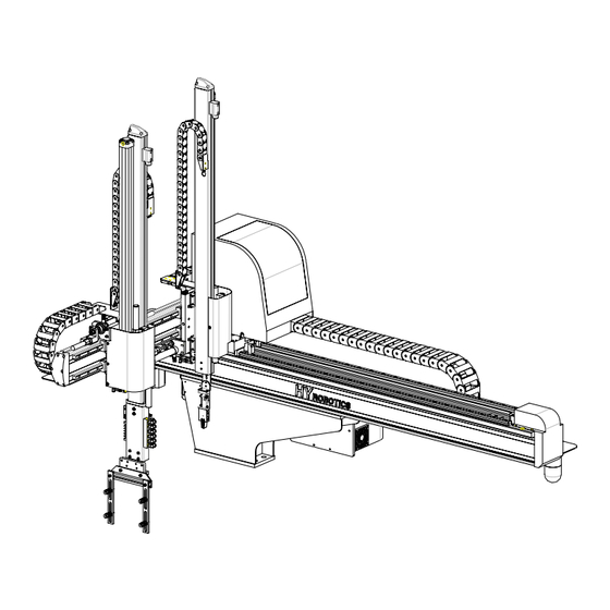
1. Introduction 1.1 Robot Assembly This Robot is consisted of Robot Body Interlock and Control Box Handy Controller Robot Body Control Box Injection Molding Machine Handy Controller TSα Series User Manual 3... -
Page 24: Robot Body
1. Introduction 1.2 Robot Body Sub Arm Main Arm Taking out sprue For Up/Down Movement Valve Box Solenoid Valve and Signal Kick I.O and Vacuum Sensor are Main and Sub Arm installed. forward and backward Traverse traverse movement Jig Unit Sub Arm Grip Control Box Regulator... -
Page 25: Handy Controller Function
1. Introduction 1.3 Handy Controller Function ROBOT EMO Button Press ROBOT EMO Stop will stop operation of Robot and Activate IMM EMO Stop ( Emergency ) LED Display Display current operation status, error message, initial settings Function Keys These keys are used to access each setting screen and to switch between Auto and Manual Mode. -
Page 26: Interlock And Control Box
1. Introduction 1.4 Interlock and Control Box Interlock control box communicate and interlock the signal between the injection molding machine and the take-out robot. When robot is in use, connect the Plug to USE Socket, when robot is not in use ( Operate IMM only ) , move the Plug to Not Use socket. -
Page 27: Each Axis
1. Introduction 1.5 Each Axis Sub Arm Up/Down Main Arm Up/Down Traverse Vacuum, Chuck, Nipper Sub Arm Grip EOAT Rotation Main Arm Kick/Return Sub Arm Kick/Return TSα Series User Manual 7... -
Page 29: Before Operation
2 Before Operation... -
Page 31: Before Operation
2. Before Operation 2.1 Before Operation 2.1.1 Air regulator Knob 1. Make sure the robot arm is retracted Beware that the robot may move suddenly as the system is pressurized. Gage 2. Turn Cock counterclockwise 3. Pull Up the adjusting knob and adjust the Cock pressure to [5.9 ×... -
Page 32: Vacuum Verification Sensor Adjustment
2. Before Operation 2.1.2 Vacuum Verification Sensor Adjustment Set Button k P a Digital Display Mode Selection [Main Arm Up/Down] Vacuum Sensitivity Adjustment ( Normally not required ) STEP 1 k P a Press at the same time P1 will blink. STEP 2 k P a Press... -
Page 33: Before Starting (Preventative Maintenance Schedule)
2. Before Operation 2.2 Before Starting (Preventative Maintenance Schedule) Before you start daily operation of the robot, perform preventive maintenance - Daily Check air Pressure is 5~6.5 kg/cm or 5 ~ 7 × 10 Pa(Gauge)] Inspecting filter regulator unit : Check the bowl for water and contamination and for correct pressure. - Page 34 2. Before Operation Inspect each axis cylinder, make sure operation and the cushion is working properly Inspect body for any damage during mold set up or other operation. 14 TSα Series User Manual...
-
Page 35: Adjust Kick/Return Cylinder
2. Before Operation 2.3 Adjust Kick/Return Cylinder Adjust the location of Kick Cylinder with Kick shock absorber block and bolts This information is designed for main arm. Follow same step for sub arm as described below. STEP 1 Turn off Power and depressurized system with air regulator or disconnect air. - Page 36 2. Before Operation STEP 4 Block Push Block to the kick cylinder guide ( Till the end of Shock Absorber Stroke ) . Tighten the bolts of block Bolts Shock Absorber STEP 5 Loosen the bolts. Block Bolts STEP 6 Adjust main arm location and find return position for application.
-
Page 37: Down Stroke Adjustment
2. Before Operation 2.4 Down Stroke Adjustment Adjust the stroke for Down Position with Stopper This information is designed for main arm. Follow same step for sub arm as described below STEP 1 Turn off Power and depressurized system with air regulator or disconnect air. -
Page 38: Speed Control For Down, Kick, Rotation
2. Before Operation 2.5 Speed Control for Down, Kick, Rotation STEP 1 Normally it is not necessary to adjust speeds because they are factory set. Power On and pressurized system with air regulator or connect air. STEP 2 HY Logo will displays and move to Servo Origin screen. - Page 39 2. Before Operation STEP 4 Speed Control for Kick Fast Slow To adjust the Kick Cylinder speed, use speed Speed Control Valve 1 control Valve 1. To adjust the Kick Return Cylinder speed, use speed control Valve 2. Speed Control Turn the speed controller clockwise to reduce Valve 2 the speed and counterclockwise to increase...
- Page 40 2. Before Operation Set Slow Down Speed first and then set down speed. Valve Description Main Arm Down In Mold Descent Speed Sub Arm Down Main Arm Up Ascent Speed Sub Arm Up Main Arm Slow Down Outside of Mold Descent Speed ( Slow Down ) Sub Arm Slow Down 20 TSα...
-
Page 41: Start Up / Stop
3. START UP / STOP... -
Page 43: Step For Start-Up
3. Start up/Stop 3.1 STEP FOR START-UP Follow step for Auto Mode Power ON Origin Manual Mode Auto Mode TSα Series User Manual 23... -
Page 44: Start Up
3. Start up/Stop 3.2 Start Up STEP 1 Turn On Power.. STEP 2 It will display System Version. And move to origin screen. TOPⅣ Ver1.0 TSα Ver2.00 Before operate Servo Origin, make sure the robot arm is in safe location. If robot arm is not if safe location, move robot arm manually to safe location with manual button. -
Page 45: Stop Operation
3. Start up/Stop 3.3 Stop Operation Follow the next step to stop the robot. Power off and Disconnect air. STEP 1 AutoMod Press for Manual Mode. >Down It will stop the operation after finish to run last step. And moves to Kick Manual Mode. -
Page 46: Emergency Stop ( Emo Stop )
3. Start up/Stop 3.4 Emergency Stop ( EMO Stop ) Press ROBOT EMO button in any dangerous situation ( Protect People, Robot, Mold Etc ) STEP 1 Pressing ROBOT EMO button. Robot will move to waiting position and stop Operation. Error Alarm and buzzer will be on and Error message will appear in the 0 9 7 R O B O T E M O... -
Page 47: Operation
4 OPERATION... -
Page 49: Screen Structure
4. Operation 4.1Screen Structure Initial Input/Output Motion Timer Setting T0 Kick Delay Arm Selection T1 Chuck Delay Take Out Method Manual Mode Timer T2 Kick Return Delay Outside Waiting T3 Sub Arm Release Counter Motion Pattern T4 Main Arm Release Step run Main Arm Down T5 Up Delay... -
Page 50: Initial Screen
4. Operation 4.2 Initial Screen Power on displays Logo and Robot Name/type , Robot Initialization and Move Origin Point Selecting Outside Waiting Option will initiate Robot move to the selected location ( Outside of Mold ) TSα Ver 2.00 30 TSα Series User Manual... -
Page 51: Searching Robot Origin Point
4. Operation 4.3 Searching Robot Origin Point (1) Description Robot will operate with following step to search origin point. 1. Ascent, 2. Kick Return, 3. Rotation Return, 4. Swivel Return and 5. Traverse Axis search origin point ( This Step is developed to have more safety movement when restart robot ) Selecting Outside Waiting Option will initiate Robot move to the selected location ( Outside of Mold ) . -
Page 52: Manual Mode
4. Operation 4.4 Manual Mode (1) Description In the Manual Mode , robot can be operated with manual operation key. Selecting Outside Waiting Option will initiate Robot to move to the selected location CLEARING ROBOT MOTION AREA : It is the responsible of the operator to verify that the robot motion area is clear before any robot operation. - Page 53 4. Operation (2) Button Function Do not enter robot motion area. If anyone enter the robot motion area during Auto Mode or Manual Mode, serious accident could results. Robot arm will not descent if mold is not open. Button Description Press Timer button, LCD displays timer mode for delay time settings.
- Page 54 4. Operation Button Description Press Chuck Chuck , Press again, Chuck Off Press Suction Suction, Press again, Suction Off Press Swivel. Swing Chuck, Press again, Chuck swing return. Press Descent Button for Sub Arm Move Sub Arm Down, Press again, Move Sub Arm up Press Kick Button Move Sub Arm Kick, Press again, Move Sub Arm Kick Return Press Gripper...
-
Page 55: Timer Set Up
4. Operation 4.1.1 Timer Set Up (1) Description Timer setup will control the Robot motion smoothly with Injection Molding Machine Operation. Timers will not be saved separately with Mold Files. For examples setting T0 as a 0.2 Seconds will make all other mold file use T0 as 0.2 Seconds Timer T0 Kick T1 Chuck... - Page 56 4. Operation Default Display Description ( sec ) Kick After starting Down, Delay time for Kick Movement Chuck Chuck Delay KicRt Kick Return Delay SOpen Sub Arm Release MOpen Main Arm Release Ascent(Up) Delay NiCls Nipper Close Cutting Delay – Robot Nipper, External Nipper CutDl Nipper Far –...
- Page 57 4. Operation (2) Button Function Button Description ‘<’ key moves up and down to select each Timer. Numeric Key Input delay time. Press the Enter Button to save the change Cancel the Input Stop Auto Mode and Back to Manual Mode Pressing Auto Button will back to Auto Mode TSα...
- Page 58 4. Operation (3) Programming Timer Settings Timer settings can be viewed and changed using the handy controller under two conditions. 1. When the robot is in Timer Mode. 2. During Auto Mode (While Robot is running) Timer can be changed during Auto Mode, but cannot be changed during Cycle and Step Operation.
-
Page 59: Counter
4. Operation 4.1.2 Counter (1) Description Counter can be viewed and changed using handy controller. Counter Mode displays Total Production Quantity , Detection Failure Quantity, Multi Point Release. Counter >C0 10000 TotQty DetFai C2 MulRel Display Description Total Operation ( Production ) Quantity y : Robot Operation Cycle after TotQty Reset DetFai... - Page 60 4. Operation (3) Counter Reset Method Counter can be changed during Auto Mode, but can not be changed during Cycle and Step Operation. Resetting C0 to 0 STEP 1 Manual ◀30%▶ Press, with key , it displays Counter screen. STEP 2 Counter >C0 10000...
-
Page 61: Motion Mode
4. Operation 4.1.3 Motion Mode (1) description Robot motion pattern can be decided by selecting of Each Motion Mode. ArmSet M&S ◀ Method Vacuum OutWait NoUse Motion LType The below icons uses for robot motion in this book Origin Chuck Chuck Off Vacuum Vacuum... - Page 62 4. Operation Robot Arm Setting ① ArmSet : Robot Arm Setting Setting for Take-Out Motion Arm. Default setting is “M&S”. ArmSet M&S ◀ Method Vacuum OutWait NoUse Motion LType Display Description Motion Sub Arm Main Arm M&S Select Main and Sub for Both Arm (=Default) opeartion Main Arm...
- Page 63 4. Operation ② Method Setting take out method, Vacuum, Chucking. Default setting is “Vacuum”. ArmSet M&S Method Vacuum ◀ OutWait NoUse Motion LType Display Description Motion Vacuum Take Parts with Vacuum (=Default) Operation. Vacuum Chuck Take out Parts with Chuck Operation. Chuck Chuck Take out Parts with Vacuum and...
- Page 64 4. Operation ③ Outside Waiting OutWait : Outside Waiting When many other auxiliary products are attached on the top of the mold, robot might not able to wait on the top of the mold until the mold is completely open. Robot has function to wait outside of IMM, and robot will move to IMM after mold is completely open.
- Page 65 4. Operation ④ Motion Pattern There is two type of motion, L and U type. L type is 1.Down, 2 Kick, 3 Vacuum or Chuck, and Out and U type is 1.Down, 2.Vacuum or Chuck 3. Kick Return and Out. Main and Sub arm set together.
- Page 66 4. Operation ⑤ Main Arm Descent ( Down ) MArmDn : Main Arm Descent ( Down ) Main Arm Descent position can be set up at either nozzle side or clamp side. Default setting is “Nozzle”. MArmDn Nozzle ◀ SArmDn Clamp EOATRot BeforeT MArmOff...
- Page 67 4. Operation ⑥ Sub Arm Descent ( Down ) SArmDn : Sub Arm Descent ( Down ) Sub Arm Descent position can be set up at either nozzle side or clamp side. Default setting is “Clamp” MArmDn Nozzle SArmDn Clamp ◀...
- Page 68 4. Operation ⑦ EOAT Rotation EoatRot : EOAT Rotation, means Chuck(EOAT) rotation time setting. Default setting is “BeforeT”. ( Before Traverse ) MArmDn Nozzle SArmDn Clamp EOATRot BeforeT ◀ MArmOff Display Description Motion Before T : Before Traverse Movement. BeforeT EOAT unit rotates...
- Page 69 4. Operation After T : After Traverse, AfterT After Traverse and Kick, EOAT Rotate. NoRot No EOAT Rotation TSα Series User Manual 49...
- Page 70 4. Operation ⑧ Main Arm Release( Off ) MArmOff : Main Arm Release( Off ), Set Main Arm Off(Parts Release) Timing Default setting is “Off”. MArmDn Nozzle SArmDn Clamp EOATRot BeforeT MArmOff ◀ Display Description Motion Main Arm Traverse and Descent ( Down ) and Main Arm (=Default) Release ( Off ) the...
- Page 71 4. Operation ⑨ Sub Arm Release( Off ) SArmOff : Sub Arm Release( Off ), Set Sub Arm Off(Parts Release) Timing. Default setting is “Off”. SArmOff ◀ EjtCtrl NoUse Alarm SpecialSetting Display Description Motion Sub Arm Traverse Release(Off) (=Default) Runner ( Sub Arm ) Sub Arm Sub Arm Release (Off) while TrvOff...
- Page 72 4. Operation ⑩ Ejector Control When Automate Thin Plate Molded Products or Products can be drop with Ejector Kick Operation easily, Robot can control IMM Ejector. Default setting is “NoUse”. SArmOff EjtCtrl NoUse ◀ Alarm SpecialSetting Display Description Motion EOAT Ejector Pin NoUse Ejector is controlled by IMM...
- Page 73 4. Operation ⑫ Multi Point Off MulOff: Multi Point Off Each cycle can release ( Off ) part in a different location ( Position ) with specified distance with Multi Point Off Function. Default setting is “NoUse”. If “USE” , Default number of point is “...
- Page 74 4. Operation ⑬Order Point Off (Option) OrdOff : Order Point Off When there are more than 2 cavity products in the mold, each cavity part can be released different position with Order Point Off Option. Default setting is “NoUse”. If “Use” , Number of Cavity is “ 2 “ OrdOff NoUse ◀...
- Page 75 4. Operation ⑭Mold Close Delay MdClos : Mold Close Delay Robot can delay the mold close, after taking out the parts from the mold, ascent, until traverse movement to set position . Default setting is “NoUse”. Position can be set in the range of No Down Range.
- Page 76 4. Operation ⑮Flee ( Optional feature ) : Some other robot company says this feature as Undercut After Chuck or Suction the parts in mold, robot can move traverse axis ( -X+) or up in mold so that parts can escape from core and Ejector attachments to take out from the mold. Default setting is “NoUse”.
- Page 77 4. Operation ○ Pitch Change(Option) When robot release (off) parts with different pitch of the part’s pitch of the mold, additional EOAT can be added with cylinder to change the pitch distance of the release ( off ) Default setting is “NoUse”. This is optional feature, Contact factory to add this feature.
- Page 78 4. Operation ○ Vertical Swivel (Option) Set the Swivel operation timing. ( Robot EOAT can Rotate with Vertical Axis ) Default setting is “NoUse”. MdClos NoUse Flee NoUse Pitch NoUse Swivel Swivel ◀ Display Description Motion Main Arm NoUse Not in Use (=Default) Robot EOAT swivel in mold and Ascent ( Up ) and Swivel Return.
- Page 79 4. Operation ○ Process Time ( Production Time) PTime : Process Time This time is for 1 total cycle of the production. If exceed error this time, it occur Process Time Error. Set time as “0” second will not occur any error. Default setting is 0 sec. Ptime 0 sec ◀...
- Page 80 4. Operation ○ External Nipper ( Need Nipper Cutting Attachement Required ) ExNipp : External Nipper Robot can send signal of cutting sprue or nipper operating to Nipper Cutting machine Default setting is “NoUse”. Ptime 0 sec RoNipp NoUse ExNipp NoUse ◀...
- Page 81 4. Operation Display Description Motion ⑥ ⑦ Nipper cutting equipment ① ⑪ ⑤ built in out side of mold ⑧ ○ ② ⑩ ExCut2 to cut sprue and runner. ④ ⑮ ③ ⑨ ( Need Nipper Cutting ⑫ ⑭ Machine ) ⑬...
- Page 82 4. Operation (3) Mode Confirmation Example ) Change from the suction to Chuck for TakeOut Method STEP 1 Manual ◀30%▶ In manual Molde, Press , move to mode screen STEP 2 ArmSet M&S ◀ Method Vacuum , moves “◀” to Method Item. Press OutWait NoUse...
-
Page 83: Creating Mold File
4. Operation 4.1.4 Creating Mold File (1) Description Search Mold Number MoldNo Input Mold Number 0 0 0 (2) Button Function in Mold Number screen Button Description Numeric Key Input Mold Number Change to Manual Mode Cancel the Input Number Change to Mold Manager screen with selected Number TSα... - Page 84 4. Operation (3) Mold Manager Select , Create and Delete Mold File. MoldMgr >00 FREE MODE 01 RUN_L 02 RUN_U (4) Each Button Function in Mold Manager screen Button Description Open Mold File. Select 0 file can create any motion pattern and mode which can be created by user and move to New Mold screen and save with Mold Number and name.
- Page 85 4. Operation (5) New Mold Save the motion pattern in the mode with new mold number and name. NewMold Mold Name 0 FILE05 Mold Number (Auto Create) (Auto Create) (6) Button Function in New Mold Button Description Numeric Key Pressing the numeric key while blinking Mold Number will Input Number Pressing Enter to save Mold Number and Name Press to scroll the cursor on the mold number.
- Page 86 4. Operation (7) Creating Mold File Creating Mold file with new motion pattern. STEP 1 Manual ◀30%▶ Press and move to mold Number screen STEP 2 MoldNo I n p u t Press to change mold maintenance mode.. M o l d n u m b e r 0 0 0 STEP3 MoldMgr...
- Page 87 4. Operation STEP 7 NewMold Press , select Character 06 A It will displays A~Z, 0~9, _, -, STEP 8 NewMold Press to save data 06 A Press will move cursor to left side and, Change the text with pressing button.
-
Page 88: Delete Mold File
4. Operation 4.1.5 Delete Mold File (1) Description Delete Mold File that created before. Currently open mold file can not be deleted. MoldDel Selected 51 PHONE Mold File D e l e t e ? [ Y ( ) / N ( S t o p ) ] (2) Button function in Mold Delete Mode Button Description... - Page 89 4. Operation (3) Delete Mold File STEP 1 Manual ◀30%▶ Press move to mold search screen. STEP 2 MoldNo I n p u t Press and move to mold maintenance screen M o l d N u m b e r . STEP 3 MoldMgr >50 SONATA...
-
Page 90: Setting Basic Motion Pattern
4. Operation 4.1.6 Setting Basic Motion Pattern (1) Description of Basic Motion Pattern The Motion pattern for simple and popular operation are already memorized in the system Can change some mode from the similar operation that want to create, and setting. SArmDn Nozzle ◀... - Page 91 4. Operation Method Chuck ◀ MArmDn Nozzle EOATRot BeforeT [03 Main_L, 04 Main_U] type Motion ③ 03 Main_L Main Arm Only (L type) Item Mode ArmSet MainArm Method Chuck OutWait NoUse Motion LType MArmDn Nozzle SArmDn EOATRot BeforeT MArmOff SArmOff EjtCtl Alarm ④...
- Page 92 4. Operation ArmSet Vacuum ▶ MArmDn Clamp SArmDn Nozzle EOATRot BeforeT [05 MS_L, 06 MS_U] type Motion ⑤ 05 MS_L Main and Sub Arm (L type) Item Mode ArmSet M&S Method Vacuum OutWait NoUse Motion LType MArmDn Nozzle SArmDn Clamp EOATRot BeforeT MArmOff...
- Page 93 4. Operation (2) Selecting Basic Motion Pattern Example) Arm Selection(M&S), Take Out Method(Vacuum), Outside Waiting(NoUse), Motion Parttern(LType), Main Down(Clamp), Down(Clamp), EOAT Rotation Timing(BeforeT) STEP 1 Set Mold Number 5 which is similar with Example except Main Arm Down. Main Arm Sub Arm STEP 2 Manual...
- Page 94 4. Operation STEP 6 Method Vacuum ◀ MArmDn Nozzle moves “▶”to EOATRot(EOAT Rotation), Press SArmDn Clamp Press change Main Down EOATRot BeforeT BeforeT(EOAT Rotation Before Traverse). STEP 7 Method Vacuum MArmDn Clamp ◀ Press to move to Manual Mode screen. SArmDn Clamp EOATRot...
-
Page 95: Step Run
4. Operation 4.1.7 Step Run (1) Description Step Run will operate the robot step by step of each motion. After origin, will not displays “>” cursor, pressing will displays “>” at the first step. StepRun >Down Kick ChuckON (2) Button Function Button Description Press Down Arrow Key will Operate Step Operation. -
Page 96: Input And Output Signal Check
4. Operation 4.1.8 Input and Output signal check (1) Description Confirm Input, Output, Interlock. I n p u t ( O u t ▶ ) O u t p u t ( I n ▶ ) IA0MArmDownOk ● IA0MArmDown ● IA1MArmUpOK ○... - Page 97 4. Operation Input Output Display Description Display Description PitchChg Pitch Change Flee Traverse (Flee) in Mold MSlowDown Main Arm Slow Descent Nipper Nipper (Internal. External) Slow SSlowDown Descent(Down) OD6 ExNipCls External Nipper Close ReadyCut Ready to Cutting CutStart Cutting Start RdyStack Ready to Stacking StackingOK...
-
Page 98: Position Set With Number Input
4. Operation 4.1.9 Position Set with Number Input (1) Position Nipper ON Origin and Waiting Position Main Arm Release Position Take out position Sub Arm Release position Reject Position Basic Position Description Sub Arm Release Release(Off) position for Sprue or Runner Position Defective Parts Release (Off) Position ( Signal Required from Reject Position... - Page 99 4. Operation (2) Description In the auto mode, each position can change within ±100mm, The robot will have only one of Each position value . Origin and Take out position is 0 mm, do not required to set. Number 0000 >P0SubOff 0000mm P1RjtOff...
- Page 100 4. Operation (4) Example Set Sub Arm Release Position to 1000mm STEP 1 Manual ◀30%▶ Hold and press , move to Mold Number screen. STEP 2 Number 0000 >P0SubOff 900mm Press to input 1000, Press to save P1RjtOff 1100mm Position data. P2NipOn 1100mm STEP 3...
-
Page 101: Position Setting With Jog Input
4. Operation 4.1.10 Position Setting with Jog Input (1) Description Press set each position value 30 0000 P0SubOff ◀30%▶ Manual Mode Speed 0000mm < 0000mm (2) Button Function Button Description Reduce Speed 30%, 20%, 10%, 5% 10mm, 1mm Increase Speed Move cursor to up or down item Traverse Movement ( X+) Traverse Return Movement ( X-) - Page 102 4. Operation (3) Position setting with Jog Key Set Reject Position to 100mm. Manual STEP 1 ◀30%▶ Hold and press , move to Mold Number screen. STEP 2 Numbmer 0000 >P0SubOff 0000mm Hold and press again, move to Jog Input screen. P1RjtOff 0000mm P2NipON...
-
Page 103: Speed Setting
4. Operation 4.1.11 Speed Setting (1) Description Setting Robot Movement ( -X+) Speed in Auto Mode 0000 Speed > S0 SubOff S1 RjtOff S2 NipOn Display Description SubOff Speed ( When Robot moves to Sub Arm Release(Off) Position. ) Reject Speed ( When robot moves to Defective ( Reject) Position. - Page 104 4. Operation (3) Example Set Sub Arm Release Position to 100%. STEP 1 Manual ◀30%▶ Hold and press , move to Number Input screen. STEP 2 Number 0000 >P0SubOff 0000mm Pressing changes Speed Input screen. P1Reject 0000mm P2NipOn 0000mm STEP 3 0000 Speed S0 SubOff...
-
Page 105: Auto Mode
4. Operation 4.5 Auto Mode (1) Description AutoMod P r e s s A u t o > Down B u t t o n t o Kick O p e r a t e A u t o ChuckON M o d e [Auto Message] [Auto Mode screen]... -
Page 106: Error Log
4. Operation 4.6 Error Log (1) Description ErrLog 1/40 0 4 / 0 4 / 1 5 13:11:25 1 5 2 EOAT Rotate (2) Each Button Function Button Description Move the cursor to different error log. Change to the Manual Mode Change to the Auto Mode (3) Checking Error Log ErrLog... -
Page 107: Version Information
4. Operation 4.7 Version Information (1) Description Check Version Information. Version TP V 0 2 . 0 0 SC V 0 2 . 0 0 IF V 0 1 . 0 0 (2) Each Button Function Button Description Change to the Manual Mode Change to the Auto Mode (3) Checking Version Information STEP 1... -
Page 108: Time For Arm Slow Down
4. Operation 4.8 Time for Arm Slow Down (1) Description Operation of Robot arm descent operate with two solenoid valve for high speed operation. One of these two valve can change the off timing so that robot can minimize shock in the structure and increase life cycle time. -
Page 109: Error Recovery
4. Operation 4.9 Error Recovery (1) Error Description Displays error recovery method. Error 152 EOAT Rotate Check EOAT Rotate IA4 (2) Each Button Function Button Description Press Clear button, Stop Alarm and Buzzer , Press again Clear button error message. (3) Error Recovery STEP 1 Error... -
Page 110: Change Language
4. Operation 4.10 Change Language Press at the same time, change Korean, English, Chinese. 90 TSα Series User Manual... -
Page 111: Robot And Program Maintenance Screen
4. Operation 4.11 Robot and Program maintenance Screen Turn power on with pressing Screen Mode Order Default/Setting Description Limit for - Traverse Limit Range Traverse + Traverse Limit Range No Down Range No Down Range In Mold Traverse Traverse Limit in Mold ±20mm Limit Origin... - Page 112 4. Operation ① NoUse defective Input Reject (=default) don’t separate reject part by robot ② defective Input activate Robot to separate reject part to set position Total ① Enter will delete Mold (=default) mold file Delete ② Enter will delete All mold file Error Log ①...
-
Page 113: Waiting Device (Option)
4. Operation 4.12 Waiting Device (Option) (1) Dscription This is a device fabricated to adjust the Kick/Return position of Main and Sub Arm with remote controller. ▲ Main BodyFwd BodyBwd S:Swt StopFwd StopBwd Sub Arm Main dsArm Body Forward Body Forward Stopper Forward Stopper Forward (2) Button Function... -
Page 115: Follow Up
5 Follow Up... -
Page 117: Motion Pattern Selection
5. Follow Up 5.1 Motion Pattern Selection ⑮ ⑦ ⑧ ① ⑨ ⑭ ⑥ ⑩ ② ③ ⑬ ⑤ ⑪ ④ ⑫ ①. Down ⑨. Main Arm Release Position ②. Kick ⑩. EOAT Rotation ③. Chuck ON ⑪. 2 Descent ④. -
Page 118: Start Up
5. Follow Up 5.2 Start Up STEP 1 Turn On Power. STEP 2 Displays Logo and moves to Origin screen. TSα Ver 2.00 5.3 Move to Origin Before operate Servo Origin, make sure the robot arm is in safe location. If robot arm is not if safe location, move robot arm manually to safe location with manual button. -
Page 119: Set Position
5. Follow Up 5.4 Set Position Nipper ON Origin and Waiting Position Main Arm Release Position Take out position Sub Arm Release position Reject Position STEP 4 Manual ◀30%▶ [Move to Number Input screen] Press , moves to Number Input screen. STEP 5 Number [Move to Jog Input screen.]... - Page 120 5. Follow Up STEP 6 [Set Sub Arm Release Position] P0SubOff ◀10%▶ Press , move Sub Arm to the Parts Release (Off) 0mm < Position. * Press to adjust Manual Mode speed. Can set up 30%, 20%, 10%, 5% of Normal Speed. Distance can be set 10mm, or 1mm.
- Page 121 5. Follow Up STEP 11 1000 P2 NipOn ◀10%▶ Press , save current value to set. 1000mm < 1000mm Press , move to Main arm release ( Off ) setting screen. STEP 12 1000 [Set Main Arm Release Position] P3 MaiOff ◀10%▶...
-
Page 122: Speed Setting
5. Follow Up 5.5 Speed Setting STEP 16 Number [Set Main Arm Release Speed to 100%] >P0SubOff 750mm P1RjtOff 750mm Press with at the same time, move to the number input P2NipOn 1000mm screen. STEP 17 Speed >S0SubOff 80 % Press , move to speed input screen. -
Page 123: Timer Setting
5. Follow Up 5.6 Timer Setting Sub Arm Default Display 0 sec Kick Main Arm 0 sec Chuck 0 sec KicRt 0.5 sec S-Off 0.3 sec M-Off 0.3 sec UpDly 5 sec Conve Ejector Conveyor STEP 19 Timer [Move to timer screen, set T0 chuck delay 0.3 sec] >T0 Kick 0.0 <... -
Page 124: Mold Create
5. Follow Up 5.7 Mold Create STEP 21 MoldNo Input Hold and Press , displays Mold search mode. Mold number Press moves to mold manager screen and cursor will be on 0. STEP 22 MoldMgr > 0 FREEMODE Pressing on the 0 Mold (Free mode) and moves to mode 01 RUN L screen. -
Page 125: Step Run
5. Follow Up STEP 27 Manual ◀30%▶ Press will create Mold File and moves to Manual Mode. 5.8 Step Run STEP 28 StepRun >Down Pressing , move to Step Run screen. Kick Pressing will operate motion step by step. ChuckON Press and moves to Manual Mode. -
Page 127: Error
6 Error... -
Page 129: Error Screen
8. Error 6.1 Error Screen This Chapter describes Error Code and Error recovery method. Error Error Code EOAT Rotate Error Description Check EOAT Error Recovery Method Rotate IA4 Error cause Alarm and Buzzer, display the error message. Press Stop Alarm and Buzzer, Press again clear error messages. -
Page 130: Motor Related
8. Error 6.2.2 Motor Related Display Cause Recovery Method TrvsCWLimt Traverse Movement stop by Operate robot arm to other touching CW Limit Proximity direction ( End of Stroke ) Sensor. TrvsCCWLimt Traverse Movement stop by Operate robot arm to other touching CCW Limit Proximity direction ( End of Stroke ) Sensor. -
Page 131: Pneumatic
8. Error 6.2.3 Pneumatic Display Cause Recovery Method 128 SKick/RtSame Sub Arm Kick and Runner Check Sub Arm Kick and Runner Kick Return Sensor Kick Return Sensor confirm(OK)at the same time 129 MKick/RtSame Main Arm Kick and Runner Check Main Arm Kick and Kick Return Sensor Runner confirm(OK)at the same time... -
Page 132: Sol Valve
8. Error 6.2.4 Sol valve Display Cause Recovery Method 1. Open Safety Door and Fix VacuumFail A. Vacuum Failure Problem in Manual Mode B. Check Vacuum Pad 2. Replace Pad. C. Leaking at Stem and 3. Tight Stem and Fitting Screw Fitting D. -
Page 133: Interlock Related
8. Error 6.2.6 Interlock Related Display Cause Recovery Method 202 MoldOpenOk Rarely some Molding Machine 1. Reboot lose Mold Open Complete 2. Contact Factory Signal momentarily when Robot arm in Take-Out Position. 6.2.7 Operation Error Display Cause Recovery Method 208 ArmIsNotUp Traverse Movement without Ascent Main and Sub Arm Up ( Ascent ) Complete... -
Page 135: Appendix
Appendix... -
Page 137: Specification
Appencix A. Specification Power Control Method Pneumatic Pressure 100Vac–240Vac 50/60Hz Sequence Program 0.5 to 0.6 Mpa Maxim Kick stroke Descent stroke Traverse stroke (mm) Applicable Robot Take- Entire (mm) (mm) Pneumatic Noise injection body weight out dry MODEL consumptio level molding weght capaci... -
Page 138: External Dimension
Appendix B. External Dimension B.1 TSα-200DI dimension (Unit: mm) Type 200SI 200DI 118 TSα Series User Manual... -
Page 139: Tsα-300Di Dimension
Appencix B.2 TSα-300DI dimension (Unit: mm) Type 300SI 1005 300DI TSα Series User Manual 119... -
Page 140: Safe Guarded Space
Appendix C. Safe guarded space C.2 TSα-200DI (Unit: mm) Type 200SI 200DI 120 TSα Series User Manual... -
Page 141: Tsα-300Di
Appencix C.2 TSα-300DI (Unit: mm) Type 300SI 1173 1273 300DI 1043 1243 TSα Series User Manual 121... -
Page 142: Air Chart
Appendix H. Air Chart 122 TSα Series User Manual... - Page 144 #144BL 11LOT NAMDONG INDUSTRIAL COMPLEX. 716-10 GOJAN-DONG NAMDONG-KU INCHON KOREA TEL:+82-32-814-5040 FAX:+82-32-811-9978 www.hyrobot.com...
Need help?
Do you have a question about the TSa-200SI and is the answer not in the manual?
Questions and answers