
Related Manuals for Agilent Technologies 1290 Infinity II 2D-LC


Summary of Contents for Agilent Technologies 1290 Infinity II 2D-LC
- Page 1 Agilent 1290 Infinity II 2D-LC Solution MassHunter Acquisition for TOF and Q-TOF User Guide 2D-LC User Guide...
- Page 2 CAUTION beyond a notice until ble for errors or for incidental or conse- sent from Agilent Technologies, Inc. as the indicated conditions are fully quential damages in connection with the governed by United States and interna- understood and met.
- Page 3 Installation This chapter describes the hardware and software installation of the Agilent 1290 Infinity II 2D-LC Solution. The 2D-LC instrument can be used with the software described in this document. The installation instructions are valid for the modes standard heart-cutting, multiple heart-cutting, high resolution sampling and comprehensive 2D-LC.
- Page 4 This chapter provides information on how to develop methods when using Active Solvent Modulation (ASM). Run the System This chapter describes how to run the Agilent 1290 Infinity II 2D-LC Solution in the modes standard heart-cutting, multiple heart-cutting, high resolution sampling and comprehensive 2D-LC with the driver-based 2D-LC Solution.
-
Page 5: Table Of Contents
Contents Introduction Product Description Features Terms related to 2D-LC Concepts of 2D-LC Concepts of 2D-LC Heart-Cutting 2D-LC (LC-LC) Multiple Heart-Cutting and High Resolution Sampling 2D-LC Comprehensive 2D-LC (LCxLC) Triggering of 2D-LC Active Solvent Modulation (ASM) Compatibility Matrix Supported Chromatographic Data Systems Supported Drivers Supported Operating Systems Supported Firmware... - Page 6 2D-LC Data Acquisition in MassHunter Workstation 11 Start the Data Acquisition Software Overview 2D-LC in MassHunter Acquisition 11 Instrument Status 2D-LC User Interface 2D-LC Valves Online Monitor in the 2D-LC User Interface Method Editor Window Sample Run Window Worklist Window Tune Window Instrument Details Log book in MassHunter Acquisition 11...
- Page 7 Run the System Familiarization to Start a System Run Prepare the 2D-LC System Configure the 2D-LC System Checkout Familiarization Procedure Prepare the Experiment Run the Experiment Data Analysis 2D-LC Data Analysis/Data Evaluation for MassHunter GC Image Basic Information Troubleshooting and Diagnostics Overview of the Module’s Indicators and Test Functions User Interfaces Agilent Lab Advisor Software...
- Page 8 Maintenance Introduction to Maintenance Warnings and Cautions Overview of Maintenance Cleaning the Module Correcting Leaks Replace Valve Heads Replacing Parts of the Valve Head Replacing the Fuses of the Infinity Valve Drive Parts for Maintenance 2D-LC Loops 2D-LC Capillaries ASM Capillaries Pressure Release Kit 2D-LC Easy Starter Kit Valve Drive Parts...
- Page 9 Theoretical basis of 2D-LC 2D as detector Successful Mode Combinations Solvent Elution Modes Practical Issues Appendix General Safety Information Waste Electrical and Electronic Equipment (WEEE) Directive Radio Interference Sound Emission Solvent Information Further Information Agilent Technologies on Internet 2D-LC User Guide...
-
Page 10: Introduction
Introduction Product Description Features Terms related to 2D-LC This chapter describes the product of Agilent 1290 Infinity II 2D-LC Solution. 2D-LC User Guide... -
Page 11: Product Description
Introduction Product Description Product Description The 1290 Infinity II 2D-LC System is an innovative solution for solving most complex separations, analyzing complex samples, and simplifying complex workflows. From separation of a few co-eluting compounds to mixtures of highest complexity - Agilent 2D-LC Solutions allow choosing from 2D-LC modes (multiple) heart-cutting with high-resolution sampling and comprehensive 2D-LC. -
Page 12: Features
Introduction Features Features Agilent InfinityLab 2D-LC Solutions offers following key features: • Agilent 2D-LC is based on 1290 Infinity II Systems with UHPLC performance, fast gradients, high sensitivity and excellent robustness • Dedicated 2D-LC valves use completely symmetric flow paths for reproducible retention times and peak areas. - Page 13 Introduction Features • Multi-inject speeds up such analyses by sequentially injecting cuts from multiple sample loops. • Smart peak parking optimizes runs for the highest possible number of cuts and shortest run time. • A wide range of first and second dimension solvents and gradients can be combined with the optional Agilent Active Solvent Modulation Technology for multiple heart-cutting and high-resolution sampling measurements.
-
Page 14: Terms Related To 2D-Lc
Introduction Terms related to 2D-LC Terms related to 2D-LC Term Definition 2D-LC Two-dimensional liquid chromatography One-dimensional 1D-LC is the classical (one dimensional) chromatography, which provides one-dimensional data. Usually, you would not even think about dimensions in the 1D world. First dimension For example, a D column is the column used in the first dimension, and a chromatogram is the chromatogram acquired for the first dimension. -
Page 15: Concepts Of 2D-Lc
Concept of Time Triggering Active Solvent Modulation (ASM) Introduction to Active Solvent Modulation (ASM) Operating Principle Understanding the ASM Factor Comprehensive 2D-LC and Active Solvent Modulation This chapter describes the concepts of Agilent 1290 Infinity II 2D-LC Solution. 2D-LC User Guide... -
Page 16: Concepts Of 2D-Lc
Concepts of 2D-LC Concepts of 2D-LC Concepts of 2D-LC In a 2D-LC-System, D pump generates the D gradient. An autosampler injects the sample and separates it by D column. A 2D-LC Valve (Injector) connects the first dimension to the second dimension and stores sample peaks intermediately. - Page 17 Concepts of 2D-LC Concepts of 2D-LC In 2D-LC the following concepts exist: • Comprehensive 2D-LC (LC×LC) In LC×LC, the total eluent from the first dimension is injected on to the column in the second dimension. • Heart-cutting 2D-LC (LC-LC) In LC-LC only parts of the eluent from the first dimension are injected on to the column in the second dimension.
- Page 18 Concepts of 2D-LC Heart-Cutting 2D-LC (LC-LC) Heart-Cutting 2D-LC (LC-LC) The following items are characteristic for LC-LC: • Only parts of the effluent of the D column - only the peaks of interest eluted from the D column - are injected to the D column •...
-
Page 19: Multiple Heart-Cutting And High Resolution Sampling 2D-Lc
Concepts of 2D-LC Multiple Heart-Cutting and High Resolution Sampling 2D-LC Multiple Heart-Cutting and High Resolution Sampling 2D-LC Typically, the gradient time in the second dimension is much longer for heart-cutting than with the comprehensive technique. The disadvantage of the standard heart-cutting techniques is that peaks cannot be sampled while a second dimension gradient is still running. - Page 20 Concepts of 2D-LC Multiple Heart-Cutting and High Resolution Sampling 2D-LC This problem is addressed using a setup called multiple heart-cutting 2D-LC. Here, the sampling loops on the 2D-LC valve are exchanged with 6-position/14-port selection valves, which are equipped with six loops each. In this configuration, a peak can be cut out and stored, then analyzed as soon as the second dimension is free.
- Page 21 Concepts of 2D-LC Multiple Heart-Cutting and High Resolution Sampling 2D-LC Peaks that are cut out and stored during a run are analyzed consecutively in the second dimension, even when the first dimension is still running. To avoid carry-over the peaks are analyzed in reverse order of storage in a single Multiple Heart-Cutting Valve.
-
Page 22: Principles Of Heart-Cutting 2D-Lc
Concepts of 2D-LC Multiple Heart-Cutting and High Resolution Sampling 2D-LC Principles of Heart-cutting 2D-LC Multiple Heart-Cutting - Principles Multiple Heart-Cutting - Principles Multiple Heart-Cutting 2D-LC is a complex workflow, working on a special algorithm for filling the sample loops and analyzing the stored cuts, based on different criteria. - Page 23 Concepts of 2D-LC Multiple Heart-Cutting and High Resolution Sampling 2D-LC Peak-based mode in multiple heart-cutting Figure 5 Peak-based mode In peak based mode, three parameters determine how peaks are parked: 1 A trigger indicates, if a peak has been detected, e.g. because a reference signal (if available) exceeds the threshold or the slope as defined in advanced settings.
- Page 24 Concepts of 2D-LC Multiple Heart-Cutting and High Resolution Sampling 2D-LC Time-based mode in multiple heart-cutting Figure 6 Time-based mode MHC Time-based means that heart-cut times are defined in a timetable. This timetable can be constructed according to the first dimension retention time of peaks in a reference chromatogram.
- Page 25 Concepts of 2D-LC Multiple Heart-Cutting and High Resolution Sampling 2D-LC High Resolution Sampling - Peak Parking Principles In the HiRes sampling mode, the multiple heart-cutting (MHC) valve is switched before and after parking the peak. This has the following consequences: •...
- Page 26 Concepts of 2D-LC Multiple Heart-Cutting and High Resolution Sampling 2D-LC Peak parking example for HiRes sampling In High-Resolution sampling, the first loop is a bypass position. When switching to the second loop for the first cut, unknown content may be parked in the first loop, which must be flushed at the end of the unparking procedure.
- Page 27 Concepts of 2D-LC Multiple Heart-Cutting and High Resolution Sampling 2D-LC • Cut number 5 cannot be parked entirely in the sample loop, otherwise cut 6 would go partially to the transfer capillary and would therefore be lost or spoil cut 5 •...
- Page 28 Concepts of 2D-LC Multiple Heart-Cutting and High Resolution Sampling 2D-LC • For parking cut 6 into the sample loop, the cut first needs to be moved from the 2D-LC Valve to the deck valve. • Cut 7 will be parked in loop B2 •...
- Page 29 Concepts of 2D-LC Multiple Heart-Cutting and High Resolution Sampling 2D-LC High-resolution sampling (time-based mode) For high-resolution sampling, a (start) time can be set, the cut size in seconds and the number of cuts for a peak or range. The sampling time should be less than the time which is needed for filling one sample loop corresponding to a loop filling below 80%.
-
Page 30: Comprehensive 2D-Lc (Lcxlc)
Concepts of 2D-LC Comprehensive 2D-LC (LCxLC) Comprehensive 2D-LC (LCxLC) In comprehensive 2D-LC (also known as LC×LC), the total eluent from the first dimension is injected on to the column in the second dimension using two equal-sized sampling loops that are alternated by a switching valve. While the first loop is being filled in the first dimension, the contents of the second loop is analyzed in the second dimension;... - Page 31 Concepts of 2D-LC Comprehensive 2D-LC (LCxLC) Standard LCxLC In standard LCxLC the total eluent of the first dimension is injected onto the column in the second dimension using two sampling loops alternatingly by switching a modulation valve. This will be repeated from the start to the end of the first dimension separation.
-
Page 32: Triggering Of 2D-Lc
Concepts of 2D-LC Triggering of 2D-LC Triggering of 2D-LC Concept of Peak Triggering Peak-triggered LC-LC One or more peaks of the first dimension exceeding a given level are injected onto the D column. Further peaks eluted from the D column during the second dimension gradient time are ignored. - Page 33 Concepts of 2D-LC Triggering of 2D-LC The valve switches under the following conditions (whichever comes first): • If the Sampling time has elapsed, or Figure 11 Peak triggering concept (elapsed sampling time) • If the signal falls below threshold or slope. Figure 12 Peak triggering concept (signal falls below threshold or slope) 2D-LC User Guide...
-
Page 34: Concept Of Time Triggering
Concepts of 2D-LC Triggering of 2D-LC Concept of Time Triggering Time-triggered LC-LC One or more parts of the first dimension in given time frames are directly injected onto the D column. D chromatogram D sampling D gradient Figure 13 Principles of time-triggered LC-LC 2D-LC User Guide... -
Page 35: Active Solvent Modulation (Asm)
Concepts of 2D-LC Active Solvent Modulation (ASM) Active Solvent Modulation (ASM) Introduction to Active Solvent Modulation (ASM) In conventional 2D-LC, D solvent in the sample loop is injected to the second dimension column. If the D solvent has high elution strength in respect to the column, it impairs separation in the second dimension. - Page 36 Concepts of 2D-LC Active Solvent Modulation (ASM) Example: ASM with HILIC in D and reversed phase in In this example, a HILIC separation was run in the first dimension and a reversed phase separation in the second dimension. If sample cuts are transferred to the second dimension, 40 µL of high organic solvent are brought to a reversed phase column.
-
Page 37: Operating Principle
Concepts of 2D-LC Active Solvent Modulation (ASM) Operating Principle Figure 18 Operating principle with sample loop in flow Figure 19 Operating principle with sample loop and ASM path (schematic view) capillary in parallel flow path (schematic view) Introducing a parallel flow through an ASM capillary strongly D Solvent in the sample loop is partially diluted by D solvent dilutes... - Page 38 Concepts of 2D-LC Active Solvent Modulation (ASM) Figure 20 Operating principle with sample loop and ASM capillary in parallel flow path This is how the same flow path looks inside the 2D-LC valve ASM. The flow coming from the D pump splits up at valve port 10. One part goes through the sample loop in deck A and carries parked sample cuts and D solvent.
- Page 39 Concepts of 2D-LC Active Solvent Modulation (ASM) Figure 21 Operating principle with sample loop flow path Once the ASM phase has finished, which is a settable method parameter, the analytical gradient starts. As opposed to a dilution with a permanent by-pass, the ASM capillary is no longer in the flow path, such that fast D gradients are possible through the sample loop only.
- Page 40 Concepts of 2D-LC Active Solvent Modulation (ASM) Figure 22 Switching cycle of the ASM valve (countercurrent mode) 2D-LC User Guide...
- Page 41 Concepts of 2D-LC Active Solvent Modulation (ASM) Table 1 Switching cycle position names in the software (SW) Classic 2D-LC: ASM Position: Dilute Deck A Deck B in ASM Position: Classic 2D-LC: Dilute Deck B Deck A in A full switching cycle of the ASM valve has 4 positions. Positions 1 and 3 are the same as for the standard 2D-LC valve G4236A.
-
Page 42: Understanding The Asm Factor
Concepts of 2D-LC Active Solvent Modulation (ASM) Understanding the ASM Factor The principle of ASM is diluting D sample loop solvent with D solvent. The ASM solution achieves this dilution by a parallel flow of solvents via sample loop and ASM capillary. Figure 23 Principle of active solvent modulation (schematic view) The flow rates F through these parallel capillaries depend on the different... - Page 43 Concepts of 2D-LC Active Solvent Modulation (ASM) Example for calculation of split ratio and ASM factor. A longer capillary results in higher backpressure and therefore lower flow compared to a short capillary. Example: If the back pressure of the capillaries between ports 7 and 3 (2D-LC valve to sample loop and back) is twice as high as the back pressure of the ASM capillary between ports 9 and 6, twice as much solvent will run through the ASM capillary.
-
Page 44: Comprehensive 2D-Lc And Active Solvent Modulation
Concepts of 2D-LC Active Solvent Modulation (ASM) Comprehensive 2D-LC and Active Solvent Modulation The ASM Valve can also be used for improving comprehensive 2D-LC measurements, but it is primarily optimized for multiple heart-cutting and high-resolution sampling measurements. The ASM phase contributes to the modulation cycle. Keeping the modulation time constant, reduces the available time for the separation phase of the cycle. -
Page 45: Compatibility Matrix
Compatibility Matrix Supported Chromatographic Data Systems Supported Drivers Supported Operating Systems Supported Firmware Available Languages PC Requirements Licensing This chapter provides information about installation and execution prerequisites regarding hardware, firmware, and the operating system. Agilent 1290 Infinity II 2D-LC Solution. The compatibility matrix provides information about installation and execution prerequisites regarding hardware, firmware, and the operating system. -
Page 46: Supported Chromatographic Data Systems
Compatibility Matrix Supported Chromatographic Data Systems Supported Chromatographic Data Systems Following revision of MassHunter Workstation Data Acquisition is recommended: • MassHunter Workstation Data Acquisition 11 for Q-TOF/TOF (or higher) MassHunter Workstation Data Acquisition and Q-TOF/TOF instruments can be controlled with Agilent driver-based 2D-LC Solution. Please see the CDS_requirements in the CDS document folder which LC modules are supported. -
Page 47: Supported Drivers
Compatibility Matrix Supported Drivers Supported Drivers Table 2 Supported drivers Firmware MassHunter Version LC and CE Driver Version A/B/C/D 7.34 11 (or higher) 3.4 (or higher) 2D-LC User Guide... -
Page 48: Supported Operating Systems
Compatibility Matrix Supported Operating Systems Supported Operating Systems Supported operating systems are the same as for the corresponding Agilent MassHunter CDS revision: • Windows 10 Professional (64 bit) [1909] • Windows 10 Enterprise (64 bit) [1809] Not shipped by Agilent •... -
Page 49: Supported Firmware
Compatibility Matrix Supported Firmware Supported Firmware Use the firmware, that is available in the Agilent 2D-LC Software USB flash drive in folder Firmware. Agilent 2D-LC Software has been tested with following firmware revisions: Table 3 Supported Firmware Device Firmware Agilent 1100 Series, 1200 Series, and 1200 Infinity A.07.34 Agilent 1200 Series, 1200 Infinity, and 1120 Compact LC B.07.34... -
Page 50: Available Languages
Compatibility Matrix Available Languages Available Languages The embedded Agilent 2D-LC Software is available in English and has been tested with English versions of operating systems and CDSs. Not all CDSs support all available languages. See the corresponding CDS NOTE documentation for further details. 2D-LC User Guide... -
Page 51: Pc Requirements
Compatibility Matrix PC Requirements PC Requirements The following PC specifications for Agilent MassHunter Workstation are recommended. Table 4 PC Requirements Type Requirement PC RAM 32 GB Min except 64 GB for 6546 Hard disk C: 1 TB SSD Configuration D: 2 X 4 TB D: 6546: 4 x 6 TB RAID 10 Network Cards... -
Page 52: Licensing
Compatibility Matrix Licensing Licensing The Chromatography Data Systems used, by default require one or more licenses. For more information about licenses, please refer to the documentation of the corresponding software. There it is described how a license is generated and installed in the control panel of the software. -
Page 53: Installation
2D-LC Software Configuration Agilent MassHunter Workstation This chapter describes the hardware and software installation of the Agilent 1290 Infinity II 2D-LC Solution. The 2D-LC instrument can be used with the software described in this document. The installation instructions are valid for the modes standard heart-cutting, multiple heart-cutting, high resolution sampling and comprehensive 2D-LC. -
Page 54: Hardware Installation
Installation Hardware Installation Hardware Installation Delivery Checklist Description G4243-90000 Agilent G4243A 2D-LC ASM Valve Guide Technical Note 5067-4266 2D-LC ASM Valve Head, 1300 bar G4236-68000 2D-LC Easy Starter Kit Internal part, not orderable G1680-63721 Network LAN Switch 5500-1300 Capillary ST 0.12x85 M/M ASM 5500-1301 Capillary ST 0.12x170 M/M ASM 5500-1302... -
Page 55: Options
2D-LC or MHC valves. Their origin as well as their function is described in the instrument setup section below. Options The Agilent 1290 Infinity II 2D-LC Solution must contain an Agilent Infinity II NOTE High-Speed Pump G7120A, Agilent Infinity II Bio High-Speed Pump G7132A, or Agilent 1290 Infinity Binary Pump G4220A as D pump. - Page 56 Installation Hardware Installation Table 5 Overview of recommended hardware configurations Function Functional Part Number Module Comment Element G7120A 1290 Infinity II High-Speed Pump G7132A 1290 Infinity II Bio High-Speed Pump G7112B 1260 Infinity II Binary Pump G7111B 1290 Infinity II Quaternary Pump Pump G7104A 1290 Infinity II Flexible Pump...
- Page 57 Installation Hardware Installation Table 5 Overview of recommended hardware configurations Function Functional Part Number Module Comment Element Valve drive G1170A 1290 Infinity Valve Drive G4236A 2D-LC valve kit, Standard Contains the 2D-LC valve head 2D-LC Valve G4243A 2D-LC valve kit, ASM Contains the 2D-LC valve head with Active Solvent Modulation (ASM)
- Page 58 Installation Hardware Installation Table 5 Overview of recommended hardware configurations Function Functional Part Number Module Comment Element G7120A 1290 Infinity II High-Speed Pump 1290 Infinity or Infinity II Pump Binary Pump required. G7132A 1290 Infinity II Bio High-Speed Pump G4220A/B Infinity 1290 Binary Pump G7116B 1290 Infinity II Multicolumn Thermostat...
- Page 59 Installation Hardware Installation Agilent LC/MS Single Quad 6100 Series The following Agilent LC/MS instruments can be controlled with OpenLab CDS. Table 6 Agilent LC/MS instruments that can be controlled with OpenLab CDS Product Number Description Compatibility Statement 61xxA LC/MS family not supported G6160A InfinityLab LC/MSD iQ...
-
Page 60: Recommendations For Instrument Setup
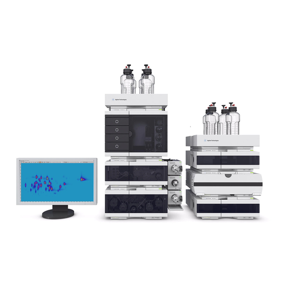
Figure 24 Left: Recommended stack configuration for the 1290 Infinity II 2D-LC System. Right: Bench space requirements of the 1290 Infinity II 2D-LC System. The dual stack configuration for 2D-LC requires at least 97 x 62 cm (24.4 x NOTE 38.2 inches) free, vertical bench space. - Page 61 Installation Hardware Installation Installation of the 2D-LC Valve and optional MHC decks Attaching the external valve drives For InfinityLab 2D-LC instruments that comprise at least one 1260 Infinity II or 1290 Infinity II pump, valve drives are attached to this pump with the Valve Clamp Kit IF II (5067-5685), while the valve drives are interconnected by the Adapter profile (5043-0269).
- Page 62 Installation Hardware Installation 1 Mount the clamp guide on the right side of the Infinity II Pump: Markings in the form of round dips are on the body housing. Make a small hole with a peaked screw driver and tighten the clamp guide with the 3 self-cutting tapping screws.
- Page 63 Installation Hardware Installation Valve Configurations Agilent InfinityLab 2D-LC Solutions offer two general valve configurations that decide which of the 2D-LC modes that can be used with the instrument. While the Single Heart-Cutting (SHC) configuration offers access to Single Heart-Cutting and Comprehensive 2D-LC, the Multiple Heart-Cutting (MHC) configurations additionally gives access to Multiple Heart-Cutting and High-Resolution Sampling 2D-LC.
- Page 64 Installation Hardware Installation Single Heart-Cutting Configuration 2D-LC instruments that are exclusively used for Single Heart-Cutting and Comprehensive 2D-LC experiments only require the standard 2D-LC valve (G4236A). The valve can be conveniently attached to any Infinity II pump that is installed. For a SHC configuration, transfer capillaries (6a/6b) are not necessary since MHC decks are not installed.
- Page 65 Installation Hardware Installation Multiple Heart-Cutting Configuration 2D-LC instruments that are used for Multiple Heart-Cutting or High-Resolution Sampling 2D-LC require additional MHC decks. For MHC configurations, both the standard 2D-LC valve (G4236A) and the ASM valve head (G4243A) are supported. The valves can be conveniently attached to any Infinity II pump in the stack.
- Page 66 Installation Hardware Installation Recommended Stack Setups InfinityLab 2D-LC Solutions allow three basic stack setups in three variations depending on the column compartment concept that is used. The pumps used for the first and second dimension distinguish the basic stack configurations. In the second dimension, a 1290 Infinity or 1290 Infinity II High-Speed Pump is mandatory.
- Page 67 Installation Hardware Installation Connecting the 2D-LC Valve, Standard (G4236A) The capillary connections of the 2D-LC valves depend on whether a con- or countercurrent configuration achieved. For the standard 2D-LC Valve, both concurrent and countercurrent operation is possible. Schematics in this chapter will reflect a concurrent direction.
- Page 68 Installation Hardware Installation Figure 29 Standard 2D-LC valve (G4236A) with MHC 1300 bar (counter current) 2D-LC User Guide...
- Page 69 Installation Hardware Installation Port Number of Connection L x ID [mm] Description Capillary transfer capillary to MHC Valve (OUT), deck 170 x 0.12 5500-1270 Capillary ST 0.12x170 S/M waste line self-cut x 0.7 0890-1713 Tubing-flexible 0.8/1.61mm PTFE WT (delivered with UV detector) 105 x 0.17 5500-1240...
- Page 70 Installation Hardware Installation Connecting the 2D-LC Valve, ASM (G4243A) In contrast to the standard 2D-LC Valve (G4236A) Agilent recommends using a counter-current configuration for the ASM 2D-LC Valve (G4243A) when working in ASM mode. This section describes the setup for a counter-current configuration of the ASM Valve.
- Page 71 Installation Hardware Installation Figure 30 Schematic representation of the ASM 2D-LC Valve (G4243A) in countercurrent flow. Against the example shown in the figure above, for 1200 bar MHC Valves that NOTE have a different symmetry, the connection is OUT/IN. 2D-LC User Guide...
- Page 72 Installation Hardware Installation Port Number of Connection L x ID [mm] Description Capillary waste line self-cut x 0.7 0890-1713 Tubing-flexible 0.8/1.61mm PTFE WT (delivered with UV detector) transfer capillary to MHC Valve (IN), deck A 170 x 0.12 5500-1376 Capillary ST 0.12x170 M/M transfer capillary from MHC Valve (OUT), 170 x 0.12 5500-1376...
- Page 73 Installation Hardware Installation Figure 31 Stack Setup #1. Recommended setup if both pumps are Infinity II modules or the pump is a 1290 Infinity Binary pump. Number of Connection L x ID [mm] P/N Description Capillary 400 x 0.17 5500-1245 Capillary ST 0.17x400 SI/SI D pump (top) to autosampler 600 x 0.12...
- Page 74 Installation Hardware Installation Figure 32 Stack Setup #2. Recommended setup if the D pump is a 1290 Infinity Binary Pump or a 1290 Infinity Quaternary Pump. Number of Connection L x ID [mm] P/N Description Capillary 600 x 0.17 5067-4670 Capillary ST 0.17x600 S/SH D pump (bottom) to sampler 600 x 0.12...
- Page 75 Installation Hardware Installation Figure 33 Stack Setup #3. Recommended setup if the D pump is a 1260 Infinity or 1260 Infinity II Binary Pump. Number of Connection L x ID [mm] P/N Description Capillary 900 x 0.17 5500-1217 Capillary ST 0.17x900 SI/SX D pump (bottom) to sampler 600 x 0.12 5067-4669...
- Page 76 Installation Hardware Installation Alternative instrument setups for additional functionality The standard stack setups can be upgraded with additional valves to add additional functionality. Table 8 on page 66 gives an overview of all supported modifications of a standard 2D-LC instrument. At a time, only one modification is recommended to ensure correct operation of the instrument.
- Page 77 Installation Hardware Installation Figure 34 Setup A. Recommended setup if a column switching valve (for example 6-position/14-port InfinityLab Quick-Change Valve) is used. For a InfinityLab 2-position/6-port Quick-Change Valve, adapters A1 are not necessary. Number of Connection L x ID [mm] Description Capillary Adapter: capillary 2 to column...
- Page 78 Installation Hardware Installation Figure 35 Setup B. Recommended setup if the instrument contains separate MCTs/ TCCs for D columns. Number of Connection L x ID [mm] Description Capillary 280 x 0.12 5067-4651 Capillary ST 0.12x280 D column to D DAD SL/SX 280 x 0.12 5067-4651...
- Page 79 Installation Hardware Installation Figure 36 Setup C. Recommended setup if D column is hosted in an Integrated Column Compartment (ICC). Number of Connection L x ID [mm] Description Capillary Injection Valve to ICC 0.12x105mm 5500-1238 Capillary ST 0.12x10⁵ SL/SL (provided with ICC) Heat exchanger out to column 0.12x280mm 5500-1170...
- Page 80 Installation Hardware Installation The driver-based 2D-LC Solution allows only certain valves to be configured as diverter valves which can be used for example as an effective desalting tool. A list of supported valves can be found in Table 8 on page 66 More information is available in the following sections: •...
- Page 81 Installation Hardware Installation Number of Connection L x ID [mm] Description Capillary 0.12 x 400 5067-4606 Capillary ST 400x0.12 S/SH Capillary from D detector to T-piece T-piece 0100-0969 1/16in Tee, SST, Low Dead Volume Capillary from MS to T-piece (self cut) 0.12 x 400 0890-1915 Capillary PEEK, 0.12x1250...
- Page 82 Installation Hardware Installation Figure 38 Setup E. Recommended setup for the D switching valve. Number of Connection L x ID [mm] Description Capillary 400 x 0.12 5500-1251 Capillary ST 0.12x400 SL/SL MCT / TCC to D DAD 280 x 0.12 5067-4651 Capillary ST 0.12x280 D MCT / TCC to...
- Page 83 Installation Hardware Installation Figure 39 Setup F. Recommended setup for the D switching valve without D detector. Number of Connection L x ID [mm] Description Capillary 280 x 0.12 5067-4651 Capillary ST 0.12x280 D Switching Valve (2) to D DAD SL/SX 120 x 0.12 5067-4652...
- Page 84 Installation Hardware Installation Figure 40 Setup G. Single Heart-Cutting Configuration as Single Sample Loop Setup Number of Connection ID x L [mm] Description Capillary Bypass capillary (OUT) 0.12 x 10⁵ 5500-1238 Capillary, ST 0.12x10⁵ SL/SL Waste line self-cut x 0.7 0890-1713 Tubing-flexible 0.8/1.61mm PTFE WT (delivered with UV detector)
- Page 85 Installation Hardware Installation Installing the Pressure Release Kit From DAD cell out T-piece 5500-1245 Capillary ST 0.17x400 SI/SI 5500-1240 Capillary ST 0.17x10⁵ SL/SL 5500-1227 Capillary ST 0.17x150 SL/SL To damper capillary To 2D-LC valve (Valve port 3) Figure 41 Connections to the pressure release kit Parts required Description G4236-60010...
- Page 86 Installation Hardware Installation Insert the pressure release assembly to the leak tray, Push the pressure release assembly in the correct orientation as shown. position. to waste to T-piece (inline with the detector) Connect with the T-piece, see Figure 41 on page 85. Install the Valve Head and Connecting Capillaries For instructions on how to install the valve head and connecting capillaries, see “Replace Valve Heads (G1170A)”...
-
Page 87: Licensing The 2D-Lc Instrument
Installation Hardware Installation Licensing the 2D-LC Instrument To use the driver-based 2D-LC solution, you need different licenses depending on the chromatography data system (CDS) you are using. For further details please refer to the CDS documentation. In general, however, the following applies: •... - Page 88 Hardware Installation Activate the 2D-LC System Driver With a Dongle-Based License When you purchase Agilent 1290 Infinity II 2D-LC Solution from Agilent you will receive a single USB stick which includes the 2D-LC dongle license. To run the system and use its functionality, the D pump must be activated.
-
Page 89: Software Installation
Installation Software Installation Software Installation 2D-LC Software Installation in Agilent Masshunter Workstation A compatible CDS must be installed first. For details, see the CDS Prerequisites documentation. To observe if your computer full fills the requirements, like for the hardware CPU, memory, hard disk space and the software, check the windows settings. - Page 90 Installation Software Installation 5 Install Service Packs for Data Acquisition. 6 Install Quantitative Analysis Reporting. [OPTIONAL] 7 Configure Excel for MassHunter. This configuration is mandatory to avoid any issues later. Usually, the CDS NOTE installs a driver, which however may not be the latest one and may require a driver update in the next step.
- Page 91 Installation Software Installation • MassHunter Workstation Data Acquisition eFamiliarization Guide Use this interactive online guide to get to know the Data Acquisition program. • MassHunter Qualitative Analysis eFamiliarization Use this interactive online guide to learn to use the Qualitative Analysis programs.
- Page 92 Installation Software Installation Online Help • To get more information about a window or dialog box, place the cursor on the window or dialog box of interest and press F1. • In the Agilent MassHunter IM-MS Browser program, you instead click Help > Contents.
-
Page 93: Lc Software Configuration Agilent Masshunter Workstation
Installation Software Installation 2D-LC Software Configuration Agilent MassHunter Workstation Start the Configuration Dialog The 2D-LC hardware is correctly set up and the system configuration, the project Prerequisites settings and the most instrument settings like the IP Addresses are already defined. 1 Open the Control Panel. - Page 94 Installation Software Installation 4 To configure the instrument, use the Instrument Configuration dialog: [OPTIONAL] a To change the name of the instrument, type a new Instrument name. b To configure the LC instrument, click Device Config..Figure 43 MassHunter Instrument Configuration window The Auto Configuration dialog opens.
- Page 95 Installation Software Installation Configure the HPLC Instrument D Pump Figure 44 Auto Configuration window of a full 2D-LC solution with two MHC valves and a diverter valve 1 Check/Select 2D-LC System in Cluster Options. 2 Uncheck the D pump in Available Modules. 3 To create a cluster, click the Create Cluster button.
- Page 96 Installation Software Installation Configure the 2D-LC Cluster Figure 45 2D-LC Cluster Configuration (for an ASM Valve, MHC Valves and a Diverter Valve) The 2D-LC software configuration window allows the following: • Verification of the D and D pump configuration • Configure D pump •...
- Page 97 Installation Software Installation [OPTIONAL] 1 To change the Device Name, connection settings and the Pressure Units, fill in the according fields. 2 To verify the correct D and 2D pump configuration, check the Pumps settings. This action will not rename your pumps. Enter a descriptive naming during initial NOTE instrument setup in the instrument configuration, see “Configure the HPLC...
- Page 98 Installation Software Installation Not all detectors to be configured will automatically appear in the configuration NOTE window. If you want to configure more detectors, you have to do it manually using the add-on button. Please note the following notation first the module number followed by a colon and then the serial number, for example G6135C: US12345678.
- Page 99 Installation Software Installation Configure the Device UI 1 Define names of modules (device name). Possible options are, for example, the following: • Sampler • Iso Pump • D Bin Pump • D MCT, • D MCT, • D DAD, • D DAD, For an example, see Figure 46...
- Page 100 Installation Software Installation Figure 46 Naming in the Device Configuration for the D detector Figure 47 Arrangement of the module UI in the dashboard 2D-LC User Guide...
- Page 101 Installation Software Installation 3 To improve the data rate for each detector, it is recommended to connect both, D and D, detectors to the LAN. To configure the second detector for the LAN communication, you have to select the detector in the UI and click Additional connection..
- Page 102 Installation Software Installation 5 If instrument is configured successfully, click OK. Figure 49 Successful Instrument Configuration of a 2D-LC Q-TOF instrument If you want to change the 2D-LC cluster configuration later, right click in 2D-LC UI NOTE in the dashboard of the CDS. 2D-LC User Guide...
- Page 103 2D-LC Data Acquisition in MassHunter Workstation 11 Start the Data Acquisition Software Overview 2D-LC in MassHunter Acquisition 11 Instrument Status 2D-LC User Interface Additional Information in the 2D-LC User Interface 2D-LC Valves Online Monitor in the 2D-LC User Interface Method Editor Window Sample Run Window Worklist Window Tune Window...
-
Page 104: Lc Data Acquisition In Masshunter Workstation
2D-LC Data Acquisition in MassHunter Workstation 11 Start the Data Acquisition Software Start the Data Acquisition Software Preparations To start your instrument, you need the following: • A configured instrument • A CDS project associated to the instrument • Permission to Run Instrument included with Instrument User, Instrument Administrator, or Everything role (if authentication is selected) 1 To start the data acquisition, double-click the MassHunter 2DLC QTOF (online) icon. - Page 105 2D-LC Data Acquisition in MassHunter Workstation 11 Start the Data Acquisition Software You do almost all of your work within the different windows of this main window. These windows provide tools to do the following: • Set up acquisition methods •...
-
Page 106: Overview 2D-Lc In Masshunter Acquisition 11
2D-LC Data Acquisition in MassHunter Workstation 11 Overview 2D-LC in MassHunter Acquisition 11 Overview 2D-LC in MassHunter Acquisition 11 The dashboard is the common UI element for instrument control. The driver is responsible for hardware-related features plugged in to the CDS software. -
Page 107: Instrument Status
2D-LC Data Acquisition in MassHunter Workstation 11 Instrument Status Instrument Status The Instrument Status window shows the status of each device configured with the instrument. The possible values for Status are shown in the following figure. You also set nonmethod control and configuration parameters for the LC devices and the MS instrument. -
Page 108: 2D-Lc User Interface
2D-LC Data Acquisition in MassHunter Workstation 11 2D-LC User Interface 2D-LC User Interface The instrument status window shows the current state of each of the device. The 2D-LC device is in this example not ready. You can click the button in any device pane to get help on that device. - Page 109 2D-LC Data Acquisition in MassHunter Workstation 11 2D-LC User Interface Figure 55 Full view of the 2D-LC UI Flow The current solvent flow rate (in mL/min). Pressure The current pump pressure (in bar, psi or MPa) Pressure Limit The current maximum pressure limit. Composition A:B The current solvent composition.
- Page 110 2D-LC Data Acquisition in MassHunter Workstation 11 2D-LC User Interface Further information and setting options are available in the Context Menu. For example, you have access to module control and capillaries settings in modify. To make the context menu visible, you have to right click in the UI. In this view, there are several hardware-related features available like the following: Figure 56 Context Menu / Control Interface of the 2D-LC Cluster...
- Page 111 2D-LC Data Acquisition in MassHunter Workstation 11 2D-LC User Interface Prepare Pump Allows you to control the Purge, Condition, or the Prime function. • Purge: Purge the LC pump. Fill the system with fresh or different solvent. Follow the directions for purging the pump in the user guide for your pump.
- Page 112 2D-LC Data Acquisition in MassHunter Workstation 11 2D-LC User Interface Figure 57 Modify capillaries windows allows the configuration of the sample loop, transfer capillaries, and ASM capillaries Modify Transfer Volumes Displays the Modify Transfer Volumes dialog box. In this window, you can configure the transfer volumes for the D detector and the D detector.
- Page 113 2D-LC Data Acquisition in MassHunter Workstation 11 2D-LC User Interface Transfer Volume D detector D settings for the transfer volumes that determine the time between the detection of the peak and the switching of the 2D-LC valve, depend on the hardware setup.
-
Page 114: Lc Valves Online Monitor In The 2D-Lc User Interface
2D-LC Data Acquisition in MassHunter Workstation 11 2D-LC Valves Online Monitor in the 2D-LC User Interface 2D-LC Valves Online Monitor in the 2D-LC User Interface The Online Monitor displays the status of the 2D-LC valve. The following illustrations show some examples so that you can see what is happening at any time during operation. - Page 115 2D-LC Data Acquisition in MassHunter Workstation 11 2D-LC Valves Online Monitor in the 2D-LC User Interface Figure 62 Flush indicated by red beam moving along Figure 63 Hovering over analysis loop indicates time passed and time remaining (in seconds) Figure 64 HiRes series give the same parking time (here cuts 3 and 4, and 6 and 7) 2D-LC User Guide...
-
Page 116: Method Editor Window
2D-LC Data Acquisition in MassHunter Workstation 11 Method Editor Window Method Editor Window In the Method Editor window, you enter acquisition parameters for the method, “Method Parameters” on page 125. To decouple the Method Editor from UI, double click the Method Editor bar. Then NOTE you can enlarge the window to get a full screen view for programming. -
Page 117: Sample Run Window
2D-LC Data Acquisition in MassHunter Workstation 11 Sample Run Window Sample Run Window In the sample run window, you enter sample information to run individual samples interactively, and you can start a single sample run. 2D-LC User Guide... -
Page 118: Worklist Window
2D-LC Data Acquisition in MassHunter Workstation 11 Worklist Window Worklist Window With the worklist window, you enter sample information for multiple samples. When you run the worklist, the samples are automatically run in the order listed in the worklist. You can add one or more tune actions to the Worklist when you add a factory script to the worklist. -
Page 119: Tune Window
2D-LC Data Acquisition in MassHunter Workstation 11 Tune Window Tune Window In the Tune window, you tune the mass spectrometer. You can use one of the automated tuning algorithms, or you can manually tune the instrument. Manual tuning can result in a less than optimal tune; however, if you perform a manual tune, Agilent recommends that you only manually tune the front part of the instrument: ion source and optics 1. -
Page 120: Instrument Details
2D-LC Data Acquisition in MassHunter Workstation 11 Instrument Details Instrument Details In some case, it may be necessary to check the various details such as the firmware and driver version. The following options to obtain this information exist: • “Use Module List to Obtain Instrument Details” on page 120 •... -
Page 121: Use Instrument Configuration Report To Obtain Instrument Details
2D-LC Data Acquisition in MassHunter Workstation 11 Instrument Details Use Instrument Configuration Report to Obtain Instrument Details 1 Start the Data Acquisition program. 2 Select the Instrument Configuration from the Print Reports layout. 2D-LC User Guide... - Page 122 2D-LC Data Acquisition in MassHunter Workstation 11 Instrument Details 3 Click Screen. 4 Click OK. 2D-LC User Guide...
-
Page 123: Log Book In Masshunter Acquisition 11
2D-LC Data Acquisition in MassHunter Workstation 11 Log book in MassHunter Acquisition 11 Log book in MassHunter Acquisition 11 Sometimes it is necessary to check the processes that take place in a InfinityLab LC/MSD instrument. Therefore, there is a log file in which the processes are logged. - Page 124 2D-LC Data Acquisition in MassHunter Workstation 11 Log book in MassHunter Acquisition 11 Configure logbook notification If you get more logbook notifications than is useful to you, you can change the type of notifications that are displayed. 1 Click on Filters in the taskbar. 2 Select the type of notifications that you want displayed.
-
Page 125: Method Parameters
Multi-Inject Dynamic Peak Parking This chapter provides background information on method parameters. It helps to optimize methods in Agilent 1290 Infinity II 2D-LC Solution in the modes standard heart-cutting, multiple heart-cutting, high resolution sampling and comprehensive 2D-LC. 2D-LC User Guide... -
Page 126: Method Editor 2D-Lc
Method Parameters Method Editor 2D-LC Method Editor 2D-LC The method setup dialog is used to edit the 2D-LC specific method parameters. Figure 66 2D-LC method setup The setup of following method parameters is available: • 2D-LC Operation Mode, see “2D LC Operation Mode” on page 127 •... -
Page 127: Set The 2D-Lc Method Parameters
Method Parameters Set the 2D-LC Method parameters Set the 2D-LC Method parameters 2D LC Operation Mode Setting the mode has the following consequences: Heart-Cutting (LC-LC) The Heart-Cutting mode covers two 2D-LC applications Heart Cutting (LC-LC) and High-Resolution Sampling (HiRes). Once you have selected the Heart-Cutting mode, you can later define in the software whether you want to use one or the other mode or even both together. - Page 128 Method Parameters Set the 2D-LC Method parameters Comprehensive 2D-LC (LC*LC) If you have selected comprehensive 2D-LC, the entire volume of the D will be injected (using the D pump) onto the D column. Two identical loops are used alternating, while one loop is filled in D, the volume of the other loop is separated with the D column.
-
Page 129: Define The 1D Pump Flow
Method Parameters Set the 2D-LC Method parameters Define the D Pump FLow 1 Set the D Pump Flow (range 0 – 5.0 mL/min). This setting defines the flow in the first dimension being used while 2D-LC is active. Any changes of the Flow parameter in the 2D-LC UI are automatically synchronized with the Method User Interface of the D pump. -
Page 130: Define The 2D Solvent
Method Parameters Set the 2D-LC Method parameters Define the D Solvent 1 Set the percentage of solvent B to any value from 0 – 100 % in steps of 0.01 %. Figure 69 2D-LC solvent settings Solvent A always delivers the remaining percentage of volume. If the rate of solvent B is, for example, set to 20 %, solvent A, following the calculation %A = 100 - %B, automatically is set to 80 %. - Page 131 Method Parameters Set the 2D-LC Method parameters D pump is the stop time master for the complete 2D-LC system. The stop NOTE times of all other modules in the system must be set to As Pump/ As Injector except the D pump module that should set the Stop Time Modus As Injector/No Limit.
-
Page 132: Define The Posttime
Method Parameters Set the 2D-LC Method parameters Define the Posttime To allow your column to equilibrate after changes in solvent composition (for example after gradient elution), use the post time. The instrument remains in a post-run state during the post time to delay the start of the next analysis. -
Page 133: Edit The Sampling Table
Method Parameters Set the 2D-LC Method parameters Edit the Sampling Table The content of the sampling table specifies when (within the runtime of the first dimension) the selected 2D-LC mode is active. 1 To manually define and edit the sampling table, click one of the buttons: •... - Page 134 Method Parameters Set the 2D-LC Method parameters Table 10 Sampling table description Type Description Time Defines the start time of the cut. Function Defines the mode of sampling. To select an alternative mode, click the down-arrow: • Time-Based Heart-Cuting Define a time-based Heart-cutting run (MHC or HiRes) in the sampling table.
- Page 135 Method Parameters Set the 2D-LC Method parameters Define Parameters for Peak-Based Heart Cut 1 To switch between Multiple Heart-Cutting (MHC) and High Resolution Sampling peak-based (HiRes), click the down-arrow. Sampling time The sampling time is the maximal Cut size in seconds (t) in case no peak end is detected by the (MHC) peak detector.
- Page 136 Method Parameters Set the 2D-LC Method parameters Define Parameters for Time-Based Heart Cut 1 To switch between Multiple Heart-Cutting (MHC) and High Resolution Sampling (HiRes), click the down-arrow. Figure 74 Parameter window in the sampling table for High Resolution Sampling (HiRes) settings and Multiple Heart-Cutting Settings (MHC) NOTE if you use the optimization function in the reference chromatogram the analyze mode in the...
- Page 137 Method Parameters Set the 2D-LC Method parameters 2 To choose an analyze mode, click the down-arrow from the drop-down list. • Selecting default: The cut is analyzed as soon as possible. • Selecting Delayed: Analysis is delayed until there is an available time slot. •...
- Page 138 Method Parameters Set the 2D-LC Method parameters Define Parameters for Time-Based Comprehensive Parameters for Time-Based Comprehensive Figure 75 Comprehensive preview with a modulation time 0.3 min (=20 cycles) 1 Enter an absolute time range where the system creates equidistant cuts. Comprehensive run starts at the given time.
-
Page 139: Define The 2D Gradient
Method Parameters Set the 2D-LC Method parameters Define the D Gradient The 2D Gradient window summarizes all the important settings needed to optimize the gradient method for a second dimension run. Specify the Gradient Phase 1 Specify the duration (in minutes) of the D run for a single cut in the Analysis field. - Page 140 Method Parameters Set the 2D-LC Method parameters Use Loop Flushing and Active Solvent Modulation (ASM) If your 2D-LC instrument is equipped with the G4236A 2D-LC ASM Valve, this method development feature helps finding the optimal dilution of D solvents in the sample loop.
- Page 141 Method Parameters Set the 2D-LC Method parameters 2 Specify the number of times to flush the sample loop in the Flush Sample Loop field. Flushing the sample loop three times is typically enough and the recommended NOTE default. Less time may be sufficient and can be verified during optimization. The user interface displays how long the flushing will take.
- Page 142 Method Parameters Set the 2D-LC Method parameters Modulation The Modulation section shows the 2D-LC Cycle/Modulation time, which is the sum of the analysis time and the equilibration time specified in the Gradient Phases section. The modulation time also depends on the sample loop built into the instrument, see “Recommendations for Instrument Setup”...
- Page 143 Method Parameters Set the 2D-LC Method parameters Specify the Switch Time of the Diverter Valve The diverter valve can be used to automatically divert salt or buffers coming from D mobile phase to waste at the beginning of every D analysis. This section is active only if a diverter valve is included in the 2D-LC Cluster configuration.
- Page 144 Method Parameters Set the 2D-LC Method parameters 4 To manually define and edit the Analytical Gradient, click one of the following buttons: • • Remove • Clear All • • Copy • Paste Clicking, e.g., the Add button, generates a single analytical gradient event, where you can define the time for the change and the solvent composition.
- Page 145 Method Parameters Set the 2D-LC Method parameters Modify the Solvent Composition in the D gradient Over the Run Time of Use this section to modify the solvent composition in the D gradient over the run time of the first dimension. For each setpoint in the Analytical Gradient table that is marked in the Shift column, you can set up a gradient shift as a nested gradient.
- Page 146 Method Parameters Set the 2D-LC Method parameters 4 To manually define and edit the shifted D gradient, click one of the following buttons: • • Remove • Clear All • • Copy • Paste Clicking, e.g., the Add button, generates a single gradient shift event, where you can define the time for the change and the solvent composition.
-
Page 147: Use The Flush Gradient
Method Parameters Set the 2D-LC Method parameters Use the Flush Gradient The Flush Gradient can be used to flush the transfer capillaries and Sample Loops. You can choose to use the analytical gradient or you can set up a custom flush gradient. -
Page 148: Use Peak Trigger
Method Parameters Set the 2D-LC Method parameters Use Peak Trigger Set Peak Trigger in Time-Based Mode If the Use check box is selected, the peak detection settings are used for finding and marking D peaks within the reference chromatogram in the preview UI. This means that first a known D reference chromatogram of the instrument must be loaded and then can be used to detect the correct position of sample peaks for a... - Page 149 Method Parameters Set the 2D-LC Method parameters 4 Select Threshold, Slope or Threshold and Slope from the Peak detection mode drop-down list. [OPTIONAL] a Set Threshold. In Threshold mode, the 2D-LC Valve is triggered on the threshold of the detector signal. The threshold value is given as mAU value. When the UV signal rises above this value, with a certain delay the 2D-LC Valve is triggered and switches to cut the fraction.
- Page 150 Method Parameters Set the 2D-LC Method parameters [OPTIONAL] c Or set Threshold and Slope. In Threshold and Slope mode, the 2D-LC cutting (peak parking) is triggered when the corresponding values for threshold and slope are reached. If the detector signal exceeds both the threshold and the Up Slope value, the cutting of the fraction is started.
- Page 151 Method Parameters Set the 2D-LC Method parameters • Down Slope This method detects peaks based on down slope values only. The slope of the falling peak triggers the peak cutting. The slope value is based on the first derivative of the signal. The default value is 1.00 mAu/s. •...
-
Page 152: Use The Advanced 2D Pump Settings
Method Parameters Set the 2D-LC Method parameters Use the Advanced D Pump Settings Advanced settings open the pump method viewlet for Advanced D pump settings. Use the table to set up the additional D pump parameters: 1 Set the Maximum Flow Gradient. You can set a limit on the rate of change of the solvent flow to protect your analytical column. - Page 153 Method Parameters Set the 2D-LC Method parameters [OPTIONAL] 3 Set the maximum and minimum Pressure Limits for the pump. The default settings are recommended. Change these settings only for important NOTE and valid reasons. • Max is the maximum pressure limit at which the pump will switch itself off. This maximum pressure limit protects the system against overpressure.
-
Page 154: Preview (2D-Lc)
Method Parameters Preview (2D-LC) Preview (2D-LC) The Preview panel shows loaded reference chromatogram and the 2D-LC gradient profiles in one or two windows: • The main window, which is always visible, can show the detector signal of the reference chromatogram and the D gradient profile over the whole run. - Page 155 Method Parameters Preview (2D-LC) Displays a data file selection box that allows you in the next steps to select a D data file. Figure 78 Selection drop-down menu to select shift volume or shift time 2D-LC User Guide...
- Page 156 Method Parameters Preview (2D-LC) Finally loaded the data file that can be used to display a D reference chromatogram in the Preview. Uploading a reference signal into the method screen can be helpful to illustrate, at which positions of the chromatogram which cuts will be taken. Figure 79 Loaded D chromatogram in preview window...
- Page 157 Method Parameters Preview (2D-LC) Figure 80 Example of a loaded Q-TOF signal with shift volume set to 0 µL compared Q-TOF signal with shift volume set to -100 µL This tool removes the current reference chromatogram from the Preview. This tool switches to Multiple Heart-Cutting mode (MHC). This tool can only be used if heart-cutting is selected in the 2D-LC Operation mode.
- Page 158 Method Parameters Preview (2D-LC) Using this tool, depending which mode MHC or HiRes is selected, will automatically sample the entire chromatogram using the current Peak Trigger parameters and enters all detected cuts into the Sampling Table. This tool can only be used if the use box in the peak trigger section is checked.
- Page 159 Method Parameters Preview (2D-LC) If still some peaks cannot be parked, user can define important peaks (Prioritize) in the sampling table. Figure 81 2D run optimization done all peaks (blue) are analyzed compared to Figure OOXXX without optimization below This tool resets the current optimization, disables smart parking, but it will keep the run time extension.
- Page 160 Method Parameters Preview (2D-LC) Figure 82 Preview of the display of the analytical D gradient in purple and the flush in orange If the D gradient view is activated in the main window, the Y-axis shows %B. NOTE 2D-LC User Guide...
- Page 161 Method Parameters Preview (2D-LC) This tool toggles the display of the threshold and slope values at the cursor position in the Preview. This tool can only be used if the gradient preview in the main panel is deactivated. For manually changing the threshold setting in the preview, see ... Using this tool will toggle the display of the D analytical gradient panel at the right of the Preview.
-
Page 162: Further Graphical Explanation
Method Parameters Preview (2D-LC) Further Graphical Explanation Further Graphical Explanation of the 2D-LC Preview Window: The grey triangle illustrates which peaks the peak trigger settings detect in the reference chromatogram. To add or remove the cut, double-click the grey triangles in the preview. The grey line in the preview marks the stop time. - Page 163 Method Parameters Preview (2D-LC) Figure 83 Chromatogram with missed peaks marked red MHC cuts This function uses the continuous flow-through principle. The cuts are visualized as light green bars. The (time based) dark line on the right edge of the bar indicates the switching time of the 2D-LC valve and the end of parking the peak.
- Page 164 Method Parameters Preview (2D-LC) MHC cuts / MHC cuts / HiRes cuts (peak-based) are displayed graphically in blue bars. HiRes cuts Hovering over the bars gives you the option to move the HiRes Sampling. (peak-based) Move cut You can: • Increase or decrease the cut size •...
- Page 165 Method Parameters Preview (2D-LC) Resize the Hovering over the bars gives you the option to increase or decrease the cut series (indicated by green HiRes series highlights). You can resize by: • Clicking the highlighted series and dragging the edge along •...
- Page 166 Method Parameters Preview (2D-LC) Hovering over highlight bars give you more cut information, like cut number, start and end time of the cut and Information in which deck and loop the cut is parked. Also D gradient / i.e. time of analysis is indicated. Setup The initial D gradient in the Analytical Gradient preview by double click purple line adds a purple ball, which...
- Page 167 Method Parameters Preview (2D-LC) Activate the D gradient view will display the name of the Y-axis in %B. If the threshold is activated, you can grab this line and shift up and down to adjust the threshold. This measure will also update Peak Trigger settings. If you hover over the threshold line, the slope is also displayed at the intersection with the peak signal.
-
Page 168: Set Up A Peak-Based Experiment Graphically
Method Parameters Set up a Peak-Based Experiment Graphically Set up a Peak-Based Experiment Graphically Figure 84 Peak-based experiment based on a prediction In peak-based mode, the D detector triggers sampling/parking of cuts in dependence on a UV-threshold (or slope) A peak appears in the detector, the threshold is reached (= peak start), the 2D-LC modulator starts sampling. - Page 169 Method Parameters Set up a Peak-Based Experiment Graphically 3 Select Detector and Signal used for triggering. In this example G7117A and Signal A are selected. 4 Select MHC or HiRes. The icon corresponds to the peak-based operation. In this example HiRes is selected.
- Page 170 Method Parameters Set up a Peak-Based Experiment Graphically Figure 85 Two selected peaks in peak based mode and corresponding peak-based sampling table To generate a peak based event in the preview, you can also use the add icon or NOTE do a right click somewhere into the preview, and press add cut.
- Page 171 Method Parameters Set up a Peak-Based Experiment Graphically 6 If some highlights appear in red hovering over the warning triangle tells you that stop time must be adjusted. To adjust the stop time the stoptime button must be clicked pressed. Then the Stop time has been prolonged to ensure that all predicted cuts can be D analyzed.
- Page 172 Method Parameters Set up a Peak-Based Experiment Graphically Figure 88 Example shows result of displayed in the MassHunter Qual 1D-Chromatogram + Cut markers This example is based on a prediction. For experiments with unknown outcome NOTE you have to add an extra time to the stop time for cases where you don't know what to expect.
-
Page 173: Setup 2D Gradient Graphically
Method Parameters Setup 2D Gradient Graphically Setup D Gradient Graphically 1 Load the initial D gradient in the Analytical Gradient Preview. 2 To change the initial gradient, double click on the purple line. Figure 89 Analytical gradient This adds a gradient point to the line (purple point). This gradient point can be moved. - Page 174 Method Parameters Setup 2D Gradient Graphically 4 Click This activates the threshold line. To adjust the threshold, grab this line and shift up or down. This will update the peak trigger settings. If you hover over the threshold line, the slope is also displayed at the intersection with the peak signal.
-
Page 175: Setup Second Dimension Gradient With The Graphical User Interface
Method Parameters Setup Second Dimension Gradient with the Graphical User Interface Setup Second Dimension Gradient with the Graphical User Interface The user can graphically set up the D gradient including the initial composition (%B) value, the D stop time, and the modulation (repetition) time. Analytical You can change or adjust the values of the Analytical Gradient graphically. - Page 176 Method Parameters Setup Second Dimension Gradient with the Graphical User Interface More Hovering over cycle time and or time for ASM flush-out displays actual time in second: Three digits (for Modulation comprehensive mode). Information More Info Hovering over analysis loop indicates time passed and time remaining (in seconds) More info about online, 2D-LC Valve “2D-LC Valves Online Monitor in the 2D-LC User Interface”...
-
Page 177: Additional Information
Method Parameters Additional Information Additional Information Multi-Inject To sample a broad 1D-region that does not fit into currently installed sampling loops (e.g. 40 µL volume) HiRes is the method of choice. Take in account, that this leads to an increased number of D cycles. - Page 178 Method Parameters Additional Information Figure 93 Example of High Resolution sampling (5 cuts) with 5 analytical gradients Figure 94 Example of High Resolution sampling (5 cuts) with only one analytical gradient for all cuts Multi-Inject works similar to an injection from a large sample loop. Large NOTE injection volumes can negatively affect D separation.
-
Page 179: Dynamic Peak Parking
Method Parameters Additional Information Dynamic Peak Parking In certain cases, small variations of parameters can influence changes in the retention time (RT) mechanism. This can happen, for example, with certain types of analytes such as peptides. As a solution to compensate for such effects in Time-based (M)HC 2D-LC experiments, the Dynamic Peak Parking is used. - Page 180 Method Parameters Additional Information 5 Verify in the sampling table the expected time for the IRTS, which corresponds to the peak-start trigger in the preview (intersection of threshold line and peak front). Then define the Reference Index value for IRTS, which is then shown in sampling table.
- Page 181 Method Parameters Additional Information 6 If a Reference Index has been defined for the IRTS, then all following time-based cuts automatically get the Reference Index value and are so linked to IRTS with this index. Figure 97 Time based cut with Reference Index 1 and Reference Factor 2 The Reference Factor can be setup up for the case where RT shifts are not linear (e.g.
- Page 182 Method Parameters Additional Information Example of a Dynamic Peak Parking Setup Figure 98 Example picture of the dynamic cut shift setup Table 11 IRTS Peak-based start: 2.10 min Peak-based end: 2.80 min Expected time: 2.67 min The maximum shift of the IRTS is 0.57 min. This means the end of peak-based area is at 2.80 min and the next time-based cut with reference to IRTS can be placed at 2.8 + 0.57 = 3.37 min.
- Page 183 Method Parameters Additional Information Figure 99 Shift of IRTS (2.686 min) to earlier RT (2.234 min) which is compensated by the system Figure 100 Shift of IRTS (2.235 min) to later RT (2.686 min) which is compensated by the system 2D-LC User Guide...
- Page 184 Method Parameters Additional Information Modulation Hovering over Cycle time and or time for ASM flush-out displays Information actual time in second: 3 digits (for comprehensive mode) Figure 101 Modulation 2D-LC Valve Hovering over analysis loop indicates time passed and time Online monitoring remaining (in seconds).
-
Page 185: Method Development Of Active Solvent Modulation (Asm)
Method Development of Active Solvent Modulation (ASM) Method Development of Active Solvent Modulation (ASM) Method Parameters Optimize the Dilution by Using ASM Capillaries Optimize the Sample Loop Flush Include the ASM Phase to the 2D Gradient Optimize Dilution Through Method Settings This chapter provides information on how to develop methods when using Active Solvent Modulation (ASM). -
Page 186: Method Development Of Active Solvent Modulation (Asm)
Method Development of Active Solvent Modulation (ASM) Method Development of Active Solvent Modulation (ASM) Method Development of Active Solvent Modulation (ASM) ASM method development helps finding the optimal dilution of 1D solvents in the sample loop for best 2D resolution at lowest cycle time. After switching on the ASM functionality (see “Method Parameters”... -
Page 187: Method Parameters
Method Development of Active Solvent Modulation (ASM) Method Parameters Method Parameters Advanced settings of 2D-LC method parameters allow switching on and off the use of the ASM functionality. • If this option is off, it works as a standard 2D-LC valve without dilution. •... -
Page 188: Optimize The Dilution By Using Asm Capillaries
Method Development of Active Solvent Modulation (ASM) Optimize the Dilution by Using ASM Capillaries Optimize the Dilution by Using ASM Capillaries A choice of four different ASM capillaries is available for achieving best results. Longer capillaries reduce, shorter capillaries increase the dilution of 1D solvent in the sample loop. -
Page 189: Optimize The Sample Loop Flush
Method Development of Active Solvent Modulation (ASM) Optimize the Sample Loop Flush Optimize the Sample Loop Flush Activate ASM in the software and set Flush sample loop to 3.0 times. Flushing the sample loop 3 times is typically enough and the recommended NOTE default. -
Page 190: Include The Asm Phase To The 2D Gradient
Method Development of Active Solvent Modulation (ASM) Include the ASM Phase to the 2D Gradient Include the ASM Phase to the D Gradient Figure 103 Programming the D gradient table (example) The dilution during the ASM phase takes time. That's why the ASM phase shifts the analytical gradient start. -
Page 191: Optimize Dilution Through Method Settings
Method Development of Active Solvent Modulation (ASM) Optimize Dilution Through Method Settings Optimize Dilution Through Method Settings Figure 104 Optimizing separation using a lower percentage of B for the ASM and column equilibration phase (example) For optimizing separation, you may use a lower percentage of B for the ASM phase and column equilibration phase compared to the original gradient for increasing dilution before the D column. -
Page 192: Run The System
Run the Checkout Familiarization Procedure for ASM Multiple Heart-Cutting (MHC) Run the Checkout Familiarization Procedure for ASM Comprehensive This chapter describes how to run the Agilent 1290 Infinity II 2D-LC Solution in the modes standard heart-cutting, multiple heart-cutting, high resolution sampling and comprehensive 2D-LC with the driver-based 2D-LC Solution. -
Page 193: Familiarization To Start A System Run
With the given method, peaks will overlap in the first dimension and will be separated in the second dimension. The Agilent 1290 Infinity II 2D-LC Solution is delivered together with all required parts for a complete familiarization procedure for (multiple) heart-cutting and comprehensive 2D-LC. -
Page 194: Prepare The 2D-Lc System
Run the System Prepare the 2D-LC System Prepare the 2D-LC System Prepare the 2D-LC System for LC As a user guide for good preparation, refer to the help instruction and suggestions of Good Laboratory Practice for HPLC. 1 Condition your Agilent HPLC instrument to have a stable system. 2 For further details, see Best Practices for Using an Agilent LC System (SD-29000194 Rev. -
Page 195: Configure The 2D-Lc System
Run the System Configure the 2D-LC System Configure the 2D-LC System The familiarization refers to the driver-based 2D-LC solution. The 2D-LC software Prerequisites requires at least the following CDS versions: • MassHunter 11 • OpenLab 2.6 For further details like firmware and driver, see “Compatibility Matrix”... - Page 196 Run the System Configure the 2D-LC System Configure 2D-LC Hardware Focus on the 2D-LC Valves and the capillary connection. 1 To find out the correct plumbing of the 2D-LC valve ports, see “Connecting the 2D-LC Valve, Standard (G4236A)” on page 67, “Connecting the 2D-LC Valve, ASM (G4243A)”...
- Page 197 Run the System Configure the 2D-LC System Configure 2D-LC Software 1 Configure the 2D-LC solution as 2D-LC Cluster, see “Configure the 2D-LC Cluster” on page 96. 2 To check the correct selection of the individual components like sample loop, transfer capillary and ASM capillary (if applicable), use the context menu function Modify.
-
Page 198: Checkout Familiarization Procedure
Run the System Checkout Familiarization Procedure Checkout Familiarization Procedure The checkout familiarization procedure requires 2D-LC starter sample, 1 x 2 mL (5190-6895), that contains the following components. Table 13 Components of 5190-6895 Analyte CAS# Atrazine 001912-24-9 Atrazine-desethyl 006190-65-4 Chlorotoluron 015545-48-9 Diuron 000330-54-1 Hexazinone... -
Page 199: Prepare The Experiment
Run the System Prepare the Experiment Prepare the Experiment Parts required Description 5190-6895 2D-LC starter sample, 1 x 2 mL G2453-85060 Formic Acid-Reagent Grade 5 mL (5 cc) 858700-902 RRHD SB-C18, 2.1x100 mm, 1.8 µm, 1200 bar 857768-901 RRHD Bonus-RP, 2.1x50 mm, 1.8 µm, 1200 bar D for Heart Cutting (LC-LC) and High Resolution (High Res) 959757-302 RRHD Eclipse Plus C18, 3.0x50 mm, 1.8 µm... - Page 200 Run the System Prepare the Experiment Preparation of 4 mL sample (1:10) for standard LC 1 To prepare dilution solvent, add 720 µL methanol to 2880 µL Mobile Phase A. 3600 µL dilution solvent (20 % methanol in mobile phase A) is prepared. 2 To prepare sample (1:10), add 400 µL 2D-LC starter sample to 3600 µL dilution solvent.
-
Page 201: Run The Experiment
Run the System Run the Experiment Run the Experiment Run the Checkout Familiarization Procedure for Standard Heart-Cutting 2D-LC (LC-LC) To run the checkout, various hardware configurations are possible, see Table 5 on page 56. Not all options can be shown. As example the Table 14 on page 198 is used here. - Page 202 Run the System Run the Experiment Table 16 Recommended conditions in 2D (HPLC) for standard heart-cutting Parameter Value 2D-LC Valve SHC or MHC with 40 µl sample, Transfer Capillary, ASM Factor No D Column Compartment (MCT) Column RRHD Bonus-RP, 2.1x 50 mm, 1.8 µm, 1200 bar (857768-901) Column temperature 40 °C Stop time...
- Page 203 Run the System Run the Experiment Table 16 Recommended conditions in 2D (HPLC) for standard heart-cutting Parameter Value 2D Gradient: Analysis 1.25 min, Equilibration 0.50 min Analytical gradient - Shifted Gradient Shift 1D: 10 % B 0.00 min - 30 % B 20 min 60 % B 1.25 min Flush gradient not used...
- Page 204 Run the System Run the Experiment Table 17 Recommended conditions in 2D (LC-MS) Parameter Value Ion Source Atmospheric pressure electrospray (Dual AJS ESI) Ion Mode Dual AJS ESI Ion polarity Both Storage Mode Both LCMS Stream Acquisition Mode Acquisition Mode MS1 Min Range (m/z) 50, Max Range (m/z) 1000, Scan Rate (spectra/sec) 3.00 Instrument Parameters Gas Temp...
- Page 205 Run the System Run the Experiment Table 17 Recommended conditions in 2D (LC-MS) Parameter Value Min Height 1000 counts Reference Masses Positive 121.05087300 922.00979800 Chromatograms Chrom Type Label Offset Y-Range TIC TIC 1510000000 TIC TIC 1510000000 Stop time As pump/No limit 1 Load method Standard Heart-Cutting Checkout from the 2D-LC data media and modify the settings for your standard heart-cutting configuration.
-
Page 206: Run The Checkout Familiarization Procedure For Multiple Heart-Cutting (2D-Lc)
Run the System Run the Experiment Run the Checkout Familiarization Procedure for Multiple Heart-Cutting (2D-LC) To run the checkout, various hardware configurations are possible, see Table 5 on page 56. Not all options can be shown. As example the Table 14 on page 198 is used here. - Page 207 Run the System Run the Experiment Table 19 Recommended conditions in 2D (HPLC) for multiple heart-cutting Parameter Value 2D-LC Valve MHC with 40 µl sample, Transfer Capillary, ASM Factor No D Column Compartment (MCT) Column RRHD Bonus-RP, 2.1x 50 mm, 1.8 µm, 1200 bar (857768-901) Column temperature 40 °C Stop time...
- Page 208 Run the System Run the Experiment Table 19 Recommended conditions in 2D (HPLC) for multiple heart-cutting Parameter Value 2D Gradient: Analysis 1.25 min, Equilibration 0.50 min Analytical gradient - Shifted Gradient Shift 1D: 10 % B 0.00 min - 30 % B 20 min 60 % B 1.25 min Flush gradient not used...
- Page 209 Run the System Run the Experiment Table 20 Recommended conditions in 2D (LC-MS) Parameter Value Nozzle Voltage 300 V Fragmentor Skimmer1 OctopoleRFPeak ReferenceMasses Ref Mass Enabled Enabled Use Bottle A True RefNebulizer Ref Nebulizer 0 psig AutoRecalibration Average Scans Detection Window 100 ppm (ppm) Min Height...
-
Page 210: Run The Checkout Familiarization Procedure For High Resolution (Lc-Lc)
Run the System Run the Experiment Run the Checkout Familiarization Procedure for High Resolution (LC-LC) To run the checkout, various hardware configurations are possible, see Table 5 on page 56. Not all options can be shown. As example the Table 14 on page 198 is used here. - Page 211 Run the System Run the Experiment Table 22 Recommended conditions in 2D (HPLC) for high resolution Parameter Value 2D-LC Valve MHC with 40 µl sample, Transfer Capillary, ASM Factor No D Column Compartment (MCT) Column RRHD Bonus-RP, 2.1x 50 mm, 1.8 µm, 1200 bar (857768-901) Column temperature 40 °C Stop time...
- Page 212 Run the System Run the Experiment Table 23 Recommended conditions in 2D (LC-MS) Parameter Value Ion Source Atmospheric pressure electrospray (Dual AJS ESI) Ion Mode Dual AJS ESI Ion polarity Both Storage Mode Both LCMS Stream Acquisition Mode Acquisition Mode MS1 Min Range (m/z) 50, Max Range (m/z) 1000, Scan Rate (spectra/sec) 3.00 Instrument Parameters Gas Temp...
- Page 213 Run the System Run the Experiment Table 23 Recommended conditions in 2D (LC-MS) Parameter Value Min Height 1000 counts Reference Masses Positive 121.05087300 922.00979800 Chromatograms Chrom Type Label Offset Y-Range TIC TIC 1510000000 TIC TIC 1510000000 Stop time As pump/No limit 1 Load method High Resolution Checkout from the 2D-LC data media and modify the settings for your multiple heart cutting configuration.
-
Page 214: Run The Checkout Familiarization Procedure For Comprehensive (Lcxlc)
Run the System Run the Experiment Run the Checkout Familiarization Procedure for Comprehensive (LCxLC) To run the checkout, various hardware configurations are possible, see Table 5 on page 56. Not all options can be shown. As example the Table 14 on page 198 is used here. - Page 215 Run the System Run the Experiment Table 25 Recommended conditions in 1D (HPLC) for comprehensive 2D-LC Parameter Value D Column Compartment (MCT) Column RRHD SB-C18, 2.1x 100 mm, 1.8 µm, 1200 bar (858700-902) Column temperature 40 °C Stop time As pump/No limit D Pump Mobile Phase A Water + 0.2 % formic acid...
- Page 216 Run the System Run the Experiment Table 26 Recommended conditions in 2D (HPLC) for comprehensive 2D-LC Parameter Value 2D-LC Valve MHC with 40 µl sample, Transfer Capillary, ASM Factor No D Column Compartment (MCT) Column RRHD Eclipse Plus C18, 3.0x 50 mm, 1.8 µm (959757-302) Column temperature 40 °C Stop time...
- Page 217 Run the System Run the Experiment Table 27 Recommended conditions in 2D (LC-MS) Parameter Value Ion Source Atmospheric pressure electrospray (Dual AJS ESI) Ion Mode Dual AJS ESI Ion polarity Both Storage Mode Both LCMS Stream Acquisition Mode Acquisition Mode MS1 Min Range (m/z) 50, Max Range (m/z) 1000, Scan Rate (spectra/sec) 3.00 Instrument Parameters Gas Temp...
- Page 218 Run the System Run the Experiment Table 27 Recommended conditions in 2D (LC-MS) Parameter Value Min Height 1000 counts Reference Masses Positive 121.05087300 922.00979800 Chromatograms Chrom Type Label Offset Y-Range TIC TIC 1510000000 TIC TIC 1510000000 Stop time As pump/No limit To avoid problems in the LC/MS due to the high flow rate the effluent from the second dimension column should be split.
-
Page 219: Run The Checkout Familiarization Procedure For Asm Multiple Heart-Cutting (Mhc)
Run the System Run the Experiment Run the Checkout Familiarization Procedure for ASM Multiple Heart-Cutting (MHC) To run the checkout, various hardware configurations are possible, see Table 5 on page 56. Not all options can be shown. As example the Table 14 on page 198 is used here. - Page 220 Run the System Run the Experiment Table 29 Recommended conditions in 2D (HPLC) for ASM MHC 2D-LC Parameter Value 2D-LC Valve MHC with 40 µl sample, Transfer Capillary, ASM Factor 3 D Column Compartment (MCT) Column RRHD Bonus-RP, 2.1x 50 mm, 1.8 µm, 1200 bar (857768-901) Column temperature 40 °C Stop time...
- Page 221 Run the System Run the Experiment Table 29 Recommended conditions in 2D (HPLC) for ASM MHC 2D-LC Parameter Value Sampling Table Start 0.2 min Time based, 2.5 min Peak Based, 4.50 min 2D Gradient Analysis 1.50 min Equilibration 0.50 min Cycle time 2.12 with ASM ON and ASM Factor 3 Analytical gradient - Shifted Gradient Shift 1D: 3 % B 0.00 min 3 % B 0.37 min...
- Page 222 Run the System Run the Experiment Table 30 Recommended conditions in 2D (LC-MS) Parameter Value Ion Source Atmospheric pressure electrospray (Dual AJS ESI) Ion Mode Dual AJS ESI Ion polarity Both Storage Mode Both LCMS Stream Acquisition Mode Acquisition Mode MS1 Min Range (m/z) 50, Max Range (m/z) 1000, Scan Rate (spectra/sec) 3.00 Instrument Parameters Gas Temp...
- Page 223 Run the System Run the Experiment Table 30 Recommended conditions in 2D (LC-MS) Parameter Value Min Height 1000 counts Reference Masses Positive 121.05087300 922.00979800 Chromatograms Chrom Type Label Offset Y-Range TIC TIC 1510000000 TIC TIC 1510000000 Stop time As pump/No limit Adjust the ASM split ratio NOTE To optimize the ASM split ratio of the method either for highest resolution...
-
Page 224: Run The Checkout Familiarization Procedure For Asm Comprehensive
Run the System Run the Experiment Run the Checkout Familiarization Procedure for ASM Comprehensive To run the checkout, various hardware configurations are possible, see Table 5 on page 56. Not all options can be shown. As example Table 14 on page 198 is used here. - Page 225 Run the System Run the Experiment Table 32 Recommended conditions in 1D (HPLC), ASM comprehensive Parameter Value D Column Compartment (MCT) Column RRHD SB-C18, 2.1x 100 mm, 1.8 µm, 1200 bar (858700-902) Column temperature 40 °C Stop time As pump/No limit D Pump Mobile Phase A Water + 0.2 % formic acid...
- Page 226 Run the System Run the Experiment Table 33 Recommended conditions in 2D (HPLC) for ASM comprehensive 2D-LC Parameter Value 2D-LC Valve MHC with 40 µl sample, Transfer Capillary, ASM Factor No D Column Compartment (MCT) Column RRHD Bonus-RP, 2.1x 50 mm, 1.8 µm, 1200 bar (857768-901) Column temperature 40 °C Stop time...
- Page 227 Run the System Run the Experiment Table 34 Recommended conditions in 2D (LC-MS) Parameter Value Ion Source Atmospheric pressure electrospray (Dual AJS ESI) Ion Mode Dual AJS ESI Ion polarity Both Storage Mode Both LCMS Stream Acquisition Mode Acquisition Mode MS1 Min Range (m/z) 50, Max Range (m/z) 1000, Scan Rate (spectra/sec) 3.00 Instrument Parameters Gas Temp...
- Page 228 Run the System Run the Experiment Table 34 Recommended conditions in 2D (LC-MS) Parameter Value AutoRecalibration Average Scans Detection Window 100 ppm (ppm) Min Height 1000 counts Reference Masses Positive 121.05087300 922.00979800 Chromatograms Chrom Type Label Offset Y-Range TIC TIC 1510000000 TIC TIC 1510000000 Stop time As pump/No limit...
-
Page 229: Data Analysis
Data Analysis 2D-LC Data Analysis/Data Evaluation for MassHunter Presets in MassHunter Acquisition MassHunter Qualitative Analysis Software GC Image Basic Information Overview Installation Use GCImage Software Investigate the effects of using different gradients in 2D This chapter provides information on how to analyze 2D-LC data with software. 2D-LC User Guide... -
Page 230: Lc Data Analysis/Data Evaluation For Masshunter
Data Analysis 2D-LC Data Analysis/Data Evaluation for MassHunter 2D-LC Data Analysis/Data Evaluation for MassHunter Presets in MassHunter Acquisition For better data analysis of the Multiple Heart-Cutting or High-Resolution Sampling, an extra selection step is required in the data acquisition. This measure will order the generated D cuts correctly, which will facilitate the display and data analysis later on. - Page 231 Data Analysis 2D-LC Data Analysis/Data Evaluation for MassHunter Automated File Splitting To automatically generate the correct cutting sequence after each 2D-LC measurement, in the Method Editor start the 2D-LC File Splitter Automation function. Figure 113 Method Editor in MassHunter Acquisition 1 Select the check box 2D-LC File Splitter Automation in Method Editor >...
- Page 232 Data Analysis 2D-LC Data Analysis/Data Evaluation for MassHunter [OPTIONAL] 3 Select the check box Keep original Retention Time. This selection will keep the information on the retention time from the D run. The 2D-LC File Splitter automation is limited to two detectors in the second NOTE dimension.
- Page 233 Data Analysis 2D-LC Data Analysis/Data Evaluation for MassHunter MassHunter 2D-LC File Structure The 2D-LC results from the MassHunter Acquisition 11.0 have a special data structure. In the example shown, the 2D-LC data are analyzed with an LC/MS UV-QTOF instrument and evaluated with the MassHunter Qualitative Analysis Software 10.0.
- Page 234 Data Analysis 2D-LC Data Analysis/Data Evaluation for MassHunter MassHunter Qualitative Analysis Software The Masshunter data analysis software generally works with D data in the same way as you are used to. The task to find an identify compounds or setup and run qualitative analysis methods can also be performed on 2D-LC data.
- Page 235 Data Analysis 2D-LC Data Analysis/Data Evaluation for MassHunter 2 Right click Chromatogram Results and select Extract > Other Chromatograms > DAD 1. 2D-LC User Guide...
- Page 236 Data Analysis 2D-LC Data Analysis/Data Evaluation for MassHunter 3 Right click Chromatogram Results and Extract > Other Chromatograms > 2DLC Cut marker in 1D for DAD. May be automated using Method Automation Workflow. By default, the Agile2 integrator is chosen to integrate UV chromatograms. To NOTE Integrate cut markers, you have to use the “general”...
- Page 237 Data Analysis 2D-LC Data Analysis/Data Evaluation for MassHunter 4 Mark DAD 1 and cut marker and press show highlighted signals button. Figure 115 D signal overlaid w/ cut marker 2D-LC User Guide...
- Page 238 Data Analysis 2D-LC Data Analysis/Data Evaluation for MassHunter Workflow D UV data extraction – Alternative 2 1 Open Data File 2D-LC file.d, in this case Test_Comp r001.d. The string of 2D TIC-chromatograms appears. 2D-LC User Guide...
- Page 239 Data Analysis 2D-LC Data Analysis/Data Evaluation for MassHunter 2 Go to Actions and select Extract All non-MS Chromatograms. 2D-LC User Guide...
- Page 240 Data Analysis 2D-LC Data Analysis/Data Evaluation for MassHunter 3 Mark DAD 1 and cut marker and press show highlighted signals button. Figure 116 D signal overlaid w/ cut marker 2D-LC User Guide...
- Page 241 Data Analysis 2D-LC Data Analysis/Data Evaluation for MassHunter Workflow D MS Data 1 Open “extracted 2D cuts” from cut folder. D TIC-chromatograms appear in thew Sample Table. 2D-LC User Guide...
- Page 242 Data Analysis 2D-LC Data Analysis/Data Evaluation for MassHunter 2 Work with D MS data as with D data, e.g. ESI extraction. Only one cut can be highlighted in the sample table for extraction purposes; NOTE highlighting several runs leads to an error in Qual. 2D-LC User Guide...
- Page 243 Data Analysis 2D-LC Data Analysis/Data Evaluation for MassHunter Workflow Compare 2D UV and MS data - Alternative 1 1 Load the 2D-LC experiment. 2 Mark a single cut in Sample Table. Figure 117 Sample Table Figure 118 Chromatogram Result 2D-LC User Guide...
- Page 244 Data Analysis 2D-LC Data Analysis/Data Evaluation for MassHunter 3 Right click Chromatogram Results and Extract > Other Chromatograms > 2D DAD signals (those with “cut” in their name). Figure 119 Chromatogram Results Cut02 at 9.52 Figure 120 Extract Chromatograms 2D DAD Signal A Cut at 9.52 2D-LC User Guide...
- Page 245 Data Analysis 2D-LC Data Analysis/Data Evaluation for MassHunter 4 You may want to repeat with 2D-LC Cut Marker, which gives an indication when each cut has been analyzed. Figure 121 Extract Chromatograms 2DLC:Cut marker in 2D This cannot be automated because the name of the DAD trace has the cut # in it; NOTE thus cut #3 does not contain any data with a name of cut #2 Cut markers in...
- Page 246 Data Analysis 2D-LC Data Analysis/Data Evaluation for MassHunter 5 DAD data can now be compared with MS traces. Figure 122 DAD Signal versus MS Signal Figure 123 DAD Signal overlayed MS Signal [OPTIONAL] 6 In case you want to shift chromatograms for alignment of UV and MS traces, use Adjust Delay Time.
- Page 247 Data Analysis 2D-LC Data Analysis/Data Evaluation for MassHunter 7 Then the retention time for MS1 and DAD2 was entered. Figure 125 Retention Time Value for Peak1 (MS RT 3.047min and DAD2 2.972 min) 8 By pressing the Calculate delay from RT button and the delay time calculated at 0.075 min.
- Page 248 Data Analysis 2D-LC Data Analysis/Data Evaluation for MassHunter 9 Press play button Adjust Delay Time in Data to align chromatograms. Figure 127 Overlay of the aligned two chromatograms 2D-LC User Guide...
- Page 249 Data Analysis 2D-LC Data Analysis/Data Evaluation for MassHunter Workflow Compare D UV and MS – Alternative 2 1 Load eight HiRes cuts from a 2D-LC High Resolution experiment. Figure 128 Files with results of the eight HiRes cuts Figure 129 Sample Table of the HiRes cuts 2D-LC User Guide...
- Page 250 Data Analysis 2D-LC Data Analysis/Data Evaluation for MassHunter Figure 130 HiRes experiment 2 To extract the same EIC’s across all cuts, highlight the EIC’s and use the Use Highlighted Chromatograms > Extract from Data Files function. Figure 131 Extracted EIC chromatograms from one single cut 2D-LC User Guide...
- Page 251 Data Analysis 2D-LC Data Analysis/Data Evaluation for MassHunter Figure 132 Highlighted chromatograms Extract From Data Files function 2D-LC User Guide...
- Page 252 Data Analysis 2D-LC Data Analysis/Data Evaluation for MassHunter Figure 133 Extracted EIC chromatograms from all HiRes cuts The Use Highlighted ChromatogramsExtract from Data Files function is also NOTE accessible by right click on highlighted EIC data, or in Chromatograms Menu. 2D-LC User Guide...
- Page 253 Data Analysis 2D-LC Data Analysis/Data Evaluation for MassHunter 3 Mark ALL cuts in Sample Table. As with D data, under Actions select Extract All Non-MS Chromatograms. Figure 134 Selected cuts 2D-LC User Guide...
- Page 254 Data Analysis 2D-LC Data Analysis/Data Evaluation for MassHunter 4 In the Data Navigator, highlight the data to compare, and click show highlighted signals. Figure 135 Comparison of Extracted EIC chromatograms 2D-LC User Guide...
- Page 255 Data Analysis 2D-LC Data Analysis/Data Evaluation for MassHunter 2D Data format: Keep original RT If the check box Keep original RT is selected, the data displayed is relative to time scale, i.e. displayed when they were analyzed. This means that the original retention time from the DA of the acquisition method is retained, see “Presets in MassHunter Acquisition”...
-
Page 256: Gc Image Basic Information
Data Analysis GC Image Basic Information GC Image Basic Information Typically very complex samples are analyzed by comprehensive 2-dimensional liquid chromatography. The compounds which are often co-eluting form the first dimension are further separated in the second dimension. With the Agilent 1290 Infinity II 2D-LC Solution always one large data-file spanning the run-time of the two-dimensional analysis will be acquired. - Page 257 Data Analysis GC Image Basic Information Figure 138 Display of two-dimensional LC data with a one-dimensional data analysis software Figure 139 2D-LC plot of the optimized separation of 26 polyphenolic compounds 2D-LC User Guide...
- Page 258 Data Analysis GC Image Basic Information Figure 140 2DLC plot after baseline correction and with software detected peak annotation 6,000 4,000 Intensity 2,000 Column II Column I Figure 141 3-Dimensional display of the separation of the 26 compound standard mixture. The first dimension separation takes 40 minutes and each second dimension separation takes 39 seconds.
- Page 259 Data Analysis GC Image Basic Information Overview GC Image LC x LC Edition (short GC Image) is a software for visualization and data analysis of full comprehensive two-dimensional liquid chromatograms: • M8700AA GC Image LCxLC Edition for UV and Single Quad measurements •...
- Page 260 Data Analysis GC Image Basic Information Installation Parts required Description Description CD with software License dongle (Wibu Key) Activation code 1 The CD contains LCxLC2020r1.2 -64.exe (or higher). Choose the appropriate version for your operating system. Corresponding versions are available for the UV only detection.
- Page 261 Data Analysis GC Image Basic Information Use GCImage Software GCImage is a powerful expert software with many sophisticated features for display, data analysis, compound identification, library search, workflow automation, reporting etc. The basic knowledges to successfully use the software are the following: •...
- Page 262 Data Analysis GC Image Basic Information 2 Import the UV signal from the second dimension detector. 2D-LC User Guide...
- Page 263 Data Analysis GC Image Basic Information 3 Import parameters 2D-LC User Guide...
- Page 264 Data Analysis GC Image Basic Information 4 Fit view 2D-LC User Guide...
- Page 265 Data Analysis GC Image Basic Information 5 Correct Baseline 6 Shift phase 7 Zoom into an interesting region by using the right mouse button and dragging over the display 2D-LC User Guide...
- Page 266 Data Analysis GC Image Basic Information 8 Adjust colors: LC Image offers refined possibilities for optimizing the color scales. Play around with settings for improving the contrast. 9 Select a data range. 10 By clicking the „Show 3D perspective“ button or the corresponding menu item, you can easily create a customizable 3D plot.
- Page 267 Data Analysis GC Image Basic Information 11 View single 2D chromatograms 12 Select blobs 2D-LC User Guide...
- Page 268 Data Analysis GC Image Basic Information MS Data 1 Import MS data: The import functionality of MS data is very similar to those of UV measurements. Additionally, you can for example filter to a certain mass range („range limit“), that you are interested in. 2 By clicking on „Show 1D view“, you can display the TIC for that 2D slice.
- Page 269 Data Analysis GC Image Basic Information Investigate the effects of using different gradients in When combining separation systems with related separation mechanisms in the first and second dimension (as in RPxRP), orthogonality is limited. As a result, only a part of the available two-dimensional separation space will be occupied. In such a case, shifted gradients in the second dimension can be used to enlarge the accessible two-dimensional separation space.
- Page 270 Data Analysis GC Image Basic Information 2 In 2D-LC System> D Pump, set up a D pump and modulation method with repeating gradients from 5 – 95 % B as shown below: 3 Run the comprehensive 2D-LC analysis. The resulting separation should look similar to the one shown below: Notice how the peaks are distributed around a diagonal line, indicating related NOTE separation mechanisms in the first and second dimension.
- Page 271 Data Analysis GC Image Basic Information 4 To improve the separation in D, a shallower D gradient (e.g. from 25 – 75 % B) could be used. The setup of this D method is shown below (this is just shown for explanation; you do not need to run this method!): The separation resulting from using repeating gradients from 25 –...
- Page 272 Data Analysis GC Image Basic Information Notice how the peaks are slightly further separated in the second dimension NOTE compared to using repeating gradients from 5 – 95 % B. Also notice that the last peaks eluting from the first dimension column are not eluted in one modulation cycle from the second dimension column (wrap-around;...
- Page 273 Data Analysis GC Image Basic Information 6 Apart from using continuously shifted gradients in the second dimension, as was done during the checkout runs, it is also possible to stepwise shift the second dimension gradients. For this purpose, keep the valve & loop configuration as well as the 1D pump method the same.
- Page 274 Data Analysis GC Image Basic Information Notice how consecutive fractions of the same first dimension peak have exactly NOTE the same retention time in the second dimension, as they experienced exactly the same second dimension gradient (in contrast to using continuously shifted gradients in the second dimension, which leads to consecutive fractions of one first dimension peak experiencing slightly different second dimension gradients).
-
Page 275: Troubleshooting And Diagnostics
Troubleshooting and Diagnostics Overview of the Module’s Indicators and Test Functions User Interfaces Agilent Lab Advisor Software Integrated 2D-LC functions in the Lab Advisor Software Lab Advisor Instrument Control 2D-LC Hardware License Handling 2D-LC Capillaries Configuration Tool Instrument Control of the 2D-LC Cluster Lab Advisor Service &... -
Page 276: Overview Of The Module's Indicators And Test Functions
Troubleshooting and Diagnostics Overview of the Module’s Indicators and Test Functions Overview of the Module’s Indicators and Test Functions For an overview of the module's indicators and test functions, refer to the manuals of the modules installed in your system. 2D-LC User Guide... -
Page 277: User Interfaces
Troubleshooting and Diagnostics User Interfaces User Interfaces • Depending on the user interface, the available tests and the screens/reports may vary. • The preferred tool for troubleshooting and diagnostics should be Agilent Lab Advisor Software, see “Agilent Lab Advisor Software” on page 278. -
Page 278: Agilent Lab Advisor Software
Troubleshooting and Diagnostics Agilent Lab Advisor Software Agilent Lab Advisor Software The Agilent Lab Advisor Software (basic license, shipped with an Agilent LC pump) is a standalone product that can be used with or without a chromatographic data system. Agilent Lab Advisor helps to manage the lab for high-quality chromatographic results by providing a detailed system overview of all connected analytical instruments with instrument status, Early Maintenance Feedback counters (EMF), instrument configuration information, and diagnostic... -
Page 279: Integrated 2D-Lc Functions In The Lab Advisor Software
Troubleshooting and Diagnostics Agilent Lab Advisor Software Integrated 2D-LC functions in the Lab Advisor Software This section lists special features, which can be used to get more details and information out of your 2D-LC System. For further details like the diagnostic buffer, the module info, purge pump etc. -
Page 280: Lab Advisor Instrument Control
Troubleshooting and Diagnostics Lab Advisor Instrument Control Lab Advisor Instrument Control 2D-LC Hardware License Handling When Installation/Deinstallation of USB Hardware Dongle in the D pump of a 2D-LC instrument, to do the following: • Verify the license status • Verify the correct installation of the USB dongle •... - Page 281 Troubleshooting and Diagnostics Lab Advisor Instrument Control Install the 2D-LC Hardware License 1 Install USB dongle and license, for details, see “Software Installation” page 89. 2 To use the 2D-LC solution, respect that the following can occur: • The 2D-LC License is active: Figure 142 2D-LC Mode is active •...
- Page 282 Troubleshooting and Diagnostics Lab Advisor Instrument Control Remove and transfer the 2D-LC license back to the USB dongle 1 Plug in the USB dongle to the D pump USB socket. 2 In the Lab Advisor Software, select Special command from the menu. 3 Click the Remove 2D-LC License button.
-
Page 283: 2D-Lc Capillaries Configuration Tool
Troubleshooting and Diagnostics Lab Advisor Instrument Control 2D-LC Capillaries Configuration Tool The Configuration tool of Agilent Lab Advisor stores by default only standard capillaries. To add 2D-LC specific capillaries (e.g. Sample Loop, transfer capillary, or ASM capillary) to the 2D-LC instrument, it is necessary to configure these capillaries. -
Page 284: Instrument Control Of The 2D-Lc Cluster
Troubleshooting and Diagnostics Lab Advisor Instrument Control Instrument Control of the 2D-LC Cluster When Control the behavior of the D pump and the 2D-LC valves. Software required Agilent Lab Advisor Software (2.17 or higher) Preparations Read the following: • Documentation provided with the Agilent Lab Advisor online help •... - Page 285 Troubleshooting and Diagnostics Lab Advisor Instrument Control 4 To switch the position of the valve, select the required Position from the drop-down list. Figure 147 Example of a 2D-LC instrument with a selected MHC valve (Deck A) Figure 148 Example of a 2D-LC instrument with a selected ASM valve 2D-LC User Guide...
-
Page 286: Lab Advisor Service & Diagnostic
Troubleshooting and Diagnostics Lab Advisor Service & Diagnostic Lab Advisor Service & Diagnostic Decluster the 2D-LC Cluster This tool allows to remove an LC device's clustering configuration data, e.g. the linking between D pump and 2D-LC valve. When Replacement of one of the cluster partners. Software required Agilent Lab Advisor Software (2.17 or higher) Preparations... -
Page 287: Pump Head Leak Test For The 2D Pump
Troubleshooting and Diagnostics Lab Advisor Service & Diagnostic Pump Head Leak Test for the D Pump The test determines the leakage of the individual pump heads. This 2D-LC test works only for the driver-based 2D-LC solution. When Diagnostic of the D pump. -
Page 288: Pump Leak Rate Test For The 2D Pump
Troubleshooting and Diagnostics Lab Advisor Service & Diagnostic Pump Leak Rate Test for the D Pump The test determines the leak rates in the primary and the secondary pump chambers for component level diagnostic. This 2D-LC test works only for the driver-based 2D-LC solution. When Diagnostic of the D pump. -
Page 289: System Pressure Test For The 2D Pump
Troubleshooting and Diagnostics Lab Advisor Service & Diagnostic System Pressure Test for the D Pump The test determines the leak tightness of the system between pump and blank nut. This 2D-LC test works only for the driver-based 2D-LC solution. When Leaks in the system flow path. - Page 290 Troubleshooting and Diagnostics Lab Advisor Service & Diagnostic 3 Select the System Pressure Test. Figure 152 System Pressure Test for the 2D-LC 1290 binary pump 4 Press the Run button and follow the instructions in the software. 2D-LC User Guide...
-
Page 291: 2D-Lc Capillary Leak Test
Troubleshooting and Diagnostics Lab Advisor Service & Diagnostic 2D-LC Capillary Leak Test Leak and tightness check of the 2D-LC Valve with the D pump in the flow path of the second dimension. This 2D-LC test works only for the driver-based 2D-LC solution. When Leak in the 2D-LC valve. -
Page 292: Replace The Module Firmware
Troubleshooting and Diagnostics Lab Advisor Service & Diagnostic Replace the Module Firmware When The installation of newer firmware might be necessary • if a newer version solves problems of older versions or • to keep all systems on the same (validated) revision. The installation of older firmware might be necessary •... - Page 293 Troubleshooting and Diagnostics Lab Advisor Service & Diagnostic To upgrade/downgrade the module’s firmware carry out the following steps: 1 Download the required module firmware, the latest Lab Advisor software and the documentation from the Agilent web. http://www.agilent.com/en-us/firmwareDownload?whid=69761 2 For loading the firmware into the module a Select the folder on the hard drive where the Firmware package is stored.
-
Page 294: The Basic Principle Of Troubleshooting
Troubleshooting and Diagnostics The Basic Principle of Troubleshooting The Basic Principle of Troubleshooting Troubleshooting key Concept – Divide and Conquer The following troubleshooting concept, shows exemplarily how to approach problems in 2D-LC chromatography. Most of the following explanations can also be used to isolate and detect standard LC issues. - Page 295 Troubleshooting and Diagnostics The Basic Principle of Troubleshooting Figure 154 Example for a strategy to identify the application method or instrument as root cause for issues in 2D-LC chromatography After ruling out the application method as the cause of the issue, one can start to search for the problem’s root cause within the 2D-LC Instrument hardware.
- Page 296 Troubleshooting and Diagnostics The Basic Principle of Troubleshooting Common HPLC hardware issues, along with the location of each problem’s respective troubleshooting procedure are listed below: • “Pressure too high” on page 297 • “Pressure too low” on page 298 • “Peak area and peak height related”...
-
Page 297: Pressure Too High
Troubleshooting and Diagnostics The Basic Principle of Troubleshooting Pressure too high Figure 155 Example for a strategy to eliminate issues related to too high pressure in 2D-LC instruments 2D-LC User Guide... -
Page 298: Pressure Too Low
Troubleshooting and Diagnostics The Basic Principle of Troubleshooting Pressure too low Figure 156 Example for a strategy to eliminate issues related to too low pressure in 2D-LC instruments 2D-LC User Guide... -
Page 299: Peak Area And Peak Height Related
Troubleshooting and Diagnostics The Basic Principle of Troubleshooting Peak area and peak height related Figure 157 Example for a strategy to eliminate issues related to peak problems in 2D-LC instruments 2D-LC User Guide... -
Page 300: Retention Time Related
Troubleshooting and Diagnostics The Basic Principle of Troubleshooting Retention time related Figure 158 Example for a strategy to eliminate issues related to retention time in 2D-LC instruments 2D-LC User Guide... -
Page 301: Missing Signal Linearity
Troubleshooting and Diagnostics The Basic Principle of Troubleshooting Missing signal linearity Figure 159 Example for a strategy to eliminate issues related to missing signal linearity in 2D-LC instruments 2D-LC User Guide... -
Page 302: Drifting Signal
Troubleshooting and Diagnostics The Basic Principle of Troubleshooting Drifting signal Figure 160 Example for a strategy to eliminate issues related to drifting signal in 2D-LC instruments 2D-LC User Guide... -
Page 303: Signal Noisy
Troubleshooting and Diagnostics The Basic Principle of Troubleshooting Signal noisy Figure 161 Example for a strategy to eliminate issues related to signal noise in 2D-LC instruments 2D-LC User Guide... -
Page 304: Recommended Tests To Conclude Troubleshooting
Maintenance information in the specific manual of each module. • Troubleshooting Guide poster 5994-0709EN. • Best Practice for Using an Agilent LC System 01200-90090. • For additional help, contact your local Agilent Technologies service representative. Table 36 Recommended Tests for 2D-LC System Troubleshooting Pump Column... -
Page 305: Error Information
Error Information What Are Error Messages General Error Messages Timeout Shutdown Remote Timeout Lost CAN Partner Leak Sensor Short Leak Sensor Open Compensation Sensor Open Compensation Sensor Short Fan Failed Leak Module-Specific Error Messages Initialization of Valve Failed Valve Switching Failed Valve Tag Violation Pressure Cluster Partner Missing Position Cluster Partner Missing... -
Page 306: What Are Error Messages
Error Information What Are Error Messages What Are Error Messages Error messages are displayed in the user interface when an electronic, mechanical, or hydraulic (flow path) failure occurs which requires attention before the analysis can be continued (for example, repair, or exchange of consumables is necessary). -
Page 307: General Error Messages
Error Information General Error Messages General Error Messages General error messages are generic to all Agilent series HPLC modules and may show up on other modules as well. Timeout Error ID: 0062 The timeout threshold was exceeded. Probable cause Suggested actions Check the logbook for the occurrence and source The analysis was completed successfully, of a not-ready condition. -
Page 308: Shutdown
Error Information General Error Messages Shutdown Error ID: 0063 An external instrument has generated a shutdown signal on the remote line. The module continually monitors the remote input connectors for status signals. A LOW signal input on pin 4 of the remote connector generates the error message. -
Page 309: Remote Timeout
Error Information General Error Messages Remote Timeout Error ID: 0070 A not-ready condition is still present on the remote input. When an analysis is started, the system expects all not-ready conditions (for example, a not-ready condition during detector balance) to switch to run conditions within one minute of starting the analysis. -
Page 310: Leak Sensor Short
Error Information General Error Messages Leak Sensor Short Error ID: 0082 The leak sensor in the module has failed (short circuit). The current through the leak sensor is dependent on temperature. A leak is detected when solvent cools the leak sensor, causing the leak sensor current to change within defined limits. -
Page 311: Compensation Sensor Open
Error Information General Error Messages Compensation Sensor Open Error ID: 0081 The ambient-compensation sensor (NTC) on the mainboard in the module has failed (open circuit). The resistance across the temperature compensation sensor (NTC) on the mainboard is dependent on ambient temperature. The change in resistance is used by the leak circuit to compensate for ambient temperature changes. -
Page 312: Fan Failed
Error Information General Error Messages Fan Failed Error ID: 0068 The cooling fan in the module has failed. The hall sensor on the fan shaft is used by the mainboard to monitor the fan speed. If the fan speed falls below a certain limit for a certain length of time, the error message is generated. -
Page 313: Module-Specific Error Messages
Error Information Module-Specific Error Messages Module-Specific Error Messages For further module-specific errors, please see the manual of the module in question. Initialization of Valve Failed Error ID: 24000 During the initialization process the motor of the valve drive moves to some special positions depending on the installed valve head. -
Page 314: Valve Switching Failed
Error Information Module-Specific Error Messages Valve Switching Failed Error ID: 24001 The valve drive was not able to operate the valve head correctly. Either due to mechanical reasons or the movement couldn’t be detected correctly. Probable cause Suggested actions • Check valve head for correct installation Mechanical problems. -
Page 315: Pressure Cluster Partner Missing
Error Information Module-Specific Error Messages Pressure Cluster Partner Missing The connection from the valve drive to a defined pressure cluster partner is lost. Probable cause Suggested actions Check the CAN cable connections of the Communication issues modules. Check and correct if necessary the valve Configuration mismatch configuration and presence of defined pressure cluster partner. -
Page 316: External Valve Falls Into Resident Mode
Error Information Module-Specific Error Messages External Valve falls into resident mode Error ID: Flashing status indicator The valve drive was not able to operate correctly Probable cause Suggested actions • Check the CAN cable connections of the Communication issues modules. •... -
Page 317: Maintenance
Maintenance Introduction to Maintenance Warnings and Cautions Overview of Maintenance Cleaning the Module Correcting Leaks Correcting Leaks (G7116B) Correcting Leaks (G1170A) Replace Valve Heads Replace Valve Heads (G7116B) Replace Valve Heads (G1170A) Replacing Parts of the Valve Head Replacing the Fuses of the Infinity Valve Drive This chapter describes the maintenance of the 2D-LC Solution. -
Page 318: Introduction To Maintenance
Maintenance Introduction to Maintenance Introduction to Maintenance The 2D-LC solution is designed for easy maintenance. The most frequent maintenance can be done from the front with the modules in place in the system stack. Examples are maintenance of the needle, needle seats, rotor seals, valve heads, or replacing heat exchangers. -
Page 319: Warnings And Cautions
Maintenance Warnings and Cautions Warnings and Cautions Personal injury or damage to the product WAR NING Agilent is not responsible for any damages caused, in whole or in part, by improper use of the products, unauthorized alterations, adjustments or modifications to the products, failure to comply with procedures in Agilent product user guides, or use of the products in violation of applicable laws, rules or regulations. - Page 320 Maintenance Warnings and Cautions Toxic, flammable and hazardous solvents, samples and reagents WAR NING The handling of solvents, samples and reagents can hold health and safety risks. When working with these substances observe appropriate safety procedures (for example by wearing goggles, safety gloves and protective clothing) as described in the material handling and safety data sheet supplied by the vendor, and follow good laboratory practice.
-
Page 321: Overview Of Maintenance
Maintenance Overview of Maintenance Overview of Maintenance The following pages describe maintenance procedures (simple repairs) that can be done without opening the main cover. Table 37 Maintenance procedures Procedure Typical Frequency Notes Cleaning the Module If required Correcting Leaks If a leak has occured Check for leaks Maintain the Column Switching If valve leaks... -
Page 322: Cleaning The Module
Maintenance Cleaning the Module Cleaning the Module To keep the module case clean, use a soft cloth slightly dampened with water, or a solution of water and mild detergent. Avoid using organic solvents for cleaning purposes. They can cause damage to plastic parts. Liquid dripping into the electronic compartment of your module can cause WAR NING shock hazard and damage the module... -
Page 323: Correcting Leaks
Maintenance Correcting Leaks Correcting Leaks Correcting Leaks (G7116B) When If a leakage has occurred at the heat exchanger or at the capillary connections or at the column switching valve. Tools required Description Tissue Pipette Wrench, 1/4 – 5/16 inch (for capillary connections) 1 Remove the door. -
Page 324: Replace Valve Heads
Maintenance Replace Valve Heads Replace Valve Heads Replace Valve Heads (G7116B) Several optional valve heads are available, which can be installed and exchanged easily. Parts required Description Agilent Quick Change Valve Head. The valve actuator contains sensitive optical parts, which need to be protected C AU T I O N from dust and other pollution. - Page 325 Maintenance Replace Valve Heads Toxic, flammable and hazardous solvents, samples and reagents WAR NING The handling of solvents, samples and reagents can hold health and safety risks. Be sure that no solvent can drop out of the solvent connections when ...
- Page 326 Maintenance Replace Valve Heads Put the new valve head onto the valve drive such that Screw the valve head onto the valve drive using the the lobe fits to the groove. union nut. Install all required capillary connections to the valve. Push the valve head until it snaps in and stays in the rear position.
-
Page 327: Replace Valve Heads (G1170A)
Maintenance Replace Valve Heads Replace Valve Heads (G1170A) The following procedure shows installation only. To remove the valve, follow the instructions in reverse order. The following procedure exemplarily shows a valve head installation. For correct NOTE capillary connections see Valve topology in the GUI. The valve actuator contains sensitive optical parts, which need to be protected C AU T I O N from dust and other pollution. - Page 328 Maintenance Replace Valve Heads Insert the valve head into the valve shaft. When the outer pin is locked into the groove, manually screw the nut onto the valve head. NOTE If the outside pin does not fit into the outside groove, you have to turn the valve head until you feel that the two pins Fasten the nut with the 5043-1767 Valve Removal tool.
- Page 329 Maintenance Replace Valve Heads Install all required capillary connections to the valve. Power on or power-cycle your module, so the valve head gets recognized during module initialization. 2D-LC User Guide...
-
Page 330: Replacing Parts Of The Valve Head
Maintenance Replacing Parts of the Valve Head Replacing Parts of the Valve Head When If valve leaks. Tools required Description Wrench, 1/4 inch Hexagonal key, 9/64 inch 1 Remove capillaries from ports. 2 Loosen each fixing stator screw two turns at a time. Remove bolts from head. 3 Remove the stator head (and stator face if applicable). - Page 331 Maintenance Replacing Parts of the Valve Head Figure 162 Valve Head Parts (example) Stator screws Stator head assembly Stator ring screws (not available) Stator ring (available for service only) Rotor seal Bearing ring Spanner nut (available for service only) Figure 162 on page 331 illustrates replacement parts for the valve heads, with NOTE the 6-column Selector valve as an example.
-
Page 332: Replacing The Fuses Of The Infinity Valve Drive
Maintenance Replacing the Fuses of the Infinity Valve Drive Replacing the Fuses of the Infinity Valve Drive When If the flow module shows no reaction. Tools required Description Screwdriver Parts required Description 2110-1486 Fuse 2 AT250 V Electrical shock WAR NING Disconnect the module from line power before changing a fuse or trying ... - Page 333 Maintenance Replacing the Fuses of the Infinity Valve Drive To access the fuse drawer, gently lift the outer plastic Pull out the fuse drawer as shown. housing of the power inlet socket using a flat screwdriver. Replace the defect fuse(s). Slide in the fuse drawer and push till it fits tightly.
-
Page 334: Parts For Maintenance
Parts for Maintenance 2D-LC Loops 2D-LC Capillaries ASM Capillaries Pressure Release Kit 2D-LC Easy Starter Kit Valve Drive Parts Valve Driver Parts Infinity II Valve Head Parts Technical specifications Tools Vale Options Overview (for 2D-LC) Obsolete Valve Heads MS Diverter Valve Additional Parts for the MS Diverter Valve Setup Valve Options Overview (for G7116B) Additional Heater Devices... -
Page 335: 2D-Lc Loops
Parts for Maintenance 2D-LC Loops 2D-LC Loops 2D-LC Loops for Standard 2D-LC Description 5067-5440 Calibrated loop kit for 2D-LC 5067-5446 Loop housing kit 5067-5424 20 µL Loop 2D-LC 5067-5425 40 µL Loop 2D-LC 5067-5437 60 µL Loop 2D-LC 5067-5426 80 µL Loop 2D-LC 5004-0036 180 µL Loop 2D-LC 5500-1238... -
Page 336: 2D-Lc Capillaries
Parts for Maintenance 2D-LC Capillaries 2D-LC Capillaries 1200 Infinity Series 2D-LC Capillary Kit Description 5021-1820 Flex capillary, 0.12 mm x 105 mm, no fittings G1316-87321 Capillary column-heat exchanger 105 mm lg, 0.17 mm i.d. 5021-1822 Capillary, 0.12 mm x 280 mm 5021-1823 Capillary column –... -
Page 337: Asm Capillaries
Parts for Maintenance ASM Capillaries ASM Capillaries ASM Valve Capillary Replacement Kit Description 5500-1300 Capillary ST 0.12x85M/M ASM 5500-1301 Capillary ST 0.12x170M/M ASM 5500-1302 Capillary ST 0.12x340M/M ASM 5500-1303 Capillary ST 0.12x680M/M ASM 5500-1376 Capillary ST 0.12x170M/M transfer 2D-LC User Guide... -
Page 338: Pressure Release Kit
Parts for Maintenance Pressure Release Kit Pressure Release Kit Figure 163 Pressure release kit, parts Item Description G4236-60010 2D-LC Pressure Release Kit 0100-0969 TEE, ST, 1/16 inch, Low Dead Volume Not shown 5021-1816 Capillary i.d. 0.17 mm, 105 mm lg 5022-2184 Union, stand LC flow, no fitting G7167-87307... -
Page 339: 2D-Lc Easy Starter Kit
Parts for Maintenance 2D-LC Easy Starter Kit 2D-LC Easy Starter Kit 2D-LC Easy Starter Kit Description 5190-6895 2D-LC starter sample, 1 x 2 mL G2453-85060 Formic Acid-Reagent Grade 5 mL (5 cc) 858700-902 RRHD SB-C18, 2.1x100 mm, 1.8 µm, 1200 bar 857768-901 RRHD Bonus-RP, 2.1x50 mm, 1.8 µm, 1200 bar 959757-302... -
Page 340: Valve Drive Parts
Parts for Maintenance Valve Drive Parts Valve Drive Parts Item Description 5043-0275 Clamp guide For attaching the valve to a rail assembly 5067-4792 Leak sensor assembly External leak sensor 5043-0271 Holder leak plane 5043-0270 Leak plane 5068-0106 Spanner nut 2110-1486 Fuse 2 AT250 V 5067-4634 Valve rail assembly... -
Page 341: Valve Driver Parts Infinity Ii
Parts for Maintenance Valve Driver Parts Infinity II Valve Driver Parts Infinity II Item Description 5067-6138 Valve Holder Kit Right-IF-II-G For G7116A/B 5067-6139 Valve Holder Kit Left-IF-II-G For G7116A/B (Not shown) 5067-5685 Clamp Guide Kit-IF-II 5067-4792 Leak sensor assembly External leak plane 5043-0271 Holder leak plane 5043-0270... -
Page 342: Valve Head Parts
Parts for Maintenance Valve Head Parts Valve Head Parts The figure below illustrates replacement parts for the valve heads, with the NOTE 12-position/13-port Selector valve as an example. The valves can vary in their appearance and do not necessarily include all of the illustrated parts. Neither, every spare part is available for each flavor of the valve. -
Page 343: Technical Specifications
Parts for Maintenance Valve Head Parts Technical specifications Table 38 Technical specifications Max. Pressure: 1300 bar Liquid Contacts: Stainless Steel, PEEK Connections: Accepts 10-32 male threaded and M4 fittings Tools Tool for extra fittings Description 8710-2462 Hex Key Driver 3/32 inch 5023-2504 Hex driver SW-4 slitted For M4 fittings... -
Page 344: Vale Options Overview (For 2D-Lc)
Parts for Maintenance Vale Options Overview (for 2D-LC) Vale Options Overview (for 2D-LC) The 1300 bar InfinitLab Quick Change Valves are backward compatible to the 1200 bar Valves. The service life of a stator depends on the stress to which the 2D-LC valve is NOTE subjected. - Page 345 Parts for Maintenance Vale Options Overview (for 2D-LC) G4243A 2D-LC Valve Kit, ASM Description 5067-4266 2D-LC ASM Valve Head, 1300 bar G4236-68000 2D-LC Easy Starter Kit Internal part, not orderable G1680-63721 Network LAN Switch 5500-1300 Capillary ST 0.12x85M/M ASM 5500-1301 Capillary ST 0.12x170M/M ASM 5500-1302 Capillary ST 0.12x340M/M ASM...
- Page 346 Parts for Maintenance Vale Options Overview (for 2D-LC) 5067-4273 6-column selector valve head, 1300 bar Description 5068-0089 Stator screws 1535-4045 Bearing ring 5068-0242 Rotor Seal (PEEK) 5068-0241 Stator Head 2D-LC User Guide...
-
Page 347: Obsolete Valve Heads
Parts for Maintenance Vale Options Overview (for 2D-LC) Obsolete Valve Heads The following 1200 bar valve heads are no longer orderable: 5067-4214 2D-LC Valve 1200 bar legacy Description 5068-0186 Rotor Seal (Vespel) 5068-0115 Stator 1535-4857 Stator screws, 10/pk 1535-4045 Bearing ring Multiple Heart-Cutting Valve legacy Description 5067-4142... -
Page 348: Ms Diverter Valve
Parts for Maintenance MS Diverter Valve MS Diverter Valve G4231A 2-position/6-port valve head, 800 bar Description 5067-4282 2-position/6-port valve head, 800 bar 5067-4730 2/10 Cap kit 0.17 mm 5067-4249 2/6 Cap Kit 0.12 mm, incl. QC-HEx 5067-4250 2/6 Cap Kit 0.12 mm, incl. LD-HEx 5067-6597 2/6 Cap Kit 0.17 mm, incl. -
Page 349: Additional Parts For The Ms Diverter Valve Setup
Parts for Maintenance MS Diverter Valve Alternative diverter valves (2-position/6-port, Vespel Rotor Seal) Description 5067-4117 2-position/6-port ultra high pressure valve head, 1200 bar 5068-0008 Rotor Seal (Vespel) Alternative diverter valves (2-position/10-port, Vespel Rotor Seal) Description 5067-4118 2-position/10-port ultra high pressure valve head, 1200 bar 5068-0012 Rotor Seal (Vespel) Additional Parts for the MS Diverter Valve Setup... -
Page 350: Valve Options Overview (For G7116B)
Parts for Maintenance Valve Options Overview (for G7116B) Valve Options Overview (for G7116B) Valve Options Overview (G7116B) Table 39 Replacement parts standard valve heads for G7116B Valve Head Rotor Seal Stator Head Stator Screws Stator Ring 5067-4233 5068-0200 5068-0199 5068-0089 n.a. - Page 351 Parts for Maintenance Valve Options Overview (for G7116B) Obsolete Valve Heads The following 1200 bar valve heads are no longer orderable: Table 40 Replacement parts obsolete valve heads for G7116B Valve Head Rotor Seal Stator Head Stator Screws Stator Ring 5067-4121 5068-0002 5068-0001...
-
Page 352: Additional Heater Devices
Parts for Maintenance Additional Heater Devices Additional Heater Devices Table 41 Heat Exchanger Overview Flow rate 0.075 mm i.d. capillary 0.12 mm i.d. capillary < 2 mL/min Ultra-low Dispersion Standard Flow G7116-60021 G7116-60015 (Internal volume: 1.0 µL) (Internal volume: 1.6 µL) >... -
Page 353: Additional Heater Devices (For G7116B)
Parts for Maintenance Additional Heater Devices Additional Heater Devices (for G7116B) Blank heater assemblies without capillaries and fittings: Table 42 InfinityLab Quick Connect Heat Exchanger Item Description Quick Connect Heat Exchanger Standard (G7116-60015) Quick Connect Heat Exchanger Ultra Low Dispersion (G7116-60021) NOTE Use InfinityLab Quick Turn Fittings to connect to the Quick Connect Heat Exchanger Ultra Low... -
Page 354: Accessories And Consumables (For G7116B)
Parts for Maintenance Accessories and Consumables (for G7116B) Accessories and Consumables (for G7116B) Accessory Kit (for G7116B) The Accessory Kit (for G7116B) contains accessories and tools needed for the installation and maintenance. Description 5181-1516 CAN cable, Agilent module to module, 0.5 m 5063-6527 Tubing, Silicon Rubber, 1.2 m, ID/OD 6/9 mm 5500-1191... - Page 355 Parts for Maintenance Accessories and Consumables (for G7116B) Available Consumables (for G7116B) Description G7116-68003 Column Holder Lamella, 2/pk G7116-68004 Column Holder Clamp, 2/pk 5500-1191 InfinityLab Quick Turn Capillary ST 0.12 mm x 280 mm, long socket Capillary from column outlet to DAD, no fittings. G7116-60006 Divider Assembly MCT For separating different temperature zones between left and right...
-
Page 356: Infinitylab Quick Connect And Quick Turn Fittings
Parts for Maintenance InfinityLab Quick Connect and Quick Turn Fittings InfinityLab Quick Connect and Quick Turn Fittings For further info check either the consumables catalog or “Important Customer Web Links” on page 361. 2D-LC User Guide... -
Page 357: Infinitylab Quick Connect Fittings
Parts for Maintenance InfinityLab Quick Connect and Quick Turn Fittings InfinityLab Quick Connect Fittings Figure 167 InfinityLab Quick Connect Fitting Description 5067-5965 InfinityLab Quick Connect LC fitting (fitting without preinstalled capillary) 5043-0924 Front Ferrule for Quick Connect/Turn Fitting 5067-5961 InfinityLab Quick Connect Assy ST 0.075 mm x 105 mm 5067-6163 InfinityLab Quick Connect Assy ST 0.075 mm x 150 mm 5067-6164... -
Page 358: Infinitylab Quick Connect Fitting Replacement Capillaries
Parts for Maintenance InfinityLab Quick Connect and Quick Turn Fittings InfinityLab Quick Connect Fitting Replacement Capillaries Description 5500-1174 InfinityLab Capillary ST 0.075 mm x 105 mm 5500-1175 InfinityLab Capillary ST 0.075 mm x 150 mm 5500-1176 InfinityLab Capillary ST 0.075 mm x 220 mm 5500-1177 InfinityLab Capillary ST 0.075 mm x 250 mm 5500-1178... -
Page 359: Infinitylab Quick Turn Fitting
Parts for Maintenance InfinityLab Quick Connect and Quick Turn Fittings InfinityLab Quick Turn Fitting Figure 168 InfinityLab Quick Turn Fitting Description 5067-5966 InfinityLab Quick Turn Fitting 5043-0924 Front Ferrule for Quick Connect/Turn Fitting 2D-LC User Guide... -
Page 360: Capillary Kits
Parts for Maintenance Capillary Kits Capillary Kits Further capillary kits can be found in the Agilent 1290 Infinity Valve Drive and NOTE Valve Heads User Manual or on the webpage. Table 43 Common capillary kit Part Number Connection Amount Capillary ST 0.12 mm x 340 mm S/SX (5067-4647) Autosampler to valve Capillary ST 0.17 mm x 700 mm S/SX (5067-4648) D pump to valve... -
Page 361: Important Customer Web Links
Parts for Maintenance Important Customer Web Links Important Customer Web Links • Videos about specific preparation requirements for your instrument can be found by searching the Agilent YouTube channel at https://www.youtube.com/user/agilent • To access Agilent University, visit http://www.agilent.com/crosslab/university/ to learn about training options, which include online, classroom and onsite delivery. -
Page 362: Theoretical Background
Peak Capacity 2D as detector Successful Mode Combinations Solvent Elution Modes Practical Issues This chapter gives the theoratical background of 2D-LC and describes the system components (soft- and hardware) of the Agilent 1290 Infinity II 2D-LC Solution. 2D-LC User Guide... -
Page 363: Theoretical Basis Of 2D-Lc
Theoretical Background Theoretical basis of 2D-LC Theoretical basis of 2D-LC In 2D-LC, fractions from a chromatografic system (first dimension) are transferred to a second chromatographic separation system (second dimension). So 2D-LC bases on the application of two independent liquid phase separation systems to a sample. -
Page 364: Orthogonality
Theoretical Background Theoretical basis of 2D-LC The following different methods of 2D-LC exist: • Heartcutting (LC-LC) Only interesting portion of the first dimension effluent transferred to the second dimension. • Comprehensive (LCxLC) Entirety of first dimension effluent sequentially transferred to the second dimension. -
Page 365: Resolution
Theoretical Background Theoretical basis of 2D-LC Resolution A chromatographic separation can be optimized based on physical parameters of the HPLC column such as particle size, pore size, morphology of the particles, the length and diameter of the column, the solvent velocity, and the temperature. In addition, the thermodynamics of a separation can be considered and the properties of the solute and the stationary and mobile phases (percentage of organic solvent, ion strength, and pH) can be manipulated to achieve the shortest... - Page 366 Theoretical Background Theoretical basis of 2D-LC 2D-LC In 2D-LC the separation behaviour is more complex and described below. Figure 171 Diagram of D resolution measurement: Slice for resolution (top) and 2-dimensional contour plot (bottom) The distance between two spots in the contour plot may be calculated by the Pythagorean expression: For the resolution along the axis of each dimension applies: So for two dimensions the resolution may be calculated as follows:...
- Page 367 Theoretical Background Theoretical basis of 2D-LC or, approximated by the average of and , using the easy to measure peak to valley ratio (P = f/g) and assuming that peaks are Gaussian: Figure 173 D resolution (peak to valley ratio relation) Table 44 Definitions Symbol...
-
Page 368: Peak Capacity
Theoretical Background Theoretical basis of 2D-LC Peak Capacity Peak capacity may be differently defined: • As the maximum number of peaks that can be resolved in the available separation space (Geometrical Definition), or • As the ratio of the total area of the chromatogram to the area required for the resolution of any zone (General Definition) Geometrical The peak capacity may be defined as the maximum number of peaks that can be... - Page 369 Theoretical Background Theoretical basis of 2D-LC General Alternatively peak capacity may be defined as the ratio of the total area A of the Definition chromatogram to the area A required for the resolution of any zone: defined that way is related to the geometrical definition by a factor: Limits of Peak Under ideal circumstances (orthogonality), the overall peak capacity (n c,2D...
- Page 370 Theoretical Background Theoretical basis of 2D-LC From the pracitcal point of view the performance between 1D- and 2D-LC should be compared, considering the following aspects: • Peak capacity • Number of peaks observed in experimental chromatograms Ideal D Peak One major problem in 2D-LC is loss of D resolution due to D sampling process.
-
Page 371: As Detector
Theoretical Background 2D as detector D as detector Functionally the D of 2D-LC operates like a chemically sensitive detector for the peaks that elute from the D column. Thus, 2D-LC may be understood as a three step process: • D separation (1) •... - Page 372 Theoretical Background 2D as detector Peak reconstruction First dimension (software based) Second dimension 3rd peak from 1st peak from 2nd peak from 1st dimension 1st dimension 1st dimension Figure 175 Principle of 2D-LC (example for LCxLC): Effluent of first column (1) is sampled (2) and injected to second column (3).
-
Page 373: Successful Mode Combinations
Theoretical Background Successful Mode Combinations Successful Mode Combinations 2D-LC separations are the more effective, the more the selectivity mechanisms involved in the two stages differ. Completely different and independ mechanisms are said to be orthogonal. Any correlation between the selectivity mechanisms degrades orthogonality and reduces the efficiency of the 2D-LC system. -
Page 374: Solvent Elution Modes
Theoretical Background Solvent Elution Modes Solvent Elution Modes Table 46 on page 378 focuses on the effects of elution modes for D separation. The following elution modes for D separation are commonly used: • Gradient A standard gradient of solvent A vs. solvent B for the second dimension separation will be repeated during the complete first dimension separation Figure 176 Standard gradient mode 2D-LC User Guide... - Page 375 Theoretical Background Solvent Elution Modes • Shifted Gradient From each D separation to the next the start-%B and end-%B values of the individual D gradients will be increased in a defined way. Additionally, the gradient span can be increased from each D gradient to the next.
- Page 376 Theoretical Background Solvent Elution Modes • Isocratic All second dimension separations will be carried out in an isocratic mode. Figure 178 Isocratic mode 2D-LC User Guide...
- Page 377 Theoretical Background Solvent Elution Modes • Advancing isocratic Nearly isocratic conditions are used in each D separation, with slightly increasing solvent strength in each successive run. D pumping system is fed with a shallow gradient in eluent composition over the course of the D separation.
- Page 378 Theoretical Background Solvent Elution Modes Table 46 Different elution modes in the D (pros and conts) Criterion Gradient/Shifted gradient Isocratic/Advancing isocratic Peak capacity Superior Inferior Diversity of samples Superior Inferior (complex samples) Baseline performance Inferior Superior (sensitivity (baseline drift caused by solvent gradient) Pressure stress Inferior...
- Page 379 Theoretical Background Solvent Elution Modes Effect of shifted gradient elution mode in the Gradient mode Shifted gradient mode Figure 180 D gradient mode compared to isocratic mode and its effect on resolution as achieved in shifted gradient mode is larger than achieved in standard gradient elution mode.
-
Page 380: Practical Issues
Theoretical Background Practical Issues Practical Issues The table below gives an overview, which practical issues have to be considered in 2D-LC. Table 47 Practical issues in 2D-LC Issue Theoretical base Comment Choice of first Has impact on trade off between optimum first dimension flow dimension column rate and amount of sample injected into the second dimension diameter... - Page 381 Theoretical Background Practical Issues • Instrumentation It is important to use very low delay-volume-gradient pumping systems that are able to produce high flow rates to achieve fast second dimension gradients with only little gradient delay - like the Agilent 1290 Infinity LC. •...
-
Page 382: Appendix
Do Not Modify the Instrument In Case of Damage Solvents Safety Symbols Waste Electrical and Electronic Equipment (WEEE) Directive Radio Interference Sound Emission Solvent Information Further Information Agilent Technologies on Internet This chapter provides addition information on safety, legal and web. 2D-LC User Guide... -
Page 383: General Safety Information
Appendix General Safety Information General Safety Information General Safety Information The following general safety precautions must be observed during all phases of operation, service, and repair of this instrument. Failure to comply with these precautions or with specific warnings elsewhere in this manual violates safety standards of design, manufacture, and intended use of the instrument. -
Page 384: Before Applying Power
Verify that the voltage range and frequency of your power distribution matches to the power specification of the individual instrument. Never use cables other than the ones supplied by Agilent Technologies to ensure proper functionality and compliance with safety or EMC regulations. -
Page 385: Do Not Operate In An Explosive Atmosphere
Appendix General Safety Information Do Not Operate in an Explosive Atmosphere Presence of flammable gases or fumes WAR NING Explosion hazard Do not operate the instrument in the presence of flammable gases or fumes. Do Not Remove the Instrument Cover Instrument covers removed WAR NING Electrical shock... -
Page 386: Solvents
Appendix General Safety Information Solvents Toxic, flammable and hazardous solvents, samples and reagents WAR NING The handling of solvents, samples and reagents can hold health and safety risks. When working with these substances observe appropriate safety procedures (for example by wearing goggles, safety gloves and protective clothing) as described in the material handling and safety data sheet supplied by the vendor, and follow good laboratory practice. -
Page 387: Safety Symbols
Appendix General Safety Information Safety Symbols Table 48 Symbols The apparatus is marked with this symbol when the user shall refer to the instruction manual in order to protect risk of harm to the operator and to protect the apparatus against damage. Indicates dangerous voltages. - Page 388 Appendix General Safety Information Table 48 Symbols Magnetic field Magnets produce a far-reaching, strong magnetic field. They could damage TVs and laptops, computer hard drives, credit and ATM cards, data storage media, mechanical watches, hearing aids and speakers. Keep magnets at least 25 mm away from devices and objects that could be damaged by strong magnetic fields.
-
Page 389: Waste Electrical And Electronic Equipment (Weee) Directive
Appendix Waste Electrical and Electronic Equipment (WEEE) Directive Waste Electrical and Electronic Equipment (WEEE) Directive This product complies with the European WEEE Directive marking requirements. The affixed label indicates that you must not discard this electrical/electronic product in domestic household waste. Do not dispose of in domestic household waste NOTE To return unwanted products, contact your local Agilent office, or see... -
Page 390: Radio Interference
Appendix Radio Interference Radio Interference Never use cables other than the ones supplied by Agilent Technologies to ensure proper functionality and compliance with safety or EMC regulations. Test and Measurement If test and measurement equipment is operated with equipment unscreened... -
Page 391: Sound Emission
Appendix Sound Emission Sound Emission Sound pressure Sound pressure Lp <70 db(A) accroding to DIN-EN 27779 Schalldruckpegel Schalldruckpegel Lp <70 db(A) nach DIN-EN 27779 2D-LC User Guide... -
Page 392: Solvent Information
Appendix Solvent Information Solvent Information Observe the following recommendations on the use of solvents. • Brown glass ware can avoid growth of algae. • Avoid the use of the following steel-corrosive solvents: • solutions of alkali halides and their respective acids (for example, lithium iodide, potassium chloride, and so on), •... -
Page 393: Further Information
Appendix Further Information Further Information Further information is available: • Folder Documents on the software DVD: • Document Primer 2D-LC 5991-2359EN.pdf gives an introduction to principles, practical implementation and applications for Two-Dimensional Liquid Chromatography. • Folder Documentation of the Agilent OpenLab 2D-LC Software CD: •... -
Page 394: Agilent Technologies On Internet
Appendix Agilent Technologies on Internet Agilent Technologies on Internet For the latest information on products and services visit our worldwide web site on the Internet at: http://www.agilent.com 2D-LC User Guide... - Page 395 In This Book The manual describes the following: • introduction, • installing, • configuring, • using, • data analysis, • safety and related information. www.agilent.com Agilent Technologies Inc. 2021 Edition: 05/2021 Document No: D0004828 Rev. A...