Agilent Technologies E4418B User Manual
Power meter
Hide thumbs
Also See for E4418B:
- Configuration manual (9 pages) ,
- Service manual (154 pages) ,
- User manual (200 pages)
Table of Contents
Advertisement
Advertisement
Table of Contents

Related Manuals for Agilent Technologies E4418B


Summary of Contents for Agilent Technologies E4418B
- Page 1 Agilent E4418B Power Meter User’s Guide Agilent Technologies...
- Page 2 FAR 12.211 (Technical Data) and 12.212 (Computer Software) and, for the Department of Defense, DFARS 252.227-7015 (Technical Data - Commercial Items) and DFARS 227.7202-3 (Rights in Commercial Computer Software or Com- puter Software Documentation). E4418B Power Meter User’s Guide...
-
Page 3: Warranty
This Agilent Technologies instrument product is warranted against defects in material and workmanship for a period of 3 years from date of shipment. During the warranty period, Agilent Technologies will at its option, either repair or replace products which prove to be defective. For warranty service or repair, this product must be returned to a service facility designated by Agilent Technologies. -
Page 4: Exclusive Remedies
Do not proceed beyond a caution until the indicated conditions are fully understood and met. Recommended Calibration Interval Agilent Technologies recommends a two- years calibration cycle for the E4418B EPM Series power meter. E4418B Power Meter User’s Guide... -
Page 5: Safety Symbols
This terminal is for use where the earthing cannot be assured. At least an 18AWG earthing conductor should be used in such an instance, to ground the instrument to an assured earth terminal. E4418B Power Meter User’s Guide... -
Page 6: Personal Safety Considerations
Any adjustments or service procedures that require operation of the C A U T I O N instrument with protective covers removed should be performed only by trained service personnel. E4418B Power Meter User’s Guide... -
Page 7: Regulatory Markings
Cet appareil ISM est conforme à la norme NMB-001 du Canada. This is the symbol of an Industrial Scientific and Medical Group 1 Class A product. The CSA mark is a registered trademark of the Canadian Standards Association. E4418B Power Meter User’s Guide... -
Page 8: Iec 1010-1 Compliance
This product has been designed and tested for compliance with IEC 60529 (1989) Degrees of Protection Provided by Enclosures (IP Code). Level IPx4 is attained if, and only if, the carry case( Agilent Technologies part number 34141A) is fitted. User Environment... -
Page 9: Regulatory Information
Australian EMC Regulations N279 The C-Tick mark is a registered trademark of the Spectrum Management Agency of Australia. This signifies compliance with the Australian EMC Framework Regulations under the terms of the Radiocommunications Act of 1992. E4418B Power Meter User’s Guide... - Page 10 The Declaration of Conformity (DoC) for this instrument is available on the Web site. You can search the DoC by its product model or description. http://regulations.corporate.agilent.com/DoC/search.htm If you are unable to search for the respective DoC, please contact your N O T E local Agilent representative. E4418B Power Meter User’s Guide...
-
Page 11: List Of Related Publications
List of Related Publications The Agilent E4418B is also available in the following languages: • English Language User’s Guide - Option ABA • German Language User’s Guide - Option ABD • Spanish Language User’s Guide - Option ABE • French Language User’s Guide - Option ABF •... -
Page 12: Agilent Technologies E4418B Options
• Option 909, provides rackmount kit for two instruments. • Option 915, provides the Agilent E4418B/E4419B Service Guide. • Option 916, provides an additional Agilent E4418B User’s Guide and Agilent E4418B/E4419B Programming Guide. • Option 1BN, provides MIL-STD 45662A, Certificate of Calibration. -
Page 13: About This Guide
Each description contains information to help you diagnose and solve the problem. Specifications Chapter 5 This chapter lists the power meter’s specifications and describes how to interpret these specifications. E4418B Power Meter User’s Guide xiii... - Page 14 THIS PAGE HAS BEEN INTENTIONALLY LEFT BLANK. E4418B Power Meter User’s Guide...
-
Page 15: Table Of Contents
Selecting Your Display Layout Window Symbols Warning Symbol Confirmation Window Wait Symbol One of N Entry Window Numeric or Alphanumeric Entry Window The Rear Panel at a Glance Adjusting the Carrying Handle Rack Mounting the Power Meter E4418B Power Meter User’s Guide... - Page 16 Making Measurements using Frequency Dependent Offset Tables Selecting a Frequency Dependent Offset Table Making the Measurement Editing Frequency Dependent Offset Tables Setting the Units of Measurement Selecting Units of Measurement from the Softkeys Making Relative Measurements Procedure Setting the Resolution E4418B Power Meter User’s Guide...
- Page 17 Front Panel Selection of Self Tests Remote Testing Test Descriptions Operator Maintenance Replacing the Power Line Fuse Contacting Agilent Technologies Before calling Agilent Technologies Check the Basics Instrument serial numbers Sales and Service Offices E4418B Power Meter User’s Guide xvii...
- Page 18 5 Specifications Introduction Power Meter Specifications Meter Accuracy 1 mW Power Reference1 Power Meter Supplemental Characteristics Measurement Speed Zero Drift of Sensors Measurement Noise Settling Time Power Sensor Specifications Battery Option 001 Operational Characteristics xviii E4418B Power Meter User’s Guide...
- Page 19 General Characteristics Rear Panel Connectors Environmental Characteristics General Conditions Operating Environment Storage Conditions General Dimensions Weight Safety Remote Programming Nonvolatile Memory E4418B Power Meter User’s Guide...
- Page 20 THIS PAGE HAS BEEN INTENTIONALLY LEFT BLANK. E4418B Power Meter User’s Guide...
- Page 21 Interface Overview Examples 84 Figure 2-20 Test Setup for Recording Swept Measurements 86 Figure 2-21 “Save/Recall” Screen 89 Figure 2-22 How Measurements are Calculated 90 Figure 2-23 Replacing the fuse 102 Figure 4-1 Error Annunciator Position 146 E4418B Power Meter User’s Guide...
- Page 22 THIS PAGE HAS BEEN INTENTIONALLY LEFT BLANK. xxii E4418B Power Meter User’s Guide...
-
Page 23: List Of Tables
Combination of Sensor Type and Correction Applied to Current Measurement 121 Table 5-1 Zero Set Specifications 158 Table 5-2 Noise Multiplier 162 Table 5-3 Power Sensor Specifications± 162 Table 5-4 Settling Time 165 Table 5-5 Settling Time 166 Table 5-6 Settling Time 168 E4418B Power Meter User’s Guide xxiii... - Page 24 THIS PAGE HAS BEEN INTENTIONALLY LEFT BLANK. xxiv E4418B Power Meter User’s Guide...
- Page 25 E4418B Power Meter User’s Guide Getting Started Introduction Turning On the Power Meter The Front Panel at a Glance The Display Layout Window Symbols The Rear Panel at a Glance Adjusting the Carrying Handle Rack Mounting the Power Meter Agilent Technologies...
-
Page 26: Getting Started
If you are using the power meter remotely, refer to the Agilent Technologies E4418B/4419B Programming Guide for remote operating details. The N8480 Series power sensors used in this user’s guide is refering to all sensors from N O T E the N8480 Series unless otherwise stated. -
Page 27: Turning On The Power Meter
The power meter performs its power on self test. If the self test is not successful, the error annunciator turns on. If this occurs, contact your Agilent Technologies Sales and Service office for instructions on returning the power meter to Agilent Technologies for service. - Page 28 Prior to making your first measurement, you must zero and calibrate the sensor and meter combination. Refer to Chapter 2 for further information if you are not familiar with zeroing, calibrating or making measurements with a power meter. E4418B Power Meter User’s Guide...
-
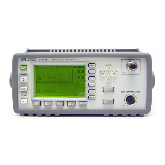
Page 29: The Front Panel At A Glance
The window which is selected is highlighted by a shadowed box. Any measurement setup you create is implemented in the selected window. This key allows you to choose either a one or a two window display. E4418B Power Meter User’s Guide... - Page 30 8 Channel Input. The AGILENT E4418B has one sensor input. Power meters configured with Options 002 or 003 have the sensor inputs on the rear panel and the front panel.
- Page 31 This key allows you to move back one level in the softkey menu. Repeatedly pressing accesses a menu which allows you to increase and decrease the display contrast. 12 Softkeys. These four keys are used to make a selection from the menus. E4418B Power Meter User’s Guide...
-
Page 32: The Display Layout
2 The measurement data is displayed in either one or two rectangular windows depending on the setting of . Pressing allows you to toggle between a one or two window display. E4418B Power Meter User’s Guide... - Page 33 Table 1- 2 for the combination of sensor type and correction being applied to the current measurement. E4418B Power Meter User’s Guide...
-
Page 34: Table 1-1 Relevant Softkeys In Various Mode Of Operation
Series sensors Frequency dependent - None with Option CFT from selected sensor From offset table calibration table E-Series sensors/ Frequency dependent - None N8480 Series downloaded directly from From offset table sensors (excluding sensor Option CFT) E4418B Power Meter User’s Guide... -
Page 35: Selecting Your Display Layout
Display Select using One Window Two Windows Select using Select using Display Format Lower Upper Window Window Select using Analog Digital Display Format Display Display Analog Digital Analog Digital Display Display Display Display E4418B Power Meter User’s Guide... - Page 36 4 Press Display Format (Dgtl should be highlighted). Meter Dgtl Anlg The display shows a digital window. 5 Press . The display now shows two digital windows. E4418B Power Meter User’s Guide...
- Page 37 . The upper window is now the selected window and is highlighted by the black box. 7 Press (Anlg should be Meter Dgtl Anlg highlighted). The upper window now displays an analog meter. 8 Select the digital display using E4418B Power Meter User’s Guide...
-
Page 38: Window Symbols
Confirmation Window This pop- up window is displayed when you are required to press Confirm verify your previous selection. For example, prior to a preset being carried out. E4418B Power Meter User’s Guide... -
Page 39: Wait Symbol
This pop- up window is displayed when you are required to modify numeric or alphanumeric data. The keys move the position of the cursor. keys increment and decrement the alphanumeric digit on which the cursor is currently positioned. E4418B Power Meter User’s Guide... -
Page 40: The Rear Panel At A Glance
This connector allows the power meter to be controlled remotely using the General Purpose Interface Bus. 7 RS232/422 This connector allows the power meter to be controlled remotely using either the RS232 or RS422 serial interface standards. E4418B Power Meter User’s Guide... - Page 41 TTL logic level output when a measurement exceeds a predetermined limit. TTL inputs are also provided to initiate zero and calibration cycles. 10 Ground Connector Binding post, accepts 4 mm plug or bare wire connection. E4418B Power Meter User’s Guide...
-
Page 42: Adjusting The Carrying Handle
Getting Started Adjusting the Carrying Handle To adjust the position, grasp the handle by the sides and pull outward. Rotate the handle to the desired position. Bench top viewing positions Carrying position E4418B Power Meter User’s Guide... -
Page 43: Rack Mounting The Power Meter
Instructions and mounting hardware are included with each rack mounting kit. Any Agilent System II instrument can be rack mounted besides the Agilent E4418B power meter. To rack mount the power meter: 1 Remove the handle by rotating it to the vertical position and pulling the ends outward. - Page 44 5061- 9694 and flange kit 5063- 9212. To install one or two instruments in a sliding support shelf order shelf 5063- 9255 and slide kit 1494- 0015 (for a single instrument, also order filler panel 5002- 3999). E4418B Power Meter User’s Guide...
-
Page 45: Power Meter Operation
E4418B Power Meter User’s Guide Power Meter Operation Introduction Battery Operation (Option 001) Zeroing and Calibrating the Power Meter Making Measurements with the Agilent E-Series Power Sensors and N8480 Series Power Sensors (excluding Option CFT) Making Measurements with the Agilent 8480 Series Power Sensors and... -
Page 46: Introduction
“Saving and Recalling Power Meter Configurations” on page 88. • “How Measurements are Calculated” on page 90 • “Presetting the Power Meter” on page 91. • “Self Test” on page 94. • “Operator Maintenance” on page 101. E4418B Power Meter User’s Guide... - Page 47 Power Meter Operation • “Contacting Agilent Technologies” on page 103. E4418B Power Meter User’s Guide...
-
Page 48: Battery Operation (Option 001)
To obtain a carry case, order Agilent part number 34141A. Do not attempt to recharge the power meter or operate the power meter from an AC power C A U T I O N source while it is contained in the carry case. E4418B Power Meter User’s Guide... -
Page 49: Running Time
When the power meter is running on battery power and there are less than 10 minutes of run- time remaining, the message “Battery Low” appears at the top of the screen. In addition, a pop- up window appears every minute with the message “Battery Power Low”. E4418B Power Meter User’s Guide... -
Page 50: Charging Times
, or On Off Timed If the power meter is connected to an AC power source the backlight menu is greyed out N O T E and the backlight is permanently on. E4418B Power Meter User’s Guide... -
Page 51: Battery Removal/Replacement
Do not dispose of by burning. Refer to your local country regulatory requirements on the disposal of Nickel Metal Hydride batteries. Observe static precautions while removing and replacing the battery module. C A U T I O N E4418B Power Meter User’s Guide... -
Page 52: Figure 2-2 Battery Removal/Replacement
4 Pinch the release tab between finger and thumb while - 5 lightly pressing down on the battery module. Replacing the battery is basically a reversal of the removal procedure. Release Tab Battery Module Closure Assembly Figure 2-2 Battery Removal/Replacement E4418B Power Meter User’s Guide... -
Page 53: Zeroing And Calibrating The Power Meter
“Please Zero + Cal ChA”. If you zero the sensor before calibrating it, the message changes to “Please Cal ChA”. If you calibrate the sensor before zeroing it, the message changes to “Please Zero ChA”. E4418B Power Meter User’s Guide... -
Page 54: Calibrating The Power Meter
An essential part of calibrating is setting the correct reference calibration factor for the power sensor you are using. The Agilent Technologies E4418B Series Power Meter User’s Guide require you to set the reference calibration factor. -
Page 55: Calibration Procedure Using Agilent 8480 Series Power Sensors And N8480 Series Power Sensors With Option Cft
A type sensor while the D type is selected will result in a warning message stating that “Linearity Override May be Required”. To select the linearity type to be applied: Press , or Tables Linearity ATyp DTyp E4418B Power Meter User’s Guide... - Page 56 To calibrate the power meter with a power sensor whose reference calibration factor is 99.8%. • Press • Press . Use the , and keys to enter 99.8. Press Ref CF • Connect the power sensor to the POWER REF output. • Press E4418B Power Meter User’s Guide...
-
Page 57: Table 2-1 Power Sensor Connection Requirements
This power sensor requires an APC 3.5 (f) to 50 Ω (m) N-Type adapter Agilent 8485A Agilent N8485A (08485-60005) to connect to the reference calibrator. Remove this adapter Agilent E4413A before making measurements. Agilent E9300A H24 Agilent E9300A H25 E4418B Power Meter User’s Guide... - Page 58 30 dB reference attenuator and an APC 2.4 (f) to 50 Ω (m) N-Type adapter (08487-60001) should be connected between the power sensor and the reference calibrator. Remove this attenuator from the power sensor input before making measurements. E4418B Power Meter User’s Guide...
-
Page 59: Zeroing And Calibrating Using Ttl Inputs
Figure 2-3 Rmt I/O Port TTL Inputs The TTL inputs are active low and control the zero and calibration functions as shown in Table 2- 2 Table 2-2 TTL Inputs Control Logic Input 1 Input 2 Operation None ZERO E4418B Power Meter User’s Guide... -
Page 60: Table 2-3 Ttl Input Timing Diagram 1
1024 averages x 50 ms = 51.2 s. For front panel operation (in free run mode) the time is 1 x 50 ms. Maximum width of input. Longer inputs may cause a subsequent zero/cal operation some time after the current one is complete. E4418B Power Meter User’s Guide... -
Page 61: Table 2-4 Ttl Inputs Timing Diagram 2
All timings based on 100 ms firmware polling. Table 2-4 TTL Inputs Timing Diagram 2 Timing of zero/cal inputs for condition “00”. Inputs Operation Time Description Value Maximum time between inputs going low. 100 ms Minimum overlap of low inputs. 200 ms E4418B Power Meter User’s Guide... - Page 62 Option CFT) 6 s (N8480 Series with Option CFT) All timings based on 100 ms firmware polling. If both TTL inputs are simultaneously low under any circumstances other than those shown above, the operation is undefined. E4418B Power Meter User’s Guide...
-
Page 63: Making Measurements With The Agilent E-Series Power Sensors And N8480 Series Power Sensors (Excluding Option Cft)
7 To change this setting, press . The power meter displays the frequency Freq in a pop- up window. Modify this frequency (see below) as desired. • Use to modify the digit on which the cursor is currently positioned. E4418B Power Meter User’s Guide... - Page 64 • Connect the power sensor to the POWER REF output. • Press • Press . Use the , and keys to Freq enter 100. Press • Connect the power sensor to the signal to be measured. • The measurement result is now displayed. E4418B Power Meter User’s Guide...
-
Page 65: Making Measurements With The Agilent 8480 Series Power Sensors And N8480 Series Power Sensors With Option Cft
1 Ensure that no power is applied to the power sensor. 2 Press 3 Press . During zeroing, which takes approximately 10 seconds, the wait Zero symbol is displayed. 4 Connect the power sensor to the POWER REF output. E4418B Power Meter User’s Guide... - Page 66 • Use to move to other digits. 9 To confirm your choice, press 10 Connect the power sensor to the signal to be measured. 11 The measurement result is now displayed. E4418B Power Meter User’s Guide...
- Page 67 • Connect the power sensor to the POWER REF output. • Press • Press . Use the , and keys to Cal Fac enter 97.8. Press • Connect the power sensor to the signal to be measured. • The measurement result is now displayed. E4418B Power Meter User’s Guide...
-
Page 68: Making Measurements Using Sensor Calibration Tables
3 Specify the frequency of the signal you want to measure. The calibration factor is automatically set by the power meter from the sensor calibration table. Refer to “Making the Measurement” on page 45 for further information. 4 Make the measurement. E4418B Power Meter User’s Guide... -
Page 69: Selecting A Sensor Calibration Table
3 The setting of the reference calibration factor is obtained from the sensor calibration table and displayed under the softkey. Ref CF 4 Connect the power sensor to the POWER REF output. E4418B Power Meter User’s Guide... -
Page 70: Editing Sensor Calibration Tables
You can edit sensor calibration tables using the “Edit Cal” menu as shown Figure 2- 5. To view the sensor calibration tables currently stored in the power meter, press . The “Sensor Tables Sensor Cal Tables Tbls” screen is displayed as shown in Figure 2- E4418B Power Meter User’s Guide... -
Page 71: Figure 2-5 "Edit Cal Screen
1 DEFAULT is a sensor calibration table in which the reference calibration factor and calibration factors are 100%. This sensor calibration table can be used during the performance testing of the power meter. 2 The Agilent 8482B and Agilent 8482H power sensors use the same data as the Agilent 8482A. E4418B Power Meter User’s Guide... - Page 72 3 To confirm your choice, press the appropriate softkey. 4 To add a new sensor calibration table entry, press . You are prompted Insert for the frequency and calibration factor. The entry is sorted by frequency. E4418B Power Meter User’s Guide...
- Page 73 If you measure a signal with a frequency outside the frequency range defined in the sensor calibration table, the power meter uses the highest or lowest frequency point in the sensor calibration table to calculate the calibration factor. E4418B Power Meter User’s Guide...
- Page 74 13 GHz 98.9 30 MHz 98.1 14 GHz 99.4 100 MHz 97.6 15 GHz 98.9 300 MHz 97.5 16 GHz 99.1 1 GHz 17 GHz 98.4 2 GHz 18 GHz 100.1 3 GHz 4.2 GHz E4418B Power Meter User’s Guide...
- Page 75 8 GHz 98.3 35 GHz 97.6 10 GHz 98.1 36 GHz 11 GHz 97.8 37 GHz 98.2 12 GHz 97.6 38 GHz 97.4 12.4 GHz 97.6 39 GHz 97.6 14 GHz 97.4 40 GHz 16 GHz E4418B Power Meter User’s Guide...
- Page 76 Agilent Q8486A 29 GHz 94.4 45 GHz 88.2 30 GHz 46 GHz 31 GHz 93.7 47 GHz 86.4 32 GHz 93.8 48 GHz 85.3 33 GHz 49 GHz 84.7 34 GHz 93.2 50 GHz 82.9 E4418B Power Meter User’s Guide...
-
Page 77: Making Measurements Using Frequency Dependent Offset Tables
(if selected) and the frequency dependent offset table. Refer to “Making the Measurement” on page 45 for further information. 4 Make the measurement. E4418B Power Meter User’s Guide... -
Page 78: Selecting A Frequency Dependent Offset Table
. The “State” field Tables Freq Dep Offset Table Off On indicates if any frequency dependent offset tables are currently selected. The “Offset Tbls” screen is displayed as shown in Figure 2- Figure 2-6 “Offset Tbls” Screen E4418B Power Meter User’s Guide... -
Page 79: Making The Measurement
• Use to move to other digits. 8 To confirm your choice, press the appropriate frequency unit. 9 Connect the power sensor to the signal to be measured. 10 The measurement result is now displayed. E4418B Power Meter User’s Guide... -
Page 80: Editing Frequency Dependent Offset Tables
Figure 2- To view the frequency dependent offset tables currently stored in the power meter, press . The “Offset Tbls” Tables Freq Dep Offset screen is displayed as shown in Figure 2- Figure 2-7 “Edit” Screen E4418B Power Meter User’s Guide... - Page 81 5 To remove a frequency dependent offset table entry, use the , and keys to select the entry, press . If you delete the Delete frequency, the equivalent offset is also removed and vice versa. E4418B Power Meter User’s Guide...
- Page 82 If you measure a signal with a frequency outside the frequency range defined in the frequency dependent offset table, the power meter uses the highest or lowest frequency point in the frequency dependent offset table to calculate the offset. E4418B Power Meter User’s Guide...
-
Page 83: Setting The Units Of Measurement
Measurement Mode Relative Mode Off Relative Mode On Linear Linear Single Channel Watt 1 When relative mode is on (that is, Rel Off On is “ ”), the measurement is com- pared to a reference value. E4418B Power Meter User’s Guide... -
Page 84: Selecting Units Of Measurement From The Softkeys
Some softkeys may be grayed out so that an invalid value cannot be entered. N O T E Increment Multiplier Decrement Multiplier Pressing increases or decreases the multiplier shown in front of . Pressing after the correct multiplier has been selected confirms the entry. E4418B Power Meter User’s Guide... -
Page 85: Making Relative Measurements
“On”, when is pressed. Rel Off On Successive measurements are now displayed relative to the reference value. The relative mode can be disabled and re- enabled simply by pressing Rel Off On E4418B Power Meter User’s Guide... -
Page 86: Setting The Resolution
1 Press . The current setting of the resolution is highlighted on the softkey. Resolution 1 2 3 2 To change this setting, press until the required Resolution 1 2 3 4 resolution setting is highlighted. E4418B Power Meter User’s Guide... -
Page 87: Setting Offsets
4 To confirm your choice, press Offset Off On is automatically set to “On” when a value is entered using Offset Channel offsets can be disabled and re- enabled simply by pressing Offset Off On E4418B Power Meter User’s Guide... -
Page 88: Setting Display Offsets
Ch Offset Display Offset Display ON POWER † †† Offset Offset METER DISPLAY Figure 2-8 Effect of Offsets on a Channel Measurement Input Settings Offset † Channel Offset entered using Offset †† Display Offset entered using E4418B Power Meter User’s Guide... -
Page 89: Setting Averaging
A and the lower window has a resolution of four and is also measuring channel A. In this instance, channel A averaging is calculated with a resolution of four. E4418B Power Meter User’s Guide... -
Page 90: Figure 2-9 Averaged Readings
. A pop- up window appears. Use Length , or keys to set your filter length. 3 To confirm your choice, press Enter The filter can be disabled and re- enabled simply by pressing Filter Off On E4418B Power Meter User’s Guide... -
Page 91: Step Detection
To set step detection: 1 Press Input Settings 2 Press the softkey to access the filter menu. Filter 3 Use the Step Det Off On softkey to enable or disable step detection. E4418B Power Meter User’s Guide... -
Page 92: Measuring Pulsed Signals
Pulse measurements are not recommended using Agilent E4412A and E4413A power N O T E sensors. An example of a pulsed signal is shown in Figure 2- Power Duty Cycle = Time Figure 2-10 Pulsed Signal E4418B Power Meter User’s Guide... - Page 93 In order to ensure accurate pulse power readings, the input signal must be pulsed with a rectangular pulse. Other pulse shapes (such as triangle, chirp, or Gaussian) will cause erroneous results. The pulse power on or off ratio must be much greater than the duty cycle ratio. E4418B Power Meter User’s Guide...
-
Page 94: Setting Measurement Limits
• Use to move to other digits. 3 To confirm your choice, press the appropriate measurement units. Limits can be disabled and re- enabled simply by pressing Limits Off On E4418B Power Meter User’s Guide... -
Page 95: Figure 2-11 Limits Checking Application
Device Under Test. The power meter measures the output power. The limits have been set at +4 dBm and +10 dBm. A fail occurs each time the output power is outside these limits as shown in Figure 2- E4418B Power Meter User’s Guide... -
Page 96: Setting Window Limits
TTL output represents an over limit condition, under limit condition or both. The TTL connector is an RJ- 45 Series shielded modular jack assembly with the TTL output pins connected as shown in Figure 2- E4418B Power Meter User’s Guide... -
Page 97: Figure 2-13 Remote I/O Ttl Outputs
• Use to move to other digits. 3 To confirm your choice, press the appropriate measurement units. Limits can be disabled and re- enabled simply by pressing Limits Off On E4418B Power Meter User’s Guide... -
Page 98: Checking For Limit Failures
Limit failures are displayed in the appropriate field in the measurement window on the power meter’s display as shown in Figure 2- The same limit fail field is used by both channel and window limits. N O T E E4418B Power Meter User’s Guide... -
Page 99: Figure 2-14 Pass/Fail Limit Indicators
“Undr Lmt”. This measurement has failed as the result is more than the maximum limit level set of –60 dBm. This is indicated with the text “Over Lmt”. Figure 2-14 Pass/Fail Limit Indicators E4418B Power Meter User’s Guide... -
Page 100: Selecting A Digital Or Analog Display
The measurement windows can display the result in either a digital or analog format or both as shown in the following figures. Figure 2-15 Digital Display Figure 2-16 Analog Display Figure 2-17 Digital and Analog Display E4418B Power Meter User’s Guide... - Page 101 . If the measurement unit selected is linear, then choose the appropriate softkeys from the following menus: μ Cancel Cancel Increment Increment Multiplier Multiplier Decrement Decrement Multiplier Multiplier Cancel Cancel E4418B Power Meter User’s Guide...
- Page 102 That is, it does not indicate when duty cycle, range hold, offset, or relative mode are enabled. In addition, it does not indicate if the measurement is within the test limits if any are set. E4418B Power Meter User’s Guide...
-
Page 103: Setting The Range
. The current setting of the range is Input Settings displayed under the softkey. Range 2 To change this setting, press . A pop- up window appears. Use Range to highlight your choice. 3 To confirm your choice, press Enter E4418B Power Meter User’s Guide... -
Page 104: Configuring The Remote Interface
• Use to move to other digits. 3 To confirm your choice, press Enter To set the GPIB address from the remote interface, use the SYSTem:COMMunicate:GPIB:ADDRess command. E4418B Power Meter User’s Guide... -
Page 105: Rs232/Rs422
CTS+ RTS- Figure 2-18 RS232/ 422 Pin Assignment Setting the RS232/422 Parameters This section explains how to set the baud rate, word size, parity, number of stop bits, pacing, and echo for the serial interface. E4418B Power Meter User’s Guide... - Page 106 When enabled “Xon” is highlighted, otherwise “None” is highlighted. 11 Press and use any of the arrow keys to select one of the RTS/CTS following from the pop- up menu: OFF - Sets the RTS signal line permanently low. E4418B Power Meter User’s Guide...
-
Page 107: Remote Interface Overview
Remote Interface Overview You can view a summary of your remote interface settings at any time by pressing . Examples of an Remote Interface Interface Overview GPIB and RS422 interface overview are shown in Figure 2- E4418B Power Meter User’s Guide... -
Page 108: Figure 2-19 Interface Overview Examples
Power Meter Operation Figure 2-19 Interface Overview Examples Pressing the softkey returns the power meter display to the previous Done screen. E4418B Power Meter User’s Guide... -
Page 109: Programming Language Selection
To select the interface language from the front panel: 1 Press Remote Interface Command Set 2 Select the language you require from HP 437B SCPI To select the interface language from the remote interface, use the SYSTem:LANGuage command E4418B Power Meter User’s Guide... -
Page 110: Recorder Output
This menu allows you to switch the Recorder Output signal either on or off. The softkeys allow you to enter the input Max Power Min Power power level that you want to represent the 1 Vdc maximum and 0 Vdc minimum output voltage of the Recorder Output. E4418B Power Meter User’s Guide... -
Page 111: Leveling A Source Output
–50 dBm (10 nW) –60 dBm (1 nW) 3 To set the maximum value, press and enter the appropriate Max Power value. 4 Press and enter 0 W. Min Power 5 Press to “On”. Output Off On E4418B Power Meter User’s Guide... -
Page 112: Saving And Recalling Power Meter Configurations
3 To confirm your choice, press Enter To recall a measurement setup: 1 Press 2 Use the keys to scroll through the displayed files. When the required file is highlighted, press Recall 3 Press Confirm E4418B Power Meter User’s Guide... -
Page 113: Figure 2-21 "Save/Recall" Screen
Power Meter Operation Figure 2-21 “Save/Recall” Screen E4418B Power Meter User’s Guide... -
Page 114: How Measurements Are Calculated
Upper Window Channel A Channel Duty Freq Dep Display Averaging Relative Cal Factor Offset Cycle Offset Offset Limits Window Recorder Limits Output Lower Window Display Relative Offset Window Limits Figure 2-22 How Measurements are Calculated E4418B Power Meter User’s Guide... -
Page 115: Presetting The Power Meter
90.000 dBm ( ) and –90.000 dBm ( Limits • is set to “Off”. TTL Output Off/On • is set to “OVER”. Limits OVER, UNDER, EITHER • is set to “Low” Fail O/P High/Low E4418B Power Meter User’s Guide... - Page 116 “Off”. Recorder Output • is set to 100.0 mW ( ) and 0.00 W Max Power Min Power • is set to “Off”. Output Off/On Must Cal Off/On • is not affected. E4418B Power Meter User’s Guide...
- Page 117 Power Meter Operation • Backlight Off/On is set to “On” • Ref CF is set to 100%. • Must Cal Off/On is not affected. • TTL Inputs Off/On is set to “Off”. E4418B Power Meter User’s Guide...
-
Page 118: Self Test
“Not Present”. If a failure occurs, the message “Power- up H/W Err” appears. Any errors are also written to the error queue and can be examined in the “Errors” screen by pressing Error List E4418B Power Meter User’s Guide... -
Page 119: Front Panel Selection Of Self Tests
Each of these tests can be run individually. Information on the instrument self test and confidence check are described on page 96. Refer to “Test Descriptions” on page 98, if you require a description of the other tests. E4418B Power Meter User’s Guide... - Page 120 2 The power meter automatically makes a power measurement. If the measured error is within the instrument accuracy specification, the confidence check has been successful. While the test is running, the message “Testing...” appears. If the correct E4418B Power Meter User’s Guide...
-
Page 121: Remote Testing
While a test is running, the message “Testing...” appears next to the name of the test. As each stage of the test is completed, the message “Testing...” is replaced by either the message “Passed” or “Failed”. E4418B Power Meter User’s Guide... -
Page 122: Test Descriptions
This self test returns either a pass or a fail. A fail can either be produced by the measurement assembly self test failing or by the measurement assembly not responding. This test confirms that the internal cooling fan is operating. E4418B Power Meter User’s Guide... - Page 123 If the test is exited without all the keys being pressed, a list is displayed showing all the keys which were not selected. Display Three tests are available for the display: the display assembly, display RAM and bitmap display. E4418B Power Meter User’s Guide...
- Page 124 A series of bitmaps are displayed on the power meter showing: two checkboards, vertical lines, horizontal lines, oblique lines, all pixels on and all pixels off. Pressing cycles you through these bitmaps. The key stops the display and returns you to the previous menu. E4418B Power Meter User’s Guide...
-
Page 125: Operator Maintenance
This section describes how to replace the power line fuse and clean the power meter. If you need additional information about replacing parts or repairing the power meter, refer to the Agilent E4418B/E4419B Service Guide. To clean the power meter, disconnect its supply power and wipe with a damp cloth only. -
Page 126: Figure 2-23 Replacing The Fuse
Power Meter Operation In line fuse Spare fuse Figure 2-23 Replacing the fuse E4418B Power Meter User’s Guide... -
Page 127: Contacting Agilent Technologies
If you have a problem with your power meter, first refer to this section . This chapter contains a checklist that will help identify some of the most common problems. If you wish to contact Agilent Technologies about any aspect of the power meter, from service problems to ordering information, refer to “Sales and Service Offices”... -
Page 128: Check The Basics
A few minutes spent in performing these simple checks may eliminate time spent waiting for instrument repair. Before calling Agilent Technologies or returning the power meter for service, please make the following checks: • Check that the line socket has power. - Page 129 This is a code identifying the date of the last major design change. • The suffix indicates an alpha numeric code which is used to ensure unique identification of each product throughout Agilent Technologies. SERIAL NUMBER SER MY12345678...
-
Page 130: Sales And Service Offices
Power Meter Operation Sales and Service Offices For more information about Agilent Technologies test and measurement products, applications, services, and for a current sales office listing, visit our web site:http://www.agilent.com You can also contact one of the following centers and ask for a test and measurement sales representative. -
Page 131: Returning Your Power Meter For Service
In any correspondence or telephone conversations, refer to the power meter by its model number and full serial number. With this information, the Agilent Technologies representative can quickly determine whether your unit is still within its warranty period. Returning Your Power Meter for Service Use the information in this section if you need to return your power meter to Agilent Technologies. - Page 132 4 Seal the shipping container securely with strong nylon adhesive tape. 5 Mark the shipping container “FRAGILE, HANDLE WITH CARE” to ensure careful handling. 6 Retain copies of all shipping papers. E4418B Power Meter User’s Guide...
- Page 133 E4418B Power Meter User’s Guide Menu Reference Introduction The Front Panel Menu Maps Front Panel Menu Reference Agilent Technologies...
-
Page 134: Menu Reference
This chapter is a reference to the softkey menu structure of the power meter. “The Front Panel Menu Maps” starting on page 111 details the menus diagrammatically. “Front Panel Menu Reference” starting on page 120 details the menus descriptively. E4418B Power Meter User’s Guide... -
Page 135: The Front Panel Menu Maps
Depending on the power meter’s setup, you will be unable to select certain softkeys. The N O T E text on these softkey labels appears grayed out. Refer to the appropriate softkey descriptions for further information. E4418B Power Meter User’s Guide... -
Page 136: Frequency/Cal Fac Menu
Depending on the power meter’s setup, you will be unable to select certain softkeys. The N O T E text on these softkey labels appears grayed out. Refer to the appropriate softkey descriptions for further information. E4418B Power Meter User’s Guide... -
Page 137: Meas Setup Menu
20.000 dBm Meter Dgtl Anlg –70.000 dBm Anlg Mtr Scaling Display Format Resolution 1 2 3 4 Limits Off On 90.000 dBm TTL Output Off On –90.000 dBm Limits OVER Output Fail O/P High Low E4418B Power Meter User’s Guide... -
Page 138: Rel/Offset Menu
Depending on the power meter’s setup, you will be unable to select certain N O T E softkeys. The text on these softkey labels appears grayed out. Refer to the appropriate softkey descriptions for further information. E4418B Power Meter User’s Guide... -
Page 139: System Inputs Menu (1 Of 4)
Depending on the power meter’s setup, you will be unable to select certain softkeys. The N O T E text on these softkey labels appears grayed out. Refer to the appropriate softkey descriptions for further information. E4418B Power Meter User’s Guide... -
Page 140: System Inputs Menu (2 Of 4)
Instrument Assy Memory Self Test Display Lithium Confidence Battery Check Bitmap Displays Measure Individual Assembly Calibrator UART Config Keyboard Local Loop Back RS232 Display Loop Back Set Contrast RS422 Serial Loop Back Set Brightness Interface E4418B Power Meter User’s Guide... -
Page 141: System Inputs Menu (3 Of 4)
Remote RS422 Interface Configure Interface Baud Rate Interface 9600 Overview GPIB (See page 115) Word Size Serial Stop Bits Tx Pacing None Xon Parity NONE Rx Pacing None Xon Pacing RTS/CTS Echo On Off DTR/DSR E4418B Power Meter User’s Guide... -
Page 142: System Inputs Menu (4 Of 4)
System Inputs Menu (4 of 4) Error List (See page 116) Recorder Output Self Test Service Display (See page 116) Must Cal Tx Break Off On Version Status Serial Diagnostic Reset Battery Backlight Backlight Backlight Timed Done E4418B Power Meter User’s Guide... -
Page 143: Zero/Cal Menu
Depending on the power meter’s setup, you will be unable to select certain softkeys. The N O T E text on these softkey labels appears grayed out. Refer to the appropriate softkey descriptions for further information. E4418B Power Meter User’s Guide... -
Page 144: Front Panel Menu Reference
Press this softkey to display the measurement results in dBm. • Press this softkey to display the measurement results in Watts. • Press this softkey to display the measurement results in dB. • Press this softkey to display the measurement results in %. E4418B Power Meter User’s Guide... -
Page 145: Table 3-1 Combination Of Sensor Type And Correction Applied To Current Measurement
Default value obtained from the entered if a entered. Default Option CFT is 50 MHz. sensor calibration frequency value is 100%. table but can be dependent offset overridden by this table is selected. softkey. E4418B Power Meter User’s Guide... - Page 146 Meter Dgtl Anlg • Press this softkey to toggle between an analog and digital display. Refer “Selecting a Digital or Analog Display” on page 76 for further information. E4418B Power Meter User’s Guide...
- Page 147 90.000 dBm, 1 mW, 60 dB, or 100M% depending on the windows unit. Use the , and keys to change the value. To confirm your choice, press the appropriate measurement units. must be greater than E4418B Power Meter User’s Guide...
- Page 148 The bottom right of the power meter display indicates the number of pages in the menu. For example, if “1 of 2” is displayed, pressing moves you to “2 of 2”. Pressing again moves you back to “1 of 2”. E4418B Power Meter User’s Guide...
- Page 149 Press this softkey to use the current reading as the reference value. This allows you to compare any measurement result in dB or percentage (%). Rel Off On is automatically set to “On” when is pressed. E4418B Power Meter User’s Guide...
- Page 150 Use the Insert Char , and Delete Char keys to change the file name. To confirm your choice, press Enter • Enter Press this softkey to accept your edited file name as a new name. E4418B Power Meter User’s Guide...
- Page 151 Refer to “Programming Language Selection” on page 85 for further information. SCPI ■ Press this softkey to select SCPI (Standard Commands for Programmable Instruments) as the remote programming language you want to use. E4418B Power Meter User’s Guide...
- Page 152 80 for further information. Serial ■ Press this softkey to access a menu which allows you to set baud rate, word size, parity, number of stop bits, pacing and echo for the serial interface. E4418B Power Meter User’s Guide...
- Page 153 Press this softkey to obtain a pop- up window which allows you to select one of the following: OFF - Sets the RTS signal line permanently low. ON - Sets the RTS signal line permanently high. E4418B Power Meter User’s Guide...
- Page 154 Use the , and keys to move between the name, frequency, calibration factors and offsets. Press Change Insert , or Delete as follows: E4418B Power Meter User’s Guide...
- Page 155 Press this softkey to modify the highlighted parameter, which is either a frequency, calibration factor, offset or table name. A pop- up window displays the parameter. Use the keys to change the parameter value. To confirm your Enter choice, press E4418B Power Meter User’s Guide...
- Page 156 A. • Offset Off On Press this softkey to toggle the channel offset value on or off. The default Offset is “Off”. The offset value is set using E4418B Power Meter User’s Guide...
- Page 157 Duty Cycle Off On • Press this softkey to toggle the duty cycle value on or off. The default is Duty Cycle “Off”. The duty cycle value is set using E4418B Power Meter User’s Guide...
- Page 158 Press this softkey to switch step detection on or off. Step detection reduces the settling time of the filter by re- initialising the filter after a significant step (increase or decrease) has been detected in the measured power. The default is “On”. E4418B Power Meter User’s Guide...
- Page 159 Recorder Output produces a DC voltage that corresponds to the selected input channel power level in Watts. Max Power • Press this softkey to enter the input power level that you want to represent the 1 Vdc maximum output voltage of the Recorder Output. E4418B Power Meter User’s Guide...
- Page 160 Press this softkey to run a self test on the measurement assembly. Refer to “Measurement Assembly” on page 98 for further information. Calibrator ■ Press this softkey to make internal voltage measurements on the 50 MHz reference oscillator. Keyboard ■ E4418B Power Meter User’s Guide...
- Page 161 The test connector must have the following pins jumpered: Tx (3) and Rx (2), RTS (7) and CTS (8), DTR (4) and DSR (6). This test will only run if the RS232 interface is currently selected. E4418B Power Meter User’s Guide...
- Page 162 Set Brightness Press this softkey to set the brightness. Note, this key changes the factory default setting. Version • Press this softkey to display: the model number; option structure; serial number; firmware, bootrom and DSP revisions. E4418B Power Meter User’s Guide...
- Page 163 10 minutes after the last key is pressed. To turn the backlight on again, press any key. While operating with AC power connected, these keys are grayed out and the backlight is permanently on. On instrument preset, the Backlight is set to “On” • Backlight On E4418B Power Meter User’s Guide...
- Page 164 1% to 150% can be entered. The default value is obtained from the sensor calibration table if one is selected, otherwise it is 100%. Use the keys to change the value. To E4418B Power Meter User’s Guide...
- Page 165 This softkey is coupled to the equivalent softkey in the System Inputs menu. • TTL Inputs Off On Press this softkey to disable or enable (Off/On) the ZERO and CAL rear panel TTL inputs. E4418B Power Meter User’s Guide...
-
Page 166: Diagrammatical Keys
Z through A, then underscore. • select fields for editing on the “Edit Table” screen. • select a table in the “Sensor Cal Tables” screen. • select a file in the “Save” and “Recall” screens. E4418B Power Meter User’s Guide... - Page 167 (that is, when this key is off but the power is connected to the instrument) the red LED is lit. When the power meter is switched on, the green LED is lit. E4418B Power Meter User’s Guide...
- Page 168 Menu Reference THIS PAGE HAS BEEN INTENTIONALLY LEFT BLANK. E4418B Power Meter User’s Guide...
-
Page 169: Error Messages
E4418B Power Meter User’s Guide Error Messages Introduction Error Messages Agilent Technologies... -
Page 170: Introduction
To read the error queue from the front panel press: • Error List then use Next to scroll through each error message. To read the error queue from the remote interface use: • the SYSTem:ERRor? command. E4418B Power Meter User’s Guide... - Page 171 Error Messages Error queue messages have the following format: Error Device ‚ ‚ Error Number Dependent Info Description For example, –330, “Self-test Failed;Battery Fault”. Errors are retrieved in a first in first out (FIFO) order. If more than 30 errors occur, the error queue overflows and the last error in the queue is replaced with error -350, “Queue Overflow”.
-
Page 172: Error Messages
For example, TRIG:SOUR IMM –121 Invalid character in number An invalid character was found in the number specified for a parameter value. For example, SENS:AVER:COUN 128#H E4418B Power Meter User’s Guide... - Page 173 Error Messages –123 Exponent too large A numeric parameter was found whose exponent was larger than 32,000. For example, SENS:COUN 1E34000 –124 Too many digits A numeric parameter was found whose mantissa contained more than 255 digits, excluding leading zeros. –128 Numeric data not allowed A numeric value was received within a command which does not accept a numeric value.
- Page 174 A discrete parameter was received which was not a valid choice for the command. You may have used an invalid parameter choice. For example, TRIG:SOUR EXT –226 Lists not same length This occurs when SENSe:CORRection:CSET[1]|CSET2:STATe is set to and the frequency and calibration/offset lists do not correspond in length. E4418B Power Meter User’s Guide...
- Page 175 Error Messages –230 Data corrupt or stale This occurs when a is attempted and either a reset has been received or the power FETC? meter state has changed such that the current measurement is invalidated (for example, a change of frequency setting or triggering conditions). –230 Data corrupt or stale;Please zero and calibrate Channel A When...
- Page 176 98 if you require a description of the Measurement Assembly test. –330 Self-test Failed;Option 001 Battery requires replacement The Option 001 battery is not charging to a satisfactory level and should be replaced. E4418B Power Meter User’s Guide...
- Page 177 Error Messages –330 Self-test Failed;RAM Battery Fault Refer to “RAM Battery” on page 98 if you require a description of the battery test. –330 Self-test Failed;Calibrator Fault Refer to “Calibrator” on page 99 if you require a description of the calibrator test. –330 Self-test Failed;ROM Check Failed Refer to...
- Page 178 A command was received which generates too much data to fit in the output buffer and the input buffer is also full. Command execution continues but data is lost. –440 Query UNTERMINATED after indefinite response command must be the last query command within a command string. *IDN? E4418B Power Meter User’s Guide...
- Page 179 E4418B Power Meter User’s Guide Specifications Introduction Power Meter Specifications Power Meter Supplemental Characteristics Battery Option 001 Operational Characteristics General Characteristics Environmental Characteristics General Agilent Technologies...
-
Page 180: Specifications
These characteristics are shown in italics or denoted as “typical”, “nominal” or “approximate”. For information on measurement uncertainty calculations, refer to Agilent Application Note 64- 1A, “Fundamentals of RF and Microwave Power Measurements”, Literature Number 5965- 6630E. E4418B Power Meter User’s Guide... -
Page 181: Power Meter Specifications
Selectable resolution of: 1.0, 0.1, 0.01, and 0.001 dB in logarithmic mode or 1, 2, 3, and 4 significant digits in linear mode Default Resolution 0.01 dB in logarithmic mode 3 digits in linear mode E4418B Power Meter User’s Guide... -
Page 182: Accuracy
Agilent 8485D ±20 pW Agilent R8486A ±50 nW Agilent R8486D ±30 pW Agilent Q8486A ±50 nW Agilent Q8486D ±30 pW Agilent V8486A ±200 nW Agilent W8486A ±200 nW Agilent 8487A ±50 nW Agilent 8487D ±20 pW E4418B Power Meter User’s Guide... - Page 183 Agilent N8485A with Option CFT ±63 nW Agilent N8486AR with Option CFT ±63 nW Agilent N8486AQ with Option CFT ±63 nW Agilent N8487A with Option CFT ±63 nW 1 The zero set specifications are tested at 50 MHz. E4418B Power Meter User’s Guide...
-
Page 184: Mw Power Reference1
Poids et Mesures Mutual Recognition Arrangement. Further information is available from the Bureau International des Poids et Mesures, at http://www.bipm.fr/ 2. This SWR specification is only warranted for the E4418B and the E4419B Power Meters with serial prefix GB4331xxxx/MYxxxxxxxx and above. Prior to this prefix the values shown are supplemental characteristics. -
Page 185: Power Meter Supplemental Characteristics
• Fast: 200 readings/second, for Agilent E- Series power sensors only Maximum measurement speed is obtained using binary output in free run trigger mode. Zero Drift of Sensors Power sensor dependent (refer to Table 5- E4418B Power Meter User’s Guide... -
Page 186: Measurement Noise
Agilent 8482B <±10 mW <110 mW Agilent 8482H <±1 mW <10 mW Agilent 8483A <±10 nW <110 nW Agilent 8485A <±10 nW <110 nW Agilent 8485D <±4 pW <45 pW Agilent R8486A <±10 nW <110 nW E4418B Power Meter User’s Guide... - Page 187 Agilent N8482H (exclude Option <±0.3 µW <8 µW CFT) Agilent N8485A (exclude Option <±3 nW <80 nW CFT) Agilent N8486AR (exclude Option <±3 nW <80 nW CFT) Agilent N8486AQ (exclude Option <±3 nW <80 nW CFT) E4418B Power Meter User’s Guide...
- Page 188 For Agilent E-Series power sen- sors, the measurement noise is measured within the low range. Refer to the relevant power sensor manual for further information. 3 The zero drift and measurement noise specifications are tested at 50 MHz. E4418B Power Meter User’s Guide...
-
Page 189: Settling Time
Settling 200 ms 180 ms 10 dB 10 dB Dynamic Dynamic Times Times Range Range 500 ms 350 ms 10 dB 10 dB 6.6 s 3.5 s 10 dB 10 dB Minimum dBm Minimum dBm E4418B Power Meter User’s Guide... -
Page 190: Table 5-5 Settling Time
For Agilent E- Series power sensors in normal and x2 speed modes, manual filter, 10 dB decreasing power step: Table 5-5 Settling Time Number of Averages 1024 Settling Time (s) 0.07 0.12 0.21 (Normal Mode) Response Time (s) 0.04 0.07 0.12 0.21 14.2 (x2 mode) E4418B Power Meter User’s Guide... - Page 191 Settling Dynamic Dynamic Times Times Range Range 120 ms 70 ms 10 dB 10 dB 400 ms 210 ms 10 dB 10 dB 6.5 s 3.4 s 10 dB 10 dB Minimum dBm Minimum dBm E4418B Power Meter User’s Guide...
-
Page 192: Table 5-6 Settling Time
Sensor Settling Settling Dynamic Dynamic Times Times Range Range 400 ms 10 dB 10 dB 6.6 s 3.6 s 10 dB 10 dB 13.5 s 6.6 s 5 dB 5 dB Minimum dBm Minimum dBm E4418B Power Meter User’s Guide... -
Page 193: Power Sensor Specifications
This parameter is also known as short term stability and is specified as the change in the power meter indication over a short time interval (usually one minute) for a constant input power at a constant temperature. E4418B Power Meter User’s Guide... -
Page 194: Battery Option 001 Operational Characteristics
LED backlight OFF. Power meter is operational while it is charging. Service Life To 70% of initial capacity at 25 °C: approximately 450 charge or discharge cycles. Chemistry Nickel Metal Hydride. Weight 1 kg. E4418B Power Meter User’s Guide... -
Page 195: General Characteristics
Binding post, accepts 4 mm plug or bare wire connection. Line Power • Input Voltage Range: 85 to 264 Vac, automatic selection • Input Frequency Range: 50 to 440 Hz • Power Requirement: approximately 50 VA (14 Watts) E4418B Power Meter User’s Guide... -
Page 196: Environmental Characteristics
15% at 40 ºC (non- condensing) Maximum Altitude 3000 meters (9840 feet) Storage Conditions Storage Temperature –20 ºC to +70 ºC Non-Operating Maximum Humidity 90% at 65 ºC (non- condensing) Non-Operating Maximum Altitude 15240 meters (50000 feet) E4418B Power Meter User’s Guide... -
Page 197: General
7.9 Kg (17.4 lb), 8.9 Kg (19.6 lb) with Option 001 Safety Conforms to the following Product Specifications: • EN61010- 1: 1993/IEC 1010- 1:1990+A1/CSA C22.2 No. 1010- 1:1993 • EN60825- 1: 1994/IEC 825- 1: 1993 Class 1 • Low Voltage Directive 72/23/EEC E4418B Power Meter User’s Guide... -
Page 198: Remote Programming
SCPI standard interface commands. Agilent 437B code compatible. GPIB Compatibility SH1, AH1, T6, TE0, L4, LE0, SR1, RL1, PP1, DC1, DT1, C0 Nonvolatile Memory Battery Lithium Polycarbon Monoflouride, approximate lifetime 5 years at 25 °C. E4418B Power Meter User’s Guide... - Page 199 Product specifications and descriptions in this document are subject to change without notice. Always refer to the Agilent Web site for the lat- est revision. © Agilent Technologies, Inc. 1998–2013 Printed in Malaysia Eighth Edition, April 5, 2013 E4418-90032 Agilent Technologies...