Table of Contents
Advertisement
Quick Links
Advertisement
Chapters
Table of Contents
Troubleshooting

Related Manuals for Agilent Technologies 1290 Infinity II 2D-LC Solution


Summary of Contents for Agilent Technologies 1290 Infinity II 2D-LC Solution
- Page 1 Agilent 1290 Infinity II 2D-LC Solution User Guide 2D-LC - User Guide...
- Page 2 Agilent Technologies, Inc. as understood and met. furnishing, use, or performance of this governed by United States and interna- document or of any information con- tional copyright laws.
- Page 3 2D-LC. Run the System This chapter describes how to run the Agilent 1290 Infinity II 2D-LC Solution in the modes standard heart-cutting, multiple heart-cutting, high resolution sampling and comprehensive 2D-LC. 2D-LC - User Guide...
- Page 4 Investigate the effects of using different gradients in the 2Dimension This chapter describes, how shifted gradients in the second dimension can be used to enlarge the accessible two-dimensional separation space. Data Analysis This chapter descibes the analyzation of data in 2D-LC and is separated in a section heart-cutting 2D-LC and a section comprehensive 2D-LC.
- Page 5 Theoretical Background This chapter gives the theoratical background of 2D-LC and describes the system components (soft- and hardware) of the Agilent 1290 Infinity II 2D-LC Solution. Appendix This chapter provides addition information on safety, legal and web. 2D-LC - User Guide...
-
Page 6: Table Of Contents
Contents Introduction Product Description Features Concepts of 2D-LC Concepts of 2D-LC Heart-Cutting 2D-LC (LC-LC) Multiple Heart-Cutting and High Resolution Sampling 2D-LC Comprehensive 2D-LC (LCxLC) Triggering of 2D-LC Active solvent Modulation (ASM) Compatibility Matrix Supported Chromatographic Data Systems Supported Drivers Supported Operating Systems Supported Firmware Available Languages PC Requirements... - Page 7 Method Parameters Method Parameters Standard Heart-Cutting 2D-LC Method Parameters Multiple Heart-Cutting and High Resolution Sampling 2D-LC Method Parameters Comprehensive 2D-LC Method Development of Active Solvent Modulation (ASM) Run the System Connect the capillaries to the 2D-LC valve Standard Heart-Cutting 2D-LC Multiple Heart-Cutting and High Resolution Sampling 2D-LC Comprehensive 2D-LC Active Solvent Modulation (ASM)
- Page 8 Maintenance Introduction to Maintenance Warnings and Cautions Overview of Maintenance Cleaning the Module Correcting Leaks Replace Valve Heads Replacing Parts of the Valve Head Replacing the Fuses of the Infinity Valve Drive Replace the Module Firmware Parts for Maintenance 2D-LC Loops 2D-LC Capillaries ASM Capillaries Pressure Release Kit...
- Page 9 Theoretical basis of 2D-LC 2nd dimension as detector Successful Mode Combinations Solvent Elution Modes Practical Issues Appendix General Safety Information Waste Electrical and Electronic Equipment (WEEE) Directive Radio Interference Sound Emission Solvent Information Further Information Agilent Technologies on Internet 2D-LC - User Guide...
-
Page 10: Introduction
Introduction Product Description Features This chapter describes the product of Agilent 1290 Infinity II 2D-LC Solution. 2D-LC - User Guide... -
Page 11: Product Description
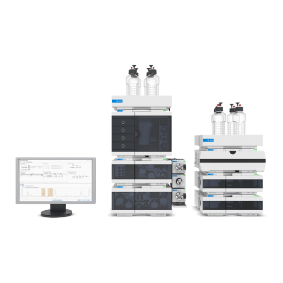
Pre-configured systems and a dedicated 2D-LC training allow an easy start into 2D-LC. The Agilent 1290 Infinity II 2D-LC Solution can switch to 1D-UHPLC and all the different 2D-LC techniques easily. The easy-to-use software of the Agilent 1290 Infinity II 2D-LC Solution is designed for fasted method setup in all available modes: •... - Page 12 Introduction Product Description Parking deck A 2D-LC Valve Parking deck B Autosampler 2D Column compartment 2D Pump 1D Detector 1D Pump 2D Detector Figure 1 Dual Stack Configuration 2D-LC - User Guide...
-
Page 13: Features
Introduction Features Features • Boosts performance through ultrahigh peak capacity in excess of 1000 – for unmatched power to separate most complex samples • Saves time through trouble-free instrument setup – with easy starter kit to enable fastest familarization • Reduces costs through single-vendor solution –... -
Page 14: Concepts Of 2D-Lc
Concept of Time Triggering Active solvent Modulation (ASM) Introduction to Active Solvent Modulation (ASM) Operating Principle Understanding the ASM factor Comprehensive 2D-LC and Active Solvent Modulation This chapter describes the concepts of Agilent 1290 Infinity II 2D-LC Solution. 2D-LC - User Guide... -
Page 15: Concepts Of 2D-Lc
Concepts of 2D-LC Concepts of 2D-LC Concepts of 2D-LC In a 2D-LC-System, Pump 1 generates the first dimension gradient. An autosampler injects the sample and separates it by column 1. A 2D-LC Valve (Injector) connects the first dimension to the second dimension and stores sample peaks intermediately. - Page 16 Concepts of 2D-LC Heart-Cutting 2D-LC (LC-LC) Heart-Cutting 2D-LC (LC-LC) The following items are characteristic for LC-LC: • Only parts of the effluent of the first column - only the peaks of interest eluted from the 1 dimension column - are injected to the second column •...
-
Page 17: Multiple Heart-Cutting And High Resolution Sampling 2D-Lc
Concepts of 2D-LC Multiple Heart-Cutting and High Resolution Sampling 2D-LC Multiple Heart-Cutting and High Resolution Sampling 2D-LC Typically, the gradient time in the second dimension is much longer for heart-cutting than with the comprehensive technique. The disadvantage of the standard heart-cutting techniques is that peaks cannot be sampled while a second dimension gradient is still running. - Page 18 Concepts of 2D-LC Multiple Heart-Cutting and High Resolution Sampling 2D-LC This problem is addressed using a setup called multiple heart-cutting 2D-LC. Here, the sampling loops on the 2D-LC valve are exchanged with 6-position/14-port selection valves, which are equipped with six loops each. In this configuration, a peak can be cut out and stored, then analyzed as soon as the second dimension is free.
- Page 19 Concepts of 2D-LC Multiple Heart-Cutting and High Resolution Sampling 2D-LC Peaks that are cut out and stored during a run are analyzed consecutively in the second dimension, even when the first dimension is still running. To avoid carry-over the peaks are analyzed in reverse order of storage in a single Multiple Heart-Cutting Valve.
-
Page 20: Principles Of Heart-Cutting 2D-Lc
Concepts of 2D-LC Multiple Heart-Cutting and High Resolution Sampling 2D-LC Principles of Heart-cutting 2D-LC Multiple Heart-Cutting - Principles Multiple Heart-Cutting - Principles Multiple Heart-Cutting 2D-LC is a complex workflow, working on a special algorithm for filling the sample loops and analyzing the stored cuts, based on different criteria. - Page 21 Concepts of 2D-LC Multiple Heart-Cutting and High Resolution Sampling 2D-LC Peak-based mode in multiple heart-cutting Figure 3 Peak-based mode In peak based mode, three parameters determine how peaks are parked: 1 A trigger marked by a black triangle indicates, if a peak has been detected, e.g. because a reference signal (if available) exceeds the threshold or the slope as defined in advanced settings.
- Page 22 Concepts of 2D-LC Multiple Heart-Cutting and High Resolution Sampling 2D-LC In time-based mode, the time given in the sampling table corresponds to the beginning of the cut parking. The sampling time is usually fix in this case and is given by t = V/F. The cut is parked by switching the valve at the time “cut end”. Ultimately, only the cut end has relevance for the method and instrument control.
- Page 23 Concepts of 2D-LC Multiple Heart-Cutting and High Resolution Sampling 2D-LC High Resolution Sampling - Peak Parking Principles In the HiRes sampling mode, the multiple heart-cutting (MHC) valve is switched before and after parking the peak. This has the following consequences: •...
- Page 24 Concepts of 2D-LC Multiple Heart-Cutting and High Resolution Sampling 2D-LC • MHC valve switches right before parking cut 1, 2, 3, 4, 5 • Cut number 5 cannot be parked entirely in the sample loop, otherwise cut 6 would go partially to the transfer capillary and would therefore be lost or spoil cut 5 2D-LC - User Guide...
- Page 25 Concepts of 2D-LC Multiple Heart-Cutting and High Resolution Sampling 2D-LC • Cut 5 stays partially in transfer line and is immediately analyzed in 2D-LC - User Guide...
- Page 26 Concepts of 2D-LC Multiple Heart-Cutting and High Resolution Sampling 2D-LC • For parking cut 6 into the sample loop, the cut first needs to be moved from the 2D-LC Valve to the deck valve. 2D-LC - User Guide...
- Page 27 Concepts of 2D-LC Multiple Heart-Cutting and High Resolution Sampling 2D-LC • Cut 7 will be parked in loop B2 • Last loop is required for flow-through while other deck runs analysis. During analysis, loops are filled with solvent of D gradient base. 2D-LC - User Guide...
- Page 28 Concepts of 2D-LC Multiple Heart-Cutting and High Resolution Sampling 2D-LC High-resolution sampling (time-based mode) For high-resolution sampling, a (start) time can be set, the sampling time and the number of cuts for a peak or range. The sampling time should be less than the time which is needed for filling one sample loop corresponding to a loop filling below 80%.
-
Page 29: Comprehensive 2D-Lc (Lcxlc)
Concepts of 2D-LC Comprehensive 2D-LC (LCxLC) Comprehensive 2D-LC (LCxLC) In comprehensive 2D-LC (also known as LC×LC), the total eluent from the first dimension is injected on to the column in the second dimension using two equal-sized sampling loops that are alternated by a switching valve. While the first loop is being filled in the first dimension, the contents of the second loop is analyzed in the second dimension;... - Page 30 Concepts of 2D-LC Comprehensive 2D-LC (LCxLC) Standard LCxLC In standard LCxLC the total eluent of the 1 dimension is injected onto the column in the 2 dimension using two sampling loops alternatingly by switching a modulation valve. This will be repeated from the start to the end of the first dimension separation.
-
Page 31: Triggering Of 2D-Lc
Concepts of 2D-LC Triggering of 2D-LC Triggering of 2D-LC Concept of Peak Triggering Peak-triggered LC-LC One or more peaks of the 1 dimension exceeding a given level are injected onto the 2D-column. Further peaks eluted from the 1D-column during the 2 dimension gradient time are ignored. - Page 32 Concepts of 2D-LC Triggering of 2D-LC cell volume, small first dimension peak volumes and isocratic second dimension separation). D chromatogram Level D sampling D gradient Figure 8 Principle of peak-triggered LCxLC Relevant parameters for peak triggering Concept of Peak Triggering Triggering is done in advanced settings similar to integrator settings by threshold and/or slope, see Figure 9...
- Page 33 Concepts of 2D-LC Triggering of 2D-LC The valve switches under the following conditions (whichever comes first): • If the Sampling time has elapsed, or Figure 10 Peak triggering concept (elapsed sampling time) • If the signal falls below threshold or slope. Figure 11 Peak triggering concept (signal falls below threshold or slope) 2D-LC - User Guide...
-
Page 34: Concept Of Time Triggering
Concepts of 2D-LC Triggering of 2D-LC Concept of Time Triggering Time-triggered LC-LC One or more parts of the 1 dimension in given time frames are directly injected onto the 2D-column. D chromatogram D sampling D gradient Figure 12 Principles of time-triggered LC-LC Time triggered LCxLC In time-triggered LCxLC the user can set start and end-times of second dimension sampling in the software, multiple time segments can be used. -
Page 35: Active Solvent Modulation (Asm)
Concepts of 2D-LC Active solvent Modulation (ASM) Active solvent Modulation (ASM) Introduction to Active Solvent Modulation (ASM) In conventional 2D-LC, D solvent in the sample loop is injected to the second dimension column. If the D solvent has high elution strength in respect to the column, it impairs separation in the second dimension. - Page 36 Concepts of 2D-LC Active solvent Modulation (ASM) Example: ASM with HILIC in D and reversed phase in In this example, a HILIC separation was run in the first dimension and a reversed phase separation in the second dimension. If sample cuts are transferred to the second dimension, 40 µL of high organic solvent are brought to a reversed phase column.
-
Page 37: Operating Principle
Concepts of 2D-LC Active solvent Modulation (ASM) Operating Principle Figure 17 Operating principle with sample loop in flow Figure 18 Operating principle with sample loop and ASM path (schematic view) capillary in parallel flow path (schematic view) Introducing a parallel flow through an ASM capillary strongly D Solvent in the sample loop is partially diluted by D solvent dilutes... - Page 38 Concepts of 2D-LC Active solvent Modulation (ASM) This is how the same flow path looks inside the 2D-LC valve ASM. The flow coming from the D pump splits up at valve port 10. One part goes through the sample loop in deck A and carries parked sample cuts and D solvent.
- Page 39 Concepts of 2D-LC Active solvent Modulation (ASM) Figure 21 Switching cycle of the ASM valve (countercurrent mode) Cuts are parked in deck A. D solvent flows through deck A and the ASM capillary. ASM capillary leaves flow path, normal analysis with flow passing deck A. Further cuts are meanwhile parked in deck B.
- Page 40 Concepts of 2D-LC Active solvent Modulation (ASM) A full switching cycle of the ASM valve has 4 positions. Positions 1 and 3 are the same as for the standard 2D-LC valve G4236A. The ASM valve has two additional positions in step 2 and 4. In both steps, the ASM capillary is in the second dimension and dilutes solvent in deck A and B, respectively.
-
Page 41: Understanding The Asm Factor
Concepts of 2D-LC Active solvent Modulation (ASM) Understanding the ASM factor The principle of ASM is diluting D sample loop solvent with D solvent. The ASM solution achieves this dilution by a parallel flow of solvents via sample loop and ASM capillary. Figure 22 Principle of active solvent modulation (schematic view) The flow rates F through these parallel capillaries depend on the different... - Page 42 Concepts of 2D-LC Active solvent Modulation (ASM) Example for calculation of split ratio and ASM factor. Figure 23 Backpressure of two flow paths in ASM A longer capillary results in higher backpressure and therefore lower flow compared to a short capillary. 2D-LC - User Guide...
- Page 43 Concepts of 2D-LC Active solvent Modulation (ASM) Example: If the back pressure of the capillaries between ports 7 and 3 (2D-LC valve to sample loop and back) is twice as high as the back pressure of the ASM capillary between ports 9 and 6, twice as much solvent will run through the ASM capillary. This will dilute 1D solvent in the sample loop by a factor of about 3, which is called the ASM factor.
-
Page 44: Comprehensive 2D-Lc And Active Solvent Modulation
Concepts of 2D-LC Active solvent Modulation (ASM) Comprehensive 2D-LC and Active Solvent Modulation The ASM Valve can also be used for improving comprehensive 2D-LC measurements, but it is primarily optimized for multiple heart-cutting and high-resolution sampling measurements. The ASM phase contributes to the modulation cycle. When keeping the modulation time constant, this reduces available time for the separation phase of the cycle. -
Page 45: Compatibility Matrix
Compatibility Matrix Supported Chromatographic Data Systems Supported Drivers Supported Operating Systems Supported Firmware Available Languages PC Requirements The compatibility matrix provides information about installation and execution prerequisites with respect to hardware, firmware and the operating system. Agilent 2D-LC Software is an OpenLAB CDS ChemStation Edition plug-in. 2D-LC - User Guide... -
Page 46: Supported Chromatographic Data Systems
Compatibility Matrix Supported Chromatographic Data Systems Supported Chromatographic Data Systems Following revision of OpenLab CDS ChemStation Edition is recommended: • OpenLab CDS ChemStation Edition C.01.10 (or higher) Using the Single Quadrupole functionality of the Agilent 1290 Infinity II 2D-LC Solution requires a MS license for OpenLab CDS ChemStation Edition M8362AA, which further requires license M8360AA for spectral data evaluation. -
Page 47: Supported Drivers
Compatibility Matrix Supported Drivers Supported Drivers For software compatibility, see table below. Add on SW 2D-LC ChemStation Version LC & CE Driver Version A.01.04 SR3 C.01.10 (or higher) 3.0/3.1 (or higher) A.01.04 SR2/SR3 C.01.09/Update 1 A.02.19 SR3 2D-LC - User Guide... -
Page 48: Supported Operating Systems
Compatibility Matrix Supported Operating Systems Supported Operating Systems Supported operating systems are the same as for the corresponding CDS revision, which are • Windows 7 SP1 (64 Bit) • Windows 8.1 (64 Bit) • Windows Server 2012 R2 (64 Bit) •... -
Page 49: Supported Firmware
Compatibility Matrix Supported Firmware Supported Firmware Please use the firmware which is included to the DVD with Agilent 2D-LC Software in folder Firmware. Agilent 2D-LC Software has been tested with following firmware revisions: Device Firmware Agilent 1100 Series, 1200 Series and 1200 Infinity A.07.01 Agilent 1200 Series, 1200 Infinity and 1120 Compact LC B.07.27... -
Page 50: Available Languages
Compatibility Matrix Available Languages Available Languages Language settings: Agilent 2D-LC Software is available in English and has been tested with English versions of operating systems and CDSs. It has also been tested successfully on a Chinese operating (Windows 7 64-Bit SP1) and chromatographic data system. -
Page 51: Pc Requirements
Compatibility Matrix PC Requirements PC Requirements See requirements for the OpenLAB CDS ChemStation edition. A minimum RAM of 8 GB is strongly recommended. 2D-LC - User Guide... -
Page 52: Installation
Installation Delivery checklist Options Recommendations for instrument setup General Information Single Heart-Cutting Configuration Multiple Heart-Cutting Configuration Recommended stack setups Alternative instrument setups for additional functionality Installation of the 2D-Valves Attaching the external valve drives Connecting the 2D-LC Valve, Standard (G4236A) Connecting the 2D-LC Valve, ASM (G4243A) Installing the Pressure Release Kit 2D-LC Software Configuration... -
Page 53: Delivery Checklist
Installation Delivery checklist Delivery checklist The Capillary Kit 2D-LC, 1290 Infinity II contains the following parts: Description 5043-0269 Adapter-profile for Agilent 1290 Valve Drive (G1170A) 5067-4608 Capillary ST 0.17 mm x 280 mm SX/S 5067-4651 Capillary ST 0.12 mm x 280 mm SL/SX 5067-4669 Capillary ST 0.12 mm x 600 mm S/SL 5067-4670... -
Page 54: Options
Installation Options Options The Agilent 1290 Infinity II 2D-LC Solution must contain an Agilent Infinity II High NOTE Speed Pump G7120A or Agilent 1290 Infinity Binary Pump G4220A as 2 dimension pump. This is necessary to achieve the following: •... - Page 55 Installation Options Table 1 Overview of recommended hardware configurations Functional Part Number Module Comment Function in Element G7120A 1290 Infinity II High Speed Pump G7112B 1260 Infinity II Binary Pump G7111B 1290 Infinity II Quaternary Pump G7104A 1290 Infinity II Flexible Pump Pump G7104C 1260 Infinity II Flexible Pump...
- Page 56 Installation Options Table 1 Overview of recommended hardware configurations Functional Part Number Module Comment Function in Element Valve drive G1170A 1290 Infinity Valve Drive 1x for SHC, LCxLC 3x for MHC, HighRes Sam- pling 2D-LC Valve G4236A 2D-LC valve kit, Standard Contains the 2D-LC valve head G4243A...
- Page 57 Installation Options Table 1 Overview of recommended hardware configurations Functional Part Number Module Comment Function in Element G7120A 1290 Infinity II High Speed Pump 1290 Infinity or Infinity II Pump Binary Pump required. G4220A/B Infinity 1290 Binary Pump G7116B 1290 Infinity II Multicolumn Thermostat Optional: A second col- umn compartment is G1316C...
-
Page 58: Recommendations For Instrument Setup
Installation Recommendations for instrument setup Recommendations for instrument setup General Information InfinityLab 2D-LC Solutions come in several flavors, still allowing flexible combination of InfinityLab Series and 1200 Series Infinity modules. For 2D-LC, a two-stack configuration is necessary. On the left stack, the order of the modules from bottom to top is: pumps for both dimensions, then Vial- or Multisampler. - Page 59 Installation Recommendations for instrument setup Agilent InfinityLab 2D-LC Solutions offer two general valve configurations that decide that decide which of the 2D-LC modes that can be used with the instrument. While the Single Heart-Cutting (SHC) configuration offers access to Single Heart-Cutting and Comprehensive 2D-LC, the Multiple Heart-Cutting (MHC) configurations additionally gives access to Multiple Heart-Cutting and High-Resolution Sampling 2D-LC.
-
Page 60: Single Heart-Cutting Configuration
Installation Recommendations for instrument setup Single Heart-Cutting Configuration 2D-LC instruments that are exclusively used for Single Heart-Cutting and Comprehensive 2D-LC experiments only require the standard 2D-LC valve (G4236A). The valve can be conveniently attached to any Infinity II pump that is installed. -
Page 61: Multiple Heart-Cutting Configuration
Installation Recommendations for instrument setup Multiple Heart-Cutting Configuration 2D-LC instruments that are used for Multiple Heart-Cutting or High-Resolution Sampling 2D-LC require additional MHC decks. For MHC configurations, both the standard 2D-LC valve (G4236A) and the ASM valve head (G4243A) are supported. -
Page 62: Recommended Stack Setups
Installation Recommendations for instrument setup Recommended stack setups InfinityLab 2D-LC Solutions allow three basic stack setups in three variations depending on the column compartment concept that is used. The basic stack configurations are distinguished by the pump used for the first and second dimension. - Page 63 Installation Recommendations for instrument setup Figure 27 Stack Setup #1. Recommended setup if both pumps are Infinity II modules or the pump is a 1290 Infinity Binary pump. Number of Connection L x ID [mm] P/N Description Capillary 400 x 0.17 5500-1245 Capillary ST 0.17x400 SI/SI D pump (top) to autosampler...
- Page 64 Installation Recommendations for instrument setup Figure 28 Stack Setup #2. Recommended setup if the D pump is a 1290 Infinity Binary Pump or a 1290 Infinity Quaternary Pump. Number of Connection L x ID [mm] Description Capillary 600 x 0.17 5067-4670 Capillary ST 0.17x600 S/SH D pump (bottom) to sampler...
- Page 65 Installation Recommendations for instrument setup Figure 29 Stack Setup #3. Recommended setup if the D pump is a 1260 Infinity or 1260 Infinity II Binary Pump. Number of Connection L x ID [mm] P/N Description Capillary 900 x 0.17 5500-1217 Capillary ST 0.17x900 SI/SX D pump (bottom) to sampler 600 x 0.12...
-
Page 66: Alternative Instrument Setups For Additional Functionality
Installation Recommendations for instrument setup Alternative instrument setups for additional functionality The standard stack setups can be upgraded with additional valves to add additional functionality. Table 2 gives an overview of all supported modifications of a standard 2D-LC instrument. At a time, only one modification is recommended to ensure correct operation of the instrument. - Page 67 Installation Recommendations for instrument setup Figure 30 Setup A. Recommended setup if a column switching valve (for example 6-position/14-port InfinityLab Quick-Change Valve) is used. For a InfinityLab 2-position/6-port Quick-Change Valve, adapters A1 are not necessary. Number of Connection L x ID [mm] Description Capillary Adapter: capillary 2 to column switch-...
- Page 68 Installation Recommendations for instrument setup Figure 31 Setup B. Recommended setup if the instrument contains separate MCTs/ TCCs for D columns. Number of Connection L x ID [mm] Description Capillary 280 x 0.12 5067-4651 Capillary ST 0.12x280 D column to D DAD SL/SX 280 x 0.12...
- Page 69 Installation Recommendations for instrument setup Figure 32 Setup C. Recommended setup if D column is hosted in an Integrated Column Compartment (ICC). Number of Connection L x ID [mm] Description Capillary Injection Valve to ICC 0.12x105mm 5500-1238 Capillary ST 0.12x10⁵ SL/SL (provided with ICC) Heat exchanger out to column (Infini- 0.12x280mm...
- Page 70 Installation Recommendations for instrument setup The 2D-LC Software allows only certain valves to be configured as diverter valves. A list of supported valves can be found in Table 3 on page 62. More information is available in the Agilent Technical Note Agilent InfinityLab 2D-LC Solution with mass spectrometric detection and diverter valve (G4236-90100).
- Page 71 Installation Recommendations for instrument setup Figure 33 Setup D. Recommended setup of a MS diverter valve. Number of Connection L x ID [mm] P/N Description Capillary 0.12 x 400 5067-4606 Capillary ST 400x0.12 S/SH Capillary from D detector to T-piece T-piece 0100-0969 1/16in Tee, SST, Low Dead...
- Page 72 Installation Recommendations for instrument setup D switching valve offers the possibility to exclude the D flow path of the instrument to run both D and D experiments which is useful for example if one mass spectrometer is used for both D and D experiments.
- Page 73 Installation Recommendations for instrument setup Figure 34 Setup E. Recommended setup for the D switching valve. Number of Connection L x ID [mm] Description Capillary 400 x 0.12 5500-1251 Capillary ST 0.12x400 SL/SL MCT / TCC to D DAD 280 x 0.12 5067-4651 Capillary ST 0.12x280 D MCT / TCC to...
- Page 74 Installation Recommendations for instrument setup Figure 35 Setup F. Recommended setup for the D switching valve without D detector. Number of Connection L x ID [mm] Description Capillary 280 x 0.12 5067-4651 Capillary ST 0.12x280 D Switching Valve (2) to D DAD SL/SX 120 x 0.12...
-
Page 75: Installation Of The 2D-Valves
Installation Installation of the 2D-Valves Installation of the 2D-Valves Attaching the external valve drives For InfinityLab 2D-LC instruments that comprise at least one 1260 Infinity II or 1290 Infinity II pump, valve drives are attached to this pump with the Valve Clamp Kit IF II (5067-5685), while the valve drives are interconnected by the Adapter profile (5043-0269). - Page 76 Installation Installation of the 2D-Valves Figure 36 Schematic of the installation and attachments of the 2D-LC valve and optionally the MHC decks. 1 Mount the clamp guide on the right side of the Infinity II Pump: Markings in the form of round dips are on the body housing. Make a small hole with a peaked screw driver and tighten the clamp guide with the 3 self-cutting tapping screws.
-
Page 77: Connecting The 2D-Lc Valve, Standard (G4236A)
Installation Installation of the 2D-Valves Connecting the 2D-LC Valve, Standard (G4236A) The capillary connections of the 2D-LC valves depend on whether a con- or countercurrent configuration achieved. For the standard 2D-LC Valve, both concurrent and countercurrent operation is possible. Schematics in this chapter will reflect a concurrent direction. - Page 78 Installation Installation of the 2D-Valves Figure 37 Schematic representation of the Standard 2D-LC Valve (G4236A) in concurrent flow. Port Number of Connection L x ID [mm] Description Capillary transfer capillary to MHC Valve (OUT), deck 170 x 0.12 5500-1270 Capillary ST 0.12x170 S/M waste line self-cut x 0.7 0890-1713...
-
Page 79: Connecting The 2D-Lc Valve, Asm (G4243A)
Installation Installation of the 2D-Valves Connecting the 2D-LC Valve, ASM (G4243A) In contrast to the standard 2D-LC Valve (G4236A) Agilent recommends using a counter-current configuration for the ASM 2D-LC Valve (G4243A) when working in ASM mode. This section describes the setup for a counter-current configuration of the ASM Valve. - Page 80 Installation Installation of the 2D-Valves Figure 38 Schematic representation of the ASM 2D-LC Valve (G4243A) in countercurrent flow. 2D-LC - User Guide...
- Page 81 Installation Installation of the 2D-Valves Port Number of Connection L x ID [mm] Description Capillary waste line self-cut x 0.7 0890-1713 Tubing-flexible 0.8/1.61mm PTFE WT (delivered with UV detector) transfer capillary to MHC Valve (IN), deck A 170 x 0.12 5500-1376 Capillary ST 0.12x170 M/M transfer capillary from MHC Valve (OUT),...
-
Page 82: Installing The Pressure Release Kit
Installation Installation of the 2D-Valves Installing the Pressure Release Kit From DAD cell out 5500-1245 Capillary ST 0.17x400 SI/SI 5500-1240 Capillary ST 0.17x10⁵ SL/SL 5500-1227 Capillary ST 0.17x150 SL/SL To damper capillary To 2D-LC valve (Valve port 3) Figure 39 Connections to the pressure release kit Parts required Description... - Page 83 Installation Installation of the 2D-Valves Push the pressure release valve assembly in the frame. Take care for the correct orientation. T-piece (inline with the detector) to waste Insert the pressure release assembly to the leak tray, Push the pressure release assembly in the correct posi- orientation as shown.
-
Page 84: 2D-Lc Software Configuration
Installation 2D-LC Software Configuration 2D-LC Software Configuration All 2D-LC specific configurations are defined in the “Configure 2D-LC…” screen. This screen allows you to: • Select your D and D pump • Valve topology • 2D-LC valve head (if multiple Valve heads are available) •... - Page 85 Installation 2D-LC Software Configuration 1 In OpenLab ChemStation under Method and Run Control, click on Instrument, then 2D-LC Configuration... 2 Select your your D and your D pump. Please note that this will not rename your pumps. A descriptive naming should be also entered during initial instrument setup in the instrument configuration.
-
Page 86: Installation Of Active Solvent Modulation (Asm)
Installation Installation of Active Solvent Modulation (ASM) Installation of Active Solvent Modulation (ASM) Delivery checklist Description G4243-90000 Agilent G4243A 2D-LC ASM Valve Guide Technical Note 5067-4266 2D-LC ASM Valve Head, 1300 bar G4236-68000 2D-LC Easy Starter Kit Internal part, not orderable G1680-63721 Network LAN Switch 5500-1300... -
Page 87: Method Parameters
Including the ASM phase to the 2D gradient Optimizing dilution through method settings This chapter provides background information on method parameters. It helps to optimize methods in Agilent 1290 Infinity II 2D-LC Solution in the modes standard heart-cutting, multiple heart-cutting, high resolution sampling and comprehensive 2D-LC. -
Page 88: Method Parameters Standard Heart-Cutting 2D-Lc
Method Parameters Method Parameters Standard Heart-Cutting 2D-LC Method Parameters Standard Heart-Cutting 2D-LC Software Method Setup The method setup dialog is used to edit the 2D-LC specific method parameters of the 2 dimension pump that were not part of the standard method user interface of the pump. -
Page 89: Set 2D-Lc Mode
Method Parameters Method Parameters Standard Heart-Cutting 2D-LC Set 2D-LC Mode Setting the mode has the following consequences: • Heart-Cutting: A relevant volume of the 1st dimension is cut off and injected onto the 2nd dimension column using the pump in the 2 dimension. - Page 90 Method Parameters Method Parameters Standard Heart-Cutting 2D-LC General considerations for heart-cutting 2D-LC NOTE In heart-cutting 2D-LC keep the following general considerations in mind, when setting up the experiments (see Figure 43 on page 91): 1 The peak-end detection always overrules any loop-fill times. The loop fill time represents the maximum time in case no peak end can be detected, for example with strong tailing peaks.
- Page 91 Method Parameters Method Parameters Standard Heart-Cutting 2D-LC Peak-based segment End of D run time D-Gradient run time Sampling time Threshold level Figure 43 Heart-cutting 2D-LC (general considerations) (delay times have been omitted for clarity, besides threshold also the peak-slope can be used for peak detection) 2D-LC - User Guide...
- Page 92 Method Parameters Method Parameters Standard Heart-Cutting 2D-LC Figure 44 Valve and loop setup for heart-cutting 2D-LC with the 2D-LC Valve (dual-loop setup) D-Peak D-Peak Threshold Threshold Peak-end detected Sampling time Sampling time End of sampling time Peak detected Peak-end detected Wait for transfer time Peak Wait for transfer time...
- Page 93 Method Parameters Method Parameters Standard Heart-Cutting 2D-LC Figure 45 Valve and loop setup for heart-cutting 2D-LC with the 2D-LC Valve (single-loop setup) D-Peak D-Peak Threshold Threshold Sampling time Sampling time Peak-end detected Peak-end detected Peak detected Peak detected End of sampling time Wait for transfer time Wait for transfer time Valve switches...
- Page 94 Method Parameters Method Parameters Standard Heart-Cutting 2D-LC Table 5 Time-based heart-cutting 2D-LC Dual-loop set-up Single-loop set-up Figure 46 Valve and loop setup for heart-cutting 2D-LC Figure 47 Valve and loop setup for heart-cutting 2D-LC with the 2D-LC Valve with 2D-LC Valve (example valve) (example valve) D-Peak...
- Page 95 Method Parameters Method Parameters Standard Heart-Cutting 2D-LC 1 Select Heart cutting in 2D-LC Mode. D Gradient Stoptime reflects the maximal duration of the gradient in the 2 NOTE dimension; the smallest value is 0.01 min. After that time, the Percent B value before the gradient (or the timetable entry at time = 0.0) is restored.
-
Page 96: Set Solvents
Method Parameters Method Parameters Standard Heart-Cutting 2D-LC Set solvents The selection of the solvents itself must be done in the standard pump method NOTE user interface. • Open the pump method dialog using the button Advanced D pump settings… and change the selection of the solvents there. •... -
Page 97: Set Flow
Method Parameters Method Parameters Standard Heart-Cutting 2D-LC Set flow Figure 51 Flow settings 1 Set the D Flow (range 0 – 5.0 mL/min). This defines the flow in the 2 dimension being used while 2D-LC is active (within 2D time segments where mode is not equal to OFF) 2 To set and use Idle Flow select check box use idle flow. -
Page 98: Set Solvent Composition Gradient
Method Parameters Method Parameters Standard Heart-Cutting 2D-LC Set Solvent Composition Gradient Set Solvent Composition Gradient The timetable in the D Gradient group allows changing the solvent composition. Percent B ranges from 0 – 100 %. Change the solvent composition at a specified time 1 To change the solvent composition (%B) at the specified time apply a percent B range from 0 –... - Page 99 Method Parameters Method Parameters Standard Heart-Cutting 2D-LC Setup D Gradient graphically The user can graphically setup the D gradient including the initial composition (%B) value, the D-stoptime and the modulation (repetition) time. Figure 52 D Gradient window in edit mode 1 Click to enable the graphical editing capabilities.
-
Page 100: Sampling Table
Method Parameters Method Parameters Standard Heart-Cutting 2D-LC Sampling table The content of the Sampling table specifies when (within the runtime of the 1 dimension) the selected 2D-LC mode is active. Table 6 Definitions D Time Segments Column name Description Time Specifies when a new segment starts (or ends) Mode Following options exist:... - Page 101 Method Parameters Method Parameters Standard Heart-Cutting 2D-LC Time segments must not overlap. Time of a segment must be always set longer NOTE than Time of previous segment plus Sampling time plus D-stop time. Otherwise a warning icon is shown in the respective time column of the table. Sampling table (Heartcutting) 2 To specify the mode and time, select Time based, Peak based or Off from the drop-down list in the Mode column fill the Time field.
-
Page 102: Define Peak Detector Parameter
Method Parameters Method Parameters Standard Heart-Cutting 2D-LC Define Peak Detector Parameter This section allows parameterizing the peak detector to be used for peak-triggered 2D-LC operation (comprehensive or heart cutting). Figure 53 Overview on Peak detector parameters The stop time for a 2D-LC measurement must be set for the 2D pump, which can be accessed through the advanced settings. - Page 103 Method Parameters Method Parameters Standard Heart-Cutting 2D-LC 1 Go to Instrument> Setup 2DLC and tab Advanced. 2 Select Peak detection mode from the drop-down list. The following options are available: • The peak detector is not used. • Threshold only Detects peaks based on threshold values only.
-
Page 104: Method Parameters Multiple Heart-Cutting And High Resolution Sampling 2D-Lc
Method Parameters Method Parameters Multiple Heart-Cutting and High Resolution Sampling 2D-LC Method Parameters Multiple Heart-Cutting and High Resolution Sampling 2D-LC Software Method Setup The method setup dialog is used to edit the 2D-LC specific method parameters of the 2 dimension pump that were not part of the standard method user interface of the pump. -
Page 105: Set 2D-Lc Mode Multiple Heart-Cutting
Method Parameters Method Parameters Multiple Heart-Cutting and High Resolution Sampling 2D-LC Set 2D-LC Mode Multiple Heart-Cutting Setting the mode has the following consequences: • Heart-Cutting: A relevant volume of the 1st dimension is cut off and injected onto the 2 dimension column using the pump in the 2 dimension. - Page 106 Method Parameters Method Parameters Multiple Heart-Cutting and High Resolution Sampling 2D-LC Considerations for multiple heart cutting 2D-LC NOTE In multiple heart-cutting 2D-LC keep the following general considerations in mind, when setting up the experiments (see Figure 43 on page 91): 1 The peak-end detection always overrules any Sampling Time.
- Page 107 Method Parameters Method Parameters Multiple Heart-Cutting and High Resolution Sampling 2D-LC 1 Select the Heart-Cutting2D-LC Mode (correct for standard heart-cutting and multiple heart-cutting setup). Figure 55 2D-LC ModeHeart-Cutting 2D-LC - User Guide...
-
Page 108: Set 2D-Lc Mode Hires Sampling
Method Parameters Method Parameters Multiple Heart-Cutting and High Resolution Sampling 2D-LC Set 2D-LC Mode HiRes Sampling Setting the mode has the following consequences (for details, see “High Resolution Sampling - Peak Parking Principles” on page 23): • HiRes sampling: In contrast to Heart-Cutting, which uses the continuous flow-through principle, the MHC valve is switched before and after parking the peak. -
Page 109: Set Solvents
Method Parameters Method Parameters Multiple Heart-Cutting and High Resolution Sampling 2D-LC Set solvents The selection of the solvents itself must be done in the standard pump method NOTE user interface. • Open the pump method dialog using the button Advanced D pump settings…... -
Page 110: Set Flow
Method Parameters Method Parameters Multiple Heart-Cutting and High Resolution Sampling 2D-LC Set flow Figure 57 Flow settings 1 Set the D Flow (range 0 – 5.0 mL/min). This defines the flow in the 2 dimension being used while 2D-LC is active (within 2D time segments where mode is not equal to OFF) 2 To set and use Idle Flow select check box use idle flow. -
Page 111: Set Solvent Composition Gradient
Method Parameters Method Parameters Multiple Heart-Cutting and High Resolution Sampling 2D-LC Set Solvent Composition Gradient Set Solvent Composition Gradient The timetable in the D Gradient group allows changing the solvent composition. Percent B ranges from 0 – 100 %. Change the solvent composition at a specified time 1 To change the solvent composition (%B) at the specified time apply a percent B range from 0 –... - Page 112 Method Parameters Method Parameters Multiple Heart-Cutting and High Resolution Sampling 2D-LC Setup D Gradient graphically The user can graphically setup the D gradient including the initial composition (%B) value, the D-stoptime and the modulation (repetition) time. Figure 58 D Gradient window in edit mode 1 Click to enable the graphical editing capabilities.
-
Page 113: Set 2D Time Segments (Multiple Heart-Cutting Only)
Method Parameters Method Parameters Multiple Heart-Cutting and High Resolution Sampling 2D-LC D Time Segments (Multiple Heart-Cutting Only) The content of the Sampling table specifies when (within the runtime of the 1 dimension) the selected 2D-LC mode is active. Table 7 Definitions D Time Segments Column name... - Page 114 Method Parameters Method Parameters Multiple Heart-Cutting and High Resolution Sampling 2D-LC Sampling table (Heartcutting) 2 To specify the mode and time, select Time based, Peak based or Off from the drop-down list in the Mode column fill the Time field. •...
-
Page 115: Set Cuts In The Software (Hires Sampling Only)
Method Parameters Method Parameters Multiple Heart-Cutting and High Resolution Sampling 2D-LC Set cuts in the software (HiRes Sampling only) Peak parking steps for high-resolution sampling NOTE • Flow goes through loop 1 in deck A. • Cut 1 detected. Valve in deck A switches at beginning of •... - Page 116 Method Parameters Method Parameters Multiple Heart-Cutting and High Resolution Sampling 2D-LC By default, sample loops are filled by up to 80 %, which reflects the parabolic flow NOTE profile in capillaries. Practically, loops can’t be filled to 100 %, which would partially send samples to waste.
- Page 117 Method Parameters Method Parameters Multiple Heart-Cutting and High Resolution Sampling 2D-LC 1 Use a left-click for sampling peaks. enter values to the table (sampling time, number of cuts) drag the mouse over the desired range 2D-LC - User Guide...
-
Page 118: Define Peak Detector Parameter
Method Parameters Method Parameters Multiple Heart-Cutting and High Resolution Sampling 2D-LC 2 Select a series of cuts and drag it to a better position (if necessary). Define Peak Detector Parameter This section allows parameterizing the peak detector to be used for peak-triggered 2D-LC operation (comprehensive or heart cutting). - Page 119 Method Parameters Method Parameters Multiple Heart-Cutting and High Resolution Sampling 2D-LC If no peak detector is configured (see “Configuration” on page 148) this section is NOTE disabled. The currently configured peak detector (name & serial number of the detector) is shown in the section header. To facilitate the determination of parameters, it is possible to preview Threshold NOTE and Slope in the reference chromatogram.
-
Page 120: Gradient Preview Functionality
Method Parameters Method Parameters Multiple Heart-Cutting and High Resolution Sampling 2D-LC Gradient Preview Functionality The gradient preview provides the following functions: • Displays the gradient (%B) of the 1 dimension pump • Displays the gradient (%B) of the 2 dimension during the runtime of the first dimension, depending on the selected 2D-LC mode (comprehensive OR heart-cutting) •... - Page 121 Method Parameters Method Parameters Multiple Heart-Cutting and High Resolution Sampling 2D-LC Gradient Preview and Toolbar The method screen allows you to set up and modify the 2D-LC method graphically. The different orders from the toolbar are: • Edit mode on/off: Enables to shift gradients as in comprehensive 2D-LC method setup •...
- Page 122 Method Parameters Method Parameters Multiple Heart-Cutting and High Resolution Sampling 2D-LC • Peak based triggering displays peaks in green. All peaks, which can be cut, are displayed. Sampling time is put in by user and is determined by the shape of peak.
- Page 123 Method Parameters Method Parameters Multiple Heart-Cutting and High Resolution Sampling 2D-LC 3 Drag the mouse to a new %B value at a specified runtime of the 1 dimension. This draws a straight line. 4 When releasing the mouse, a new timetable entry is made and the gradient rollout is automatically updated.
- Page 124 Method Parameters Method Parameters Multiple Heart-Cutting and High Resolution Sampling 2D-LC 6 Move the mouse cursor near to a shift line to change menu context and insert or delete shift points as needed. The stop time for a 2D-LC measurement must be set for the D pump, which can be accessed through the advanced settings.
-
Page 125: Smart Peak Parking
Method Parameters Method Parameters Multiple Heart-Cutting and High Resolution Sampling 2D-LC Smart Peak Parking Smart peak parking optimizes parking for all time-based peaks in a reference signal. Goals: • Capture as many peaks as possible. • Analyze them as fast as possible. If still some peaks cannot be parked, user can define important peaks (Prioritize). - Page 126 Method Parameters Method Parameters Multiple Heart-Cutting and High Resolution Sampling 2D-LC By default, smart peak parking is active. For backward compatibility, smart peak NOTE parking can be disabled. The software displays a preview of what can be parked. This is a prediction only. NOTE The firmware decides in real-time, if a cut can be parked or not.
-
Page 127: Method Parameters Comprehensive 2D-Lc
Method Parameters Method Parameters Comprehensive 2D-LC Method Parameters Comprehensive 2D-LC Software Method Setup The method setup dialog is used to edit the 2D-LC specific method parameters of the 2 dimension pump that were not part of the standard method user interface of the pump. -
Page 128: Set 2D-Lc Mode
Method Parameters Method Parameters Comprehensive 2D-LC Set 2D-LC Mode Setting the mode has the following consequences: • Comprehensive 2D-LC: The entire volume of the 1 dimension will be injected (using the pump in the dimension) onto the 2 column. Two identical loops are used alternating, while one loops is filled in the 1st dimension, the volume of the other loop is separated with the 2 column. -
Page 129: Set Solvents
Method Parameters Method Parameters Comprehensive 2D-LC Set solvents The selection of the solvents itself must be done in the standard pump method NOTE user interface. • Open the pump method dialog using the button Advanced D pump settings… and change the selection of the solvents there. •... -
Page 130: Set Flow
Method Parameters Method Parameters Comprehensive 2D-LC Set flow Figure 65 Flow settings 1 Set the D Flow (range 0 – 5.0 mL/min). This defines the flow in the 2 dimension being used while 2D-LC is active (within 2D time segments where mode is not equal to OFF) 2 To set and use Idle Flow select check box use idle flow. -
Page 131: Set Solvent Composition Gradient
Method Parameters Method Parameters Comprehensive 2D-LC Set Solvent Composition Gradient Set Solvent Composition Gradient The timetable in the D Gradient group allows changing the solvent composition. Percent B ranges from 0 – 100 %. Change the solvent composition at a specified time 1 To change the solvent composition (%B) at the specified time apply a percent B range from 0 –... - Page 132 Method Parameters Method Parameters Comprehensive 2D-LC Define shifted gradients 1 To modify an entry in the timetable over the runtime of the 1 dimension (shifted gradient), click +-sign at the beginning of the line and add one or more lines. +-sign A gray colored + indicates that the associated nested table has no entries, NOTE...
- Page 133 Method Parameters Method Parameters Comprehensive 2D-LC The time column specifies time values relative to the runtime of the 1 dimension. In the example above, the original timetable entry 20 %B at time = 0.0 min will be changed to 42 %B at time = 4.0 min doing linear interpolation in between.
-
Page 134: Set 2D Time Segments
Method Parameters Method Parameters Comprehensive 2D-LC D Time Segments The content of the D Time Segments table specifies when (within the runtime of the 1 dimension) the selected 2D-LC mode is active. Table 8 Definitions D Time Segments Column name Description Time Specifies when a new segment starts (or ends) - Page 135 Method Parameters Method Parameters Comprehensive 2D-LC Trigger table (Comprehensive) Delete-button Add-button 2 To specify the mode and time, select Time based, Peak based or Off from the drop-down list in the Mode column fill the Time field. • Time based The specified time defines the beginning of a time segment where comprehensive 2D-LC is active.
-
Page 136: Define Peak Detector Parameter
Method Parameters Method Parameters Comprehensive 2D-LC Define Peak Detector Parameter This section allows parameterizing the peak detector to be used for peak-triggered 2D-LC operation (comprehensive or heart cutting). Figure 67 Overview on Peak detector parameters The stop time for a 2D-LC measurement must be set for the 2D pump, which can be accessed through the advanced settings. -
Page 137: Gradient Preview Functionality
Method Parameters Method Parameters Comprehensive 2D-LC • Threshold only Detects peaks based on threshold values only. • Threshold/Slope values Detects peaks based on both - threshold and slope. • Slope only Detects peaks based on slope values only. 3 To define Upslope (slope of the rising peak), add the required values to the corresponding field. - Page 138 Method Parameters Method Parameters Comprehensive 2D-LC When a reference signal is loaded, a reference signal related y-axis is shown on the right side of the gradient preview window. The grid of the graphic window is either adjusted to the absorbance axis (right axis) or the %B axis (left) and can be changed by clicking on the corresponding axis.
- Page 139 Method Parameters Method Parameters Comprehensive 2D-LC 2 Drag the mouse to a new %B value at a specified runtime of the 1 dimension. This draws a straight line. When releasing the mouse, a new timetable entry is made and the gradient rollout is automatically updated. 3 Repeat step 2 on page 139 with other timetable entries.
- Page 140 Method Parameters Method Parameters Comprehensive 2D-LC 4 Move the mouse cursor near to a shift line to change menu context and insert or delete shift points as needed. 2D-LC - User Guide...
-
Page 141: Method Development Of Active Solvent Modulation (Asm)
Method Parameters Method Development of Active Solvent Modulation (ASM) Method Development of Active Solvent Modulation (ASM) ASM method development helps finding the optimal dilution of D solvents in the sample loop for best D resolution at lowest cycle time. After switching on the ASM functionality (see “Method parameters”... -
Page 142: Method Parameters
Method Parameters Method Development of Active Solvent Modulation (ASM) Method parameters Figure 69 Method parameters for the ASM Valve (example) Advanced settings of 2D-LC method parameters allow switching on and off the use of the ASM functionality. • If this option is off, it works as a standard 2D-LC valve without dilution. •... -
Page 143: Optimizing The Dilution By Using Asm Capillaries
Method Parameters Method Development of Active Solvent Modulation (ASM) Optimizing the dilution by using ASM capillaries A choice of four different ASM capillaries is available for achieving best results. Longer capillaries reduce, shorter capillaries increase the dilution of D solvent in the sample loop. -
Page 144: Including The Asm Phase To The 2D Gradient
Method Parameters Method Development of Active Solvent Modulation (ASM) Including the ASM phase to the D gradient Figure 71 Programming the D gradient table (example) Gradients that were programmed for the second dimension originally without ASM Valve must be shifted by the delay caused by this dilution during the ASM phase such that the analytical gradient starts after the ASM phase. -
Page 145: Optimizing Dilution Through Method Settings
Method Parameters Method Development of Active Solvent Modulation (ASM) Optimizing dilution through method settings Figure 72 Optimizing separation by using a lower percentage of B for the ASM and column equilibration phase (example) For optimizing separation, you may use a lower percentage of B for the ASM phase and column equilibration phase compared to the original gradient for increasing dilution before the D column. -
Page 146: Run The System
Comprehensive 2D-LC Configuration Checkout/Familiarization Procedure Active Solvent Modulation (ASM) Configuration This chapter describes how to run the Agilent 1290 Infinity II 2D-LC Solution in the modes standard heart-cutting, multiple heart-cutting, high resolution sampling and comprehensive 2D-LC. 2D-LC - User Guide... -
Page 147: Connect The Capillaries To The 2D-Lc Valve
Run the System Connect the capillaries to the 2D-LC valve Connect the capillaries to the 2D-LC valve Plumbing of 2D-LC valve NOTE The correct plumbing of the 2D-LC valve differs between comprehensive versus heart-cutting mode and cocurrent versus countercurrent mode. Use the 2D-LC software to find out the correct plumbing of the 2D-LC valve ports. -
Page 148: Standard Heart-Cutting 2D-Lc
Run the System Standard Heart-Cutting 2D-LC Standard Heart-Cutting 2D-LC This section describes how to run the Agilent 1290 Infinity II 2D-LC Solution in standard heart-cutting 2D-LC. Configuration Check box Pumps Detectors Columns Valves, loops, and capillaries Figure 73 Overview 2D-LC configuration grafical user interface The configuration of the 2D-LC-system is done via the configuration dialog in the software. - Page 149 Run the System Standard Heart-Cutting 2D-LC Configure Valve and Loop To run 2D-LC, it must be defined, which valve is used for 1 and 2 dimension. • dimension: The 2D-LC Valve drop-down list contains all configured valves which can be used for 2D-LC functionality.
-
Page 150: Checkout Familiarization Procedure
With the given method, peaks will overlap in the first dimension and will be separated in the second dimension. The Agilent 1290 Infinity II 2D-LC Solution is delivered together with all required parts for a complete familiarization procedure for (multiple) heart-cutting and comprehensive 2D-LC. - Page 151 Run the System Standard Heart-Cutting 2D-LC Parts required Description 5190-6895 2D-LC starter sample, 1 x 2 mL Includes 2 mL 858700-902 RRHD SB-C18, 2.1x100 mm, 1.8 µm, 1200 bar 857768-901 RRHD Bonus-RP, 2.1x50 mm, 1.8 µm, 1200 bar D, Heart-cutting G2453-85060 Formic Acid-Reagent Grade 5 mL (5 cc) Hardware required...
- Page 152 Run the System Standard Heart-Cutting 2D-LC 1 Apply method parameters for Table 9 Checkout method parameter settings Module Menu Path Parameter Value Column RRHD SB-C18, 2.1x 100 mm, 1.8 µm, 1200 bar (858700-902) Set up Instrument Solvent A O + 0.2 % formic acid D Pump Method...>...
- Page 153 Run the System Standard Heart-Cutting 2D-LC 2 Apply method parameters for Module Menu Path Parameter Value Column RRHD Bonus-RP, 2.1x 50 mm, 1.8 µm, 1200 bar (857768-901) Solvent A O + 0.2 % formic acid D Pump Setup D-Pump Solvent B Acetonitrile Time [min]:0.0 min, D gradient...
- Page 154 Run the System Standard Heart-Cutting 2D-LC 3 Program and/or find the following cuts in the predifined method: Cut-# Cut-Time [min] 1290 Binary LC Cut-Time [min] 1290 Quaternary LC 4.25 4.35 6.58 6.86 10.05 10.4 13.3 13.7 16.8 17.15 23.9 24.6 The Cut-Time can vary slightly depending on the configuration 4 Run the method with the 2D-LC starter sample, 1 x 2 mL (5190-6895), 1:10 diluted with Methanol/Water (20/80;...
- Page 155 With the given method, peaks will overlap in the first dimension and will be separated in the second dimension. The Agilent 1290 Infinity II 2D-LC Solution is delivered together with all required parts for a complete familiarization procedure for (multiple) heart-cutting and comprehensive 2D-LC.
- Page 156 Run the System Standard Heart-Cutting 2D-LC 1 Apply method parameters for Table 10 Checkout method parameter settings Module Menu Path Parameter Value Column RRHD SB-C18, 2.1x 100 mm, 1.8 µm, 1200 bar (858700-902) Set up Instrument Solvent A O + 0.2 % formic acid D Pump Method...>...
- Page 157 Run the System Standard Heart-Cutting 2D-LC 2 Apply method parameters for Module Menu Path Parameter Value Column RRHD Bonus-RP, 2.1x 50 mm, 1.8 µm, 1200 bar (857768-901) Solvent A O + 0.2 % formic acid D Pump Setup D-Pump Solvent B Acetonitrile Time [min]:0.0 min, D gradient...
- Page 158 Run the System Standard Heart-Cutting 2D-LC 3 Program and/or find the following cuts in the predifined method: Cut-# Cut-Time [min] 1260 Binary LC 13.13 17.6 21.2 25.25 31.55 The Cut-Time can vary slightly depending on the configuration 4 Run the method with the 2D-LC starter sample, 1 x 2 mL (5190-6895), 1:10 diluted with Methanol/Water (20/80;...
-
Page 159: Multiple Heart-Cutting And High Resolution Sampling 2D-Lc
Run the System Multiple Heart-Cutting and High Resolution Sampling 2D-LC Multiple Heart-Cutting and High Resolution Sampling 2D-LC This section describes how to run the Agilent 1290 Infinity II 2D-LC Solution in multiple heart-cutting and high resolution sampling 2D-LC. 2D-LC - User Guide... -
Page 160: Configuration
Run the System Multiple Heart-Cutting and High Resolution Sampling 2D-LC Configuration Overview Configuration Dialog Check box Pumps Detectors Columns Valves and loops Figure 75 Overview 2D-LC configuration graphical user interface The configuration of the 2D-LC-system is done via the configuration dialog in the software. - Page 161 Run the System Multiple Heart-Cutting and High Resolution Sampling 2D-LC Configure Valve and Loop To run Multiple Heart-cutting/High-resolution sampling 2D-LC, the following parameters must be defined: • Select topology: The drop-down list contains all possible valve/loop topologies. • 2D-LC valve(s): •...
- Page 162 Run the System Multiple Heart-Cutting and High Resolution Sampling 2D-LC Figure 76 2D-LC valve and loop configuration Preparations • OpenLAB ChemStation Edition C.01.10 (or higher) • 1290 Infinity 2D-LC Acquisition Software • Check box Enable 2D-LC selected Valves must be part of the 1290 Infinity Valve Drive (G1170A). NOTE 1 Select the valve / loop combination for the injection on the 1 dimension...
-
Page 163: Checkout/Familiarization Procedure
Run the System Multiple Heart-Cutting and High Resolution Sampling 2D-LC Checkout/Familiarization Procedure Checkout runs - MHC: 1290 Infinity Binary or Quaternary LC in Parts required Description 5190-6895 2D-LC starter sample, 1 x 2 mL Includes 2 mL 858700-902 RRHD SB-C18, 2.1x100 mm, 1.8 µm, 1200 bar 857768-901 RRHD Bonus-RP, 2.1x50 mm, 1.8 µm, 1200 bar D, Heart-cutting... - Page 164 Run the System Multiple Heart-Cutting and High Resolution Sampling 2D-LC 1 Apply method parameters for Table 11 Checkout method parameter settings Module Menu Path Parameter Value Column RRHD SB-C18, 2.1x 100 mm, 1.8 µm, 1200 bar (858700-902) Set up Instrument Solvent A O + 0.2 % formic acid D Pump...
- Page 165 Run the System Multiple Heart-Cutting and High Resolution Sampling 2D-LC 2 Apply method parameters for Module Menu Path Parameter Value Instrument Instrument> Setup Verify that the 2D-LC 2D-LC>> mode is set to Multiple Heart-Cutting Column RRHD Bonus-RP, 2.1x 50 mm, 1.8 µm, 1200 bar (857768-901) Solvent A O + 0.2 % formic acid...
- Page 166 Run the System Multiple Heart-Cutting and High Resolution Sampling 2D-LC 3 Program and/or find the following cuts in the predifined method: Cut-# Cut-Time [min] 1290 Binary LC Cut-Time [min] 1290 Quaternary LC 4.25 4.35 6.58 6.86 10.05 10.4 12.19 12.58 13.3 13.7 13.44...
- Page 167 Run the System Multiple Heart-Cutting and High Resolution Sampling 2D-LC Checkout runs - MHC: 1260 Infinity Binary in Parts required Description 5190-6895 2D-LC starter sample, 1 x 2 mL Includes 2 mL 858700-902 RRHD SB-C18, 2.1x100 mm, 1.8 µm, 1200 bar 857768-901 RRHD Bonus-RP, 2.1x50 mm, 1.8 µm, 1200 bar D, Heart-cutting...
- Page 168 Run the System Multiple Heart-Cutting and High Resolution Sampling 2D-LC 1 Apply method parameters for Table 12 Checkout method parameter settings Module Menu Path Parameter Value Column RRHD SB-C18, 2.1x 100 mm, 1.8 µm, 1200 bar (858700-902) Set up Instrument Solvent A O + 0.2 % formic acid D Pump...
- Page 169 Run the System Multiple Heart-Cutting and High Resolution Sampling 2D-LC 2 Apply method parameters for Module Menu Path Parameter Value Instrument Instrument> Setup Verify that the 2D-LC 2D-LC>> mode is set to Multiple Heart-Cutting Column RRHD Bonus-RP, 2.1x 50 mm, 1.8 µm, 1200 bar (857768-901) Solvent A O + 0.2 % formic acid...
- Page 170 Run the System Multiple Heart-Cutting and High Resolution Sampling 2D-LC 3 Program and/or find the following cuts in the predifined method: Cut-# Cut-Time [min] 1260 Binary LC 13.13 17.6 20.2 20.45 20.7 21.2 21.45 21.7 22.2 24.6 25.25 25.5 25.75 The Cut-Time can vary slightly depending on the configuration 4 Run the method with the 2D-LC starter sample, 1 x 2 mL (5190-6895), 1:10 diluted with Methanol/Water (20/80;...
- Page 171 Run the System Multiple Heart-Cutting and High Resolution Sampling 2D-LC Checkout run - high-resolution sampling Parts required Description 5190-6895 2D-LC starter sample, 1 x 2 mL Includes 2 mL 858700-902 RRHD SB-C18, 2.1x100 mm, 1.8 µm, 1200 bar 857768-901 RRHD Bonus-RP, 2.1x50 mm, 1.8 µm, 1200 bar D, Heart-cutting G2453-85060 Formic Acid-Reagent Grade 5 mL (5 cc)
- Page 172 Run the System Multiple Heart-Cutting and High Resolution Sampling 2D-LC 1 Apply method parameters for Table 13 Checkout method parameter settings Module Tool Parameter Value Column RRHD SB-C18, 2.1x 100 mm, 1.8 µm, 1200 bar (858700-902) Instrument> Setup Solvent A O + 0.2 % formic acid D Pump 1D Pump...
- Page 173 Run the System Multiple Heart-Cutting and High Resolution Sampling 2D-LC 2 Apply method parameters for Module Tool Parameter Value Column RRHD Bonus-RP, 2.1x 50 mm, 1.8 µm, 1200 bar (857768-901) Solvent A O + 0.2 % formic acid D Pump Setup D-Pump Solvent B...
- Page 174 Run the System Multiple Heart-Cutting and High Resolution Sampling 2D-LC 3 In 2D-LC Mode select HiRes sampling. 4 Run a survey run with the 2D-LC starter sample, 1 x 2 mL (5190-6895), 1:10 diluted with Methanol/Water (20/80; v/v) with 0.1 % formic acid of the first dimension to find out the exact retention time of the peak that elutes at around 11.7 min.
-
Page 175: Comprehensive 2D-Lc
Run the System Comprehensive 2D-LC Comprehensive 2D-LC This section describes in detail the installation, configuration, method parameters, data analysis and checkout/familiarization of comprehensive two dimensional liquid chromatography with the Agilent 1290 Infinity II 2D-LC Solution. 2D-LC - User Guide... -
Page 176: Configuration
Run the System Comprehensive 2D-LC Configuration Overview Configuration Dialog Check box Pumps Detectors Columns Valves, loops, and capillaries Figure 77 Overview 2D-LC configuration grafical user interface The configuration of the 2D-LC-system is done via the configuration dialog in the software. The order of configuration is mandatory. The following configuration parameters are available: •... - Page 177 Run the System Comprehensive 2D-LC Configure Valve and Loop To run 2D-LC, it must be defined, which valve is used for 1 and 2 dimension. • dimension: The 2D-LC Valve drop-down list contains all configured valves which can be used for 2D-LC functionality. •...
- Page 178 Run the System Comprehensive 2D-LC All possible loop configurations depending on the selected valves are listed separately and illustrated on screen. Figure 78 2D-LC valve and loop configuration (concurrent) Software required 1290 Infinity 2D-LC Acquisition Software Preparations Check box Enable 2D-LC selected Valves may be part of a column compartment (G7116A/B, G1316C) or a valve NOTE drive (G1170A).
-
Page 179: Checkout/Familiarization Procedure
With the given method, peaks will overlap in the first dimension and will be separated in the second dimension. The Agilent 1290 Infinity II 2D-LC Solution is delivered together with all required parts for a complete familiarization procedure for (multiple) heart-cutting and comprehensive 2D-LC. - Page 180 Run the System Comprehensive 2D-LC 1 Run the full comprehensive checkout run using single storage loops. The method for the checkout run is available on the 2D-LC Addon SW DVD under checkout methods. • Detection: UV Detection at 254 nm, BW 4 nm; reference at 360 nm, BW 100 nm •...
- Page 181 Run the System Comprehensive 2D-LC 3 Verify the D pump method is set up as shown below: 2D-LC - User Guide...
- Page 182 Run the System Comprehensive 2D-LC 4 In Instrument> Setup 2D-LC, verify that the 2D-LC mode is set to Comprehensive and that the 2D pump and modulation method are set up as shown below: 2D-LC - User Guide...
- Page 183 Run the System Comprehensive 2D-LC 5 Run the full comprehensive checkout run using single storage loops and review the obtained data with the GC Image software. The resulting separation should look similar to the one shown below: 2D-LC - User Guide...
- Page 184 With the given method, peaks will overlap in the first dimension and will be separated in the second dimension. The Agilent 1290 Infinity II 2D-LC Solution is delivered together with all required parts for a complete familiarization procedure for (multiple) heart-cutting and comprehensive 2D-LC.
- Page 185 Run the System Comprehensive 2D-LC 1 Repeat the full comprehensive checkout run using MHC valves instead of single storage loops. For this purpose, disconnect the transfer capillaries from the 2D-LC valve to the storage loops and install MHC valves between ports 4 and 5, respectively ports 1 and 8, of the 2D-LC valve (cocurrent configuration).
- Page 186 Run the System Comprehensive 2D-LC 3 Verify the D pump method is set up as shown below: 2D-LC - User Guide...
- Page 187 Run the System Comprehensive 2D-LC 4 In Instrument> Setup 2D-LC, verify that the 2D-LC mode is set to Comprehensive and that the 2D pump and modulation method are set up as shown below: 2D-LC - User Guide...
- Page 188 Run the System Comprehensive 2D-LC 5 Run the full comprehensive checkout run using single storage loops. The resulting separation should look similar to the one shown below: 6 Compare the result to that obtained using the MHC valves. 2D-LC - User Guide...
-
Page 189: Active Solvent Modulation (Asm)
Run the System Active Solvent Modulation (ASM) Active Solvent Modulation (ASM) Configuration Adjusting the split ratio Different ASM capillaries are available for adjusting the split ratio and therefore the dilution. The method can therefore be optimized either for optimum resolution (strong dilution) or lowest cycle time (weak dilution). - Page 190 Run the System Active Solvent Modulation (ASM) Configure the ASM Valve Figure 79 ASM Valve configuration (overview) Select a topology for using the ASM Valve. Choose the ASM Valve as 2D-LC Valve. This is usually done automatically based on installed valves. Choose an ASM capillary.
- Page 191 Run the System Active Solvent Modulation (ASM) 3 Define the ASM capillary. a To configure capillaries, click on Capillaries... (see Figure 79 on page 190). b Select any of the pre-defined ASM capillaries. Figure 80 Configuration of the ASM valve with predefined capillaries If you are using a different capillary, you can choose Generic Capillary Figure 81 ASM valve configuration (overview)
-
Page 192: Investigate The Effects Of Using Different Gradients In The 2Dimension
Investigate the effects of using different gradients in the Dimension Investigate the effects of using different gradients in the 2Dimension This chapter describes, how shifted gradients in the second dimension can be used to enlarge the accessible two-dimensional separation space. 2D-LC - User Guide... -
Page 193: Investigate The Effects Of Using Different Gradients In The 2Dimension
Investigate the effects of using different gradients in the 2Dimension Investigate the effects of using different gradients in the 2Dimension Investigate the effects of using different gradients in the Dimension When combining separation systems with related separation mechanisms in the first and second dimension (as in RPxRP), orthogonality is limited. - Page 194 Investigate the effects of using different gradients in the 2Dimension Investigate the effects of using different gradients in the 2Dimension 2 In Instrument> Setup 2D-LC, set up a 2D pump and modulation method with repeating gradients from 5 – 95 % B as shown below: 2D-LC - User Guide...
- Page 195 Investigate the effects of using different gradients in the 2Dimension Investigate the effects of using different gradients in the 2Dimension 3 Run the comprehensive 2D-LC analysis. The resulting separation should look similar to the one shown below: Notice how the peaks are distributed around a diagonal line, indicating related NOTE separation mechanisms in the first and second dimension.
- Page 196 Investigate the effects of using different gradients in the 2Dimension Investigate the effects of using different gradients in the 2Dimension 4 To improve the separation in the second dimension, a shallower second dimension gradient (e.g. from 25 – 75 % B) could be used. The setup of this 2D method is shown below (this is just shown for explanation purpose;...
- Page 197 Investigate the effects of using different gradients in the 2Dimension Investigate the effects of using different gradients in the 2Dimension Notice how the peaks are slightly further separated in the second dimension NOTE compared to using repeating gradients from 5 – 95 % B. Also notice that the last peaks eluting from the first dimension column are not eluted in one modulation cycle from the second dimension column (wrap-around;...
- Page 198 Investigate the effects of using different gradients in the 2Dimension Investigate the effects of using different gradients in the 2Dimension 6 Apart from using continuously shifted gradients in the second dimension, as was done during the checkout runs, it is also possible to stepwise shift the second dimension gradients.
- Page 199 Investigate the effects of using different gradients in the 2Dimension Investigate the effects of using different gradients in the 2Dimension 7 Run the comprehensive 2D-LC analysis with stepwise shifted gradients in the second dimension. The resulting separation should look similar to the one shown below: Notice how consecutive fractions of the same first dimension peak have exactly NOTE the same retention time in the second dimension, as they experienced exactly...
-
Page 200: Data Analysis
Data Analysis Data Analysis for Heartcutting 2D-LC (LC-LC) 2D-LC Viewer High-resolution sampling - Results Quantitation Data Analysis for Comprehensive 2D-LC (LCxLC) Overview Installation Use GCImage Software This chapter descibes the analyzation of data in 2D-LC and is separated in a section heart-cutting 2D-LC and a section comprehensive 2D-LC. -
Page 201: Data Analysis For Heartcutting 2D-Lc (Lc-Lc)
Data Analysis Data Analysis for Heartcutting 2D-LC (LC-LC) Data Analysis for Heartcutting 2D-LC (LC-LC) For data-analysis of heart-cutting 2D-LC data OpenLAB CDS ChemStation edition is usually fully sufficient. Again, the data will be stored in one data-file. If more than one peak was analyzed in the second dimension they will simply follow one after the other in a distance of the second dimension run-time. -
Page 202: 2D-Lc Viewer
Data Analysis Data Analysis for Heartcutting 2D-LC (LC-LC) 2D-LC Viewer Using the Multiple Heart-Cutting Upgrade kit, the Agilent 1290 Infinity II 2D-LC Solution offers the possibility to store multiple peaks in several sample loops. These stored samples are then injected to the second dimension one by one. Thus long D gradients are possible without loss of D peaks. - Page 203 Data Analysis Data Analysis for Heartcutting 2D-LC (LC-LC) The 2D-LC Viewer provides the following functions: • Tab pages enable the user to switch between • 2D-LC Viewer, and • Data Analysis • All panes are connected. Highlighting a cut or a chromatogram in one of the fields, will automatically highlight it in the other fields.
- Page 204 Data Analysis Data Analysis for Heartcutting 2D-LC (LC-LC) Sampling table ( The table lists all heart-cuts which have been analyzed in the 2 dimension. Figure 84 Sampling table ( D) (example) The different columns can be selected or deselected by right mouseclicking the headline of the table.
- Page 205 Data Analysis Data Analysis for Heartcutting 2D-LC (LC-LC) Table 14 Legend for Sampling Table PosNr Description Cut # The current number of the heart-cut Time when the heart-cut starts (peak begin or time value in trigger table) D Cut start [min] The duration (in minutes) of the heart-cut in the 1st dimension.
- Page 206 Data Analysis Data Analysis for Heartcutting 2D-LC (LC-LC) The selected signal (see toolbar) from the D detector is shown. • Heart cuts are indicated by a grey rectangle area • Selected heart-cut(s) is (are) marked in a blue rectangle • Heart-cuts are annotated using the retention time if available.
-
Page 207: High-Resolution Sampling - Results
Data Analysis Data Analysis for Heartcutting 2D-LC (LC-LC) Figure 87 D Chromatogram (example from D Chromatogram above) D chromatogram of the selected heart-cut is shown as an individual run (x-axis starting at time 0). Chromatograms are overlaid if multiple heart-cuts are selected For further details, refer to the online help. - Page 208 Data Analysis Data Analysis for Heartcutting 2D-LC (LC-LC) Cut group: 1 Cut group 1: component: 1 Figure 89 Results peak group 2 D chromatogram shows 2 groups of peaks, which have been defined in the setup of a High-Resolution measurement. This information of compounds in belonging together will later be used for data analysis.
- Page 209 Data Analysis Data Analysis for Heartcutting 2D-LC (LC-LC) Structure of Sampling and Peak Tables Figure 90 Sampling table First level: All signals for all runs Second level: Peak groups Third level: Cuts numbered continuously per signal 2D-LC - User Guide...
- Page 210 Data Analysis Data Analysis for Heartcutting 2D-LC (LC-LC) Figure 91 Peak Table First level: All signals for all runs Second level: Components with matching 2D retention times Third level: Cuts and area sum per compound Summed signal The optional summed signal (black line) shows the sum of all selected cuts. This allows easy navigation: one area of interest in D corresponds to one summed 2D chromatogram (for trying, choose option Show summed signal only).
-
Page 211: Quantitation
Data Analysis Data Analysis for Heartcutting 2D-LC (LC-LC) Quantitation Compared to a standard quantitation, a 2D-LC quantitation requires 2 additional steps (identification of compounds, summation of areas) carried out by the 2D-LC software. 2D workflow update Standard quantitation workflow Figure 93 Necessary steps for quantitation in 2D-LC 2D-LC - User Guide... - Page 212 Data Analysis Data Analysis for Heartcutting 2D-LC (LC-LC) Identify compounds This procedure exemplarily shows a quantitative measurement of the 2D-LC checkout sample using a 3-level calibration of two compounds at two wavelengths. 1 Select signal. Use a signal with a low concentration. NOTE 2 Integrate the cuts.
- Page 213 Data Analysis Data Analysis for Heartcutting 2D-LC (LC-LC) a Click on to Set Integration Range. The 2D-LC Viewer offers simplified access for changing the integration of one or multiple limits. 2D-LC - User Guide...
- Page 214 Data Analysis Data Analysis for Heartcutting 2D-LC (LC-LC) 3 Verify small peaks in D. Use Full D Signal or D run start time for navigation. Peak integration is based on ChemStation integrator settings. Please verify, if all NOTE peaks of interest have been found and integrated. If not, ChemStation settings need to be adjusted.
- Page 215 Data Analysis Data Analysis for Heartcutting 2D-LC (LC-LC) 4 Adjust integrator settings in ChemStation. ChemStation has no information about cuts and individual D chromatograms. NOTE So it is important to know, where to look at. In the example above, Cut #2 starts at 16.97 minutes.
- Page 216 Data Analysis Data Analysis for Heartcutting 2D-LC (LC-LC) Calibration Create a calibration table 1 Create a new calibration table from the MHC Viewer. 2 Enter amount/concentration. Add levels 1 Select and add more signals and levels as needed. 2D-LC - User Guide...
- Page 217 Data Analysis Data Analysis for Heartcutting 2D-LC (LC-LC) 2 Set concentration for each level. Calibration table 2D-LC - User Guide...
- Page 218 Data Analysis Data Analysis for Heartcutting 2D-LC (LC-LC) Quantification Quantifying samples with unknown concentration based on the calibration table can be done using ChemStation reporting as usual. Quantification 2D-LC - User Guide...
-
Page 219: Data Analysis For Comprehensive 2D-Lc (Lcxlc)
Data Analysis Data Analysis for Comprehensive 2D-LC (LCxLC) Data Analysis for Comprehensive 2D-LC (LCxLC) Typically very complex samples are analyzed by comprehensive 2-dimensional liquid chromatography. The compounds which are often co-eluting form the first dimension are further separated in the second dimension. With the Agilent 1290 Infinity II 2D-LC Solution always one large data-file spanning the run-time of the two-dimensional analysis will be acquired. - Page 220 Data Analysis Data Analysis for Comprehensive 2D-LC (LCxLC) Figure 94 Display of two-dimensional LC data with a one-dimensional data analysis software Figure 95 2D-LC plot of the optimized separation of 26 polyphenolic compounds 2D-LC - User Guide...
- Page 221 Data Analysis Data Analysis for Comprehensive 2D-LC (LCxLC) Figure 96 2DLC plot after baseline correction and with software detected peak annotation 6,000 4,000 Intensity 2,000 Column II Column I Figure 97 3-Dimensional display of the separation of the 26 compound standard mixture. The first dimension separation takes 40 minutes and each second dimension separation takes 39 seconds.
-
Page 222: Overview
Data Analysis Data Analysis for Comprehensive 2D-LC (LCxLC) Overview GC Image LC x LC Edition (short GC Image) is a software for for visualization and data analysis of full comprehensive two-dimensional liquid chromatograms: • M8700AA GC Image LCxLC Edition for UV and Single Quad measurements •... -
Page 223: Use Gcimage Software
Data Analysis Data Analysis for Comprehensive 2D-LC (LCxLC) Use GCImage Software GCImage is a powerful expert software with many sophisticated features for display, data analysis, compound identification, library search, workflow automation, reporting etc. The basic knowledges to successfully use the software are the following: •... - Page 224 Data Analysis Data Analysis for Comprehensive 2D-LC (LCxLC) 2 Import the UV signal from the second dimension detector. 2D-LC - User Guide...
- Page 225 Data Analysis Data Analysis for Comprehensive 2D-LC (LCxLC) 3 Import parameters 2D-LC - User Guide...
- Page 226 Data Analysis Data Analysis for Comprehensive 2D-LC (LCxLC) 4 Fit view 2D-LC - User Guide...
- Page 227 Data Analysis Data Analysis for Comprehensive 2D-LC (LCxLC) 5 Correct Baseline 6 Shift phase 7 Zoom into an interesting region by using the right mouse button and dragging over the display 2D-LC - User Guide...
- Page 228 Data Analysis Data Analysis for Comprehensive 2D-LC (LCxLC) 8 Adjust colors: LC Image offers refined possibilities for optimizing the color scales. Play around with settings for improving the contrast. 9 Select a data range. 10 By clicking the „Show 3D perspective“ button or the corresponding menu item, you can easily create a customizable 3D plot.
- Page 229 Data Analysis Data Analysis for Comprehensive 2D-LC (LCxLC) 11 View single 2D chromatograms 12 Select blobs 2D-LC - User Guide...
- Page 230 Data Analysis Data Analysis for Comprehensive 2D-LC (LCxLC) MS Data 1 Import MS data: The import functionality of MS data is very similar to those of UV measurements. Additionally, you can for example filter to a certain mass range („range limit“), that you are interested in. 2 By clicking on „Show 1D view“, you can display the TIC for that 2D slice.
-
Page 231: Troubleshooting And Diagnostics
Troubleshooting and Diagnostics Overview of the Module’s Indicators and Test Functions User Interfaces Agilent Lab Advisor Software The Basic Principle of Troubleshooting Pressure too high Pressure too low Peak area and peak height related Retention time related Missing signal linearity Drifting signal Signal noisy Recommended Tests to Conclude Troubleshooting... -
Page 232: Overview Of The Module's Indicators And Test Functions
Troubleshooting and Diagnostics Overview of the Module’s Indicators and Test Functions Overview of the Module’s Indicators and Test Functions For an overview of the module's indicators and test functions, refer to the manuals of the modules installed in your system. 2D-LC - User Guide... -
Page 233: User Interfaces
Troubleshooting and Diagnostics User Interfaces User Interfaces • Depending on the user interface, the available tests and the screens/reports may vary. • Preferred tool should be Agilent Lab Advisor Software, see “Agilent Lab Advisor Software” on page 234. • The Agilent OpenLAB ChemStation C.01.03 and above do not include any maintenance/test functions. -
Page 234: Agilent Lab Advisor Software
Troubleshooting and Diagnostics Agilent Lab Advisor Software Agilent Lab Advisor Software The Agilent Lab Advisor Software (basic license, shipped with an Agilent LC pump) is a standalone product that can be used with or without a chromatographic data system. Agilent Lab Advisor helps to manage the lab for high-quality chromatographic results by providing a detailed system overview of all connected analytical instruments with instrument status, Early Maintenance Feedback counters (EMF), instrument configuration information, and diagnostic... -
Page 235: The Basic Principle Of Troubleshooting
Troubleshooting and Diagnostics The Basic Principle of Troubleshooting The Basic Principle of Troubleshooting Troubleshooting key Concept – Divide and Conquer The following troubleshooting concept, shows exemplarily how to approach problems in 2D-LC chromatography. Most of the following explanations can also be used to isolate and detect standard LC issues. - Page 236 Troubleshooting and Diagnostics The Basic Principle of Troubleshooting Figure 98 Example for a strategy to identify the application method or instrument as root cause for issues in 2D-LC chromatography 2D-LC - User Guide...
- Page 237 Troubleshooting and Diagnostics The Basic Principle of Troubleshooting After ruling out the application method as the cause of the issue, one can start to search for the problem’s root cause within the 2D-LC Instrument hardware. Common HPLC hardware issues, along with the location of each problem’s respective troubleshooting procedure are listed below: •...
-
Page 238: Pressure Too High
Troubleshooting and Diagnostics The Basic Principle of Troubleshooting Pressure too high Figure 99 Example for a strategy to eliminate issues related to too high pressure in 2D-LC instruments 2D-LC - User Guide... -
Page 239: Pressure Too Low
Troubleshooting and Diagnostics The Basic Principle of Troubleshooting Pressure too low Figure 100 Example for a strategy to eliminate issues related to too low pressure in 2D-LC instruments 2D-LC - User Guide... -
Page 240: Peak Area And Peak Height Related
Troubleshooting and Diagnostics The Basic Principle of Troubleshooting Peak area and peak height related Figure 101 Example for a strategy to eliminate issues related to peak problems in 2D-LC instruments 2D-LC - User Guide... -
Page 241: Retention Time Related
Troubleshooting and Diagnostics The Basic Principle of Troubleshooting Retention time related Figure 102 Example for a strategy to eliminate issues related to retention time in 2D-LC instruments 2D-LC - User Guide... -
Page 242: Missing Signal Linearity
Troubleshooting and Diagnostics The Basic Principle of Troubleshooting Missing signal linearity Figure 103 Example for a strategy to eliminate issues related to missing signal linearity in 2D-LC instruments 2D-LC - User Guide... -
Page 243: Drifting Signal
Troubleshooting and Diagnostics The Basic Principle of Troubleshooting Drifting signal Figure 104 Example for a strategy to eliminate issues related to drifting signal in 2D-LC instruments 2D-LC - User Guide... -
Page 244: Signal Noisy
Troubleshooting and Diagnostics The Basic Principle of Troubleshooting Signal noisy Figure 105 Example for a strategy to eliminate issues related to signal noise in 2D-LC instruments 2D-LC - User Guide... -
Page 245: Recommended Tests To Conclude Troubleshooting
Maintenance information in the specific manual of each module. • Troubleshooting Guide poster 5994-0709EN. • Best Practice for Using an Agilent LC System 01200-90090. • For additional help, contact your local Agilent Technologies service representative. Table 16 Recommended Tests for 2D-LC System Troubleshooting Pump Column Com-... -
Page 246: Error Information
Error Information What Are Error Messages General Error Messages Timeout Shutdown Remote Timeout Lost CAN Partner Leak Sensor Short Leak Sensor Open Compensation Sensor Open Compensation Sensor Short Fan Failed Leak Module-Specific Error Messages Initialization of Valve Failed Valve Switching Failed Valve Tag Violation Pressure Cluster Partner Missing Position Cluster Partner Missing... -
Page 247: What Are Error Messages
Error Information What Are Error Messages What Are Error Messages Error messages are displayed in the user interface when an electronic, mechanical, or hydraulic (flow path) failure occurs which requires attention before the analysis can be continued (for example, repair, or exchange of consumables is necessary). -
Page 248: General Error Messages
General Error Messages General error messages are generic to all Agilent series HPLC modules and may show up on other modules as well. Timeout Error ID: 0062 The timeout threshold was exceeded. Probable cause Suggested actions Check the logbook for the occurrence and source The analysis was completed successfully, of a not-ready condition. -
Page 249: Shutdown
Error Information General Error Messages Shutdown Error ID: 0063 An external instrument has generated a shutdown signal on the remote line. The module continually monitors the remote input connectors for status signals. A LOW signal input on pin 4 of the remote connector generates the error message. -
Page 250: Remote Timeout
Error Information General Error Messages Remote Timeout Error ID: 0070 A not-ready condition is still present on the remote input. When an analysis is started, the system expects all not-ready conditions (for example, a not-ready condition during detector balance) to switch to run conditions within one minute of starting the analysis. -
Page 251: Leak Sensor Short
Error Information General Error Messages Leak Sensor Short Error ID: 0082 The leak sensor in the module has failed (short circuit). The current through the leak sensor is dependent on temperature. A leak is detected when solvent cools the leak sensor, causing the leak sensor current to change within defined limits. -
Page 252: Compensation Sensor Open
Error Information General Error Messages Compensation Sensor Open Error ID: 0081 The ambient-compensation sensor (NTC) on the main board in the module has failed (open circuit). The resistance across the temperature compensation sensor (NTC) on the main board is dependent on ambient temperature. The change in resistance is used by the leak circuit to compensate for ambient temperature changes. -
Page 253: Fan Failed
Error Information General Error Messages Fan Failed Error ID: 0068 The cooling fan in the module has failed. The hall sensor on the fan shaft is used by the main board to monitor the fan speed. If the fan speed falls below a certain limit for a certain length of time, the error message is generated. -
Page 254: Module-Specific Error Messages
Error Information Module-Specific Error Messages Module-Specific Error Messages For further module-specific errors, please see the manual of the module in question. Initialization of Valve Failed Error ID: 24000 During the initialization process the motor of the valve drive moves to some special positions depending on the installed valve head. -
Page 255: Valve Switching Failed
Error Information Module-Specific Error Messages Valve Switching Failed Error ID: 24001 The valve drive was not able to operate the valve head correctly. Either due to mechanical reasons or the movement couldn’t be detected correctly. Probable cause Suggested actions • Check valve head for correct installation Mechanical problems. -
Page 256: Pressure Cluster Partner Missing
Error Information Module-Specific Error Messages Pressure Cluster Partner Missing The connection from the valve drive to a defined pressure cluster partner is lost. Probable cause Suggested actions Check the CAN cable connections of the mod- Communication issues ules. Check and correct if necessary the valve configu- Configuration mismatch ration and presence of defined pressure cluster partner. -
Page 257: External Valve Falls Into Resident Mode
Error Information Module-Specific Error Messages External Valve falls into resident mode Error ID: Flashing status indicator The valve drive was not able to operate correctly Probable cause Suggested actions • Check the CAN cable connections of the Communication issues modules. •... -
Page 258: Maintenance
Maintenance Introduction to Maintenance Warnings and Cautions Overview of Maintenance Cleaning the Module Correcting Leaks Correcting Leaks (G7116B) Correcting Leaks (G1170A) Replace Valve Heads Replace Valve Heads (G7116B) Replace Valve Heads (G1170A) Replacing Parts of the Valve Head Replacing the Fuses of the Infinity Valve Drive Replace the Module Firmware This chapter describes the maintenance of the 2D-LC Solution. -
Page 259: Introduction To Maintenance
Maintenance Introduction to Maintenance Introduction to Maintenance The 2D-LC solution is designed for easy maintenance. The most frequent maintenance can be done from the front with the modules in place in the system stack. Examples are maintenance of the needle, needle seats, rotor seals, valve heads, or replacing heat exchangers. -
Page 260: Warnings And Cautions
Maintenance Warnings and Cautions Warnings and Cautions Personal injury or damage to the product WAR N IN G Agilent is not responsible for any damages caused, in whole or in part, by improper use of the products, unauthorized alterations, adjustments or modifications to the products, failure to comply with procedures in Agilent product user guides, or use of the products in violation of applicable laws, rules or regulations. - Page 261 Maintenance Warnings and Cautions Toxic, flammable and hazardous solvents, samples and reagents WAR N IN G The handling of solvents, samples and reagents can hold health and safety risks. When working with these substances observe appropriate safety procedures (for example by wearing goggles, safety gloves and protective clothing) as described in the material handling and safety data sheet supplied by the vendor, and follow good laboratory practice.
-
Page 262: Overview Of Maintenance
Maintenance Overview of Maintenance Overview of Maintenance The following pages describe maintenance procedures (simple repairs) that can be done without opening the main cover. Table 17 Maintenance procedures Procedure Typical Frequency Notes Cleaning the Module If required Correcting Leaks If a leak has occured Check for leaks Maintain the Column Switching If valve leaks... -
Page 263: Cleaning The Module
Maintenance Cleaning the Module Cleaning the Module To keep the module case clean, use a soft cloth slightly dampened with water, or a solution of water and mild detergent. Liquid dripping into the electronic compartment of your module can cause WAR N IN G shock hazard and damage the module Do not use an excessively damp cloth during cleaning. -
Page 264: Correcting Leaks
Maintenance Correcting Leaks Correcting Leaks Correcting Leaks (G7116B) When If a leakage has occurred at the heat exchanger or at the capillary connections or at the column switching valve. Tools required Description Tissue Pipette Wrench, 1/4 – 5/16 inch (for capillary connections) 1 Remove the door. -
Page 265: Correcting Leaks (G1170A)
Maintenance Correcting Leaks Correcting Leaks (G1170A) When If leakage has occured at the capillary connections or at the valve. Tools required Description Tissue Pipette Wrench, 1/4 – 5/16 inch (for capillary connections) 1 Use a pipette and tissue to dry the leak sensor area. 2 Observe the capillary connections and the valve for leaks and correct, if required. -
Page 266: Replace Valve Heads
Maintenance Replace Valve Heads Replace Valve Heads Replace Valve Heads (G7116B) Several optional valve heads are available, which can be installed and exchanged easily. Parts required Description Any Agilent Quick Change Valve Head. The valve actuator contains sensitive optical parts, which need to be protected C AU T I O N from dust and other pollution. - Page 267 Maintenance Replace Valve Heads Toxic, flammable and hazardous solvents, samples and reagents WAR N IN G The handling of solvents, samples and reagents can hold health and safety risks. Be sure that no solvent can drop out of the solvent connections when ...
- Page 268 Maintenance Replace Valve Heads Put the new valve head onto the valve drive such that Screw the valve head onto the valve drive using the the lobe fits to the groove. union nut. Install all required capillary connections to the valve. Push the valve head until it snaps in and stays in the rear position.
-
Page 269: Replace Valve Heads (G1170A)
Maintenance Replace Valve Heads Replace Valve Heads (G1170A) The following procedure shows installation only. To remove the valve, follow the instructions in reverse order. The following procedure exemplarily shows a valve head installation. For correct NOTE capillary connections see Valve topology in the GUI. The valve actuator contains sensitive optical parts, which need to be protected C AU T I O N from dust and other pollution. - Page 270 Maintenance Replace Valve Heads Insert the valve head into the valve shaft. When the outer pin is locked into the groove, manually screw the nut onto the valve head. NOTE If the outside pin does not fit into the outside groove, you have to turn the valve head until you feel that the two pins Fasten the nut with the 5043-1767 Valve Removal tool.
- Page 271 Maintenance Replace Valve Heads Install all required capillary connections to the valve. Power on or power-cycle your module, so the valve head gets recognized during module initialization. 2D-LC - User Guide...
-
Page 272: Replacing Parts Of The Valve Head
Maintenance Replacing Parts of the Valve Head Replacing Parts of the Valve Head When If valve leaks. Tools required Description Wrench, 1/4 inch Hexagonal key, 9/64 inch 1 Remove capillaries from ports. 2 Loosen each fixing stator screw two turns at a time. Remove bolts from head. 3 Remove the stator head (and stator face if applicable). - Page 273 Maintenance Replacing Parts of the Valve Head Figure 106 Valve Head Parts (example) Stator screws Stator head assembly Stator ring screws (not available) Stator ring (available for service only) Rotor seal Bearing ring Spanner nut (available for service only) Figure 106 on page 273 illustrates replacement parts for the valve heads, with NOTE the 6-column Selector valve as an example.
-
Page 274: Replacing The Fuses Of The Infinity Valve Drive
Maintenance Replacing the Fuses of the Infinity Valve Drive Replacing the Fuses of the Infinity Valve Drive When If the flow module shows no reaction. Tools required Description Screwdriver Parts required Description 2110-1486 Fuse 2 AT250 V Electrical shock WAR N IN G Disconnect the module from line power before changing a fuse or trying ... - Page 275 Maintenance Replacing the Fuses of the Infinity Valve Drive To access the fuse drawer, gently lift the outer plastic Pull out the fuse drawer as shown. housing of the power inlet socket using a flat screw- driver. Replace the defect fuse(s). Slide in the fuse drawer and push till it fits tightly.
-
Page 276: Replace The Module Firmware
Maintenance Replace the Module Firmware Replace the Module Firmware When The installation of newer firmware might be necessary • if a newer version solves problems of older versions or • to keep all systems on the same (validated) revision. The installation of older firmware might be necessary •... -
Page 277: Parts For Maintenance
Parts for Maintenance 2D-LC Loops 2D-LC Capillaries ASM Capillaries Pressure Release Kit 2D-LC Easy Starter Kit Valve Drive Parts Valve Driver Parts Infinity II Valve Head Parts Technical specifications Tools Vale Options Overview (for 2D-LC) Obsolete Valve Heads MS Diverter Valve Additional Parts for the MS Diverter Valve Setup Valve Options Overview (for G7116B) Additional Heater Devices... -
Page 278: 2D-Lc Loops
Parts for Maintenance 2D-LC Loops 2D-LC Loops 2D-LC Loops for Standard 2D-LC Description 5067-5440 Calibrated loop kit for 2D-LC 5067-5446 Loop housing kit 5067-5424 20 µL Loop 2D-LC 5067-5425 40 µL Loop 2D-LC 5067-5437 60 µL Loop 2D-LC 5067-5426 80 µL Loop 2D-LC 2D-LC Loops for MHC valve Fitting M4 Description 5067-6643... -
Page 279: 2D-Lc Capillaries
Parts for Maintenance 2D-LC Capillaries 2D-LC Capillaries 1200 Infinity Series 2D-LC Capillary Kit Description 5021-1820 Flex capillary, 0.12 mm x 105 mm, no fittings G1316-87321 Capillary column-heat exchanger 105 mm lg, 0.17 mm i.d. 5021-1822 Capillary, 0.12 mm x 280 mm 5021-1823 Capillary column –... -
Page 280: Asm Capillaries
Parts for Maintenance ASM Capillaries ASM Capillaries ASM Valve Capillary Replacement Kit Description 5500-1300 Capillary ST 0.12x85M/M ASM 5500-1301 Capillary ST 0.12x170M/M ASM 5500-1302 Capillary ST 0.12x340M/M ASM 5500-1303 Capillary ST 0.12x680M/M ASM 5500-1376 Capillary ST 0.12x170M/M transfer 2D-LC - User Guide... -
Page 281: Pressure Release Kit
Parts for Maintenance Pressure Release Kit Pressure Release Kit Figure 107 Pressure release kit, parts Item Description G4236-60010 2D-LC Pressure Release Kit 0100-0969 TEE, ST, 1/16 inch, Low Dead Volume Not shown 5021-1816 Capillary i.d. 0.17 mm, 105 mm lg 5022-2184 Union, stand LC flow, no fitting G7167-87307... -
Page 282: 2D-Lc Easy Starter Kit
Parts for Maintenance 2D-LC Easy Starter Kit 2D-LC Easy Starter Kit 2D-LC Easy Starter Kit Description 5190-6895 2D-LC starter sample, 1 x 2 mL G2453-85060 Formic Acid-Reagent Grade 5 mL (5 cc) 858700-902 RRHD SB-C18, 2.1x100 mm, 1.8 µm, 1200 bar 857768-901 RRHD Bonus-RP, 2.1x50 mm, 1.8 µm, 1200 bar 959757-302... -
Page 283: Valve Drive Parts
Parts for Maintenance Valve Drive Parts Valve Drive Parts Item Description 5043-0275 Clamp guide For attaching the valve to a rail assembly 5067-4792 Leak sensor assembly External leak sensor 5043-0271 Holder leak plane 5043-0270 Leak plane 5068-0106 Spanner nut 2110-1486 Fuse 2 AT250 V 5067-4634 Valve rail assembly... -
Page 284: Valve Driver Parts Infinity Ii
Parts for Maintenance Valve Driver Parts Infinity II Valve Driver Parts Infinity II Item Description 5067-6138 Valve Holder Kit Right-IF-II-G For G7116A/B 5067-6139 Valve Holder Kit Left-IF-II-G For G7116A/B (Not shown) 5067-5685 Clamp Guide Kit-IF-II 5067-4792 Leak sensor assembly External leak plane 5043-0271 Holder leak plane 5043-0270... -
Page 285: Valve Head Parts
Parts for Maintenance Valve Head Parts Valve Head Parts The figure below illustrates replacement parts for the valve heads, with the NOTE 12ps/13pt Selector valve as an example. The valves can vary in their appearance and do not necessarily include all of the illustrated parts. Neither, every spare part is available for each flavor of the valve. -
Page 286: Technical Specifications
Parts for Maintenance Valve Head Parts Technical specifications Table 18 Technical specifications Max. Pressure: 1300 bar Liquid Contacts: Stainless Steel, PEEK Connections: Accepts 10-32 male threaded and M4 fittings Tools Tool for extra fittings Description 8710-2462 Hex Key Driver 3/32 inch 5023-2504 Hex driver SW-4 slitted For M4 fittings... -
Page 287: Vale Options Overview (For 2D-Lc)
Parts for Maintenance Vale Options Overview (for 2D-LC) Vale Options Overview (for 2D-LC) The 1300 bar InfinitLab Quick Change Valves are backward compatible to the 1200 bar Valves. The service life of a stator depends on the stress to which the 2D-LC valve is NOTE subjected. - Page 288 Parts for Maintenance Vale Options Overview (for 2D-LC) G4243A 2D-LC Valve Kit, ASM Description 5067-4266 2D-LC ASM Valve Head, 1300 bar G4236-68000 2D-LC Easy Starter Kit Internal part, not orderable G1680-63721 Network LAN Switch 5500-1300 Capillary ST 0.12x85M/M ASM 5500-1301 Capillary ST 0.12x170M/M ASM 5500-1302 Capillary ST 0.12x340M/M ASM...
- Page 289 Parts for Maintenance Vale Options Overview (for 2D-LC) 5067-4273 6-column selector valve head, 1300 bar Description 5068-0089 Stator screws 1535-4045 Bearing ring 5068-0242 Rotor Seal (PEEK) 5068-0241 Stator Head 2D-LC - User Guide...
-
Page 290: Obsolete Valve Heads
Parts for Maintenance Vale Options Overview (for 2D-LC) Obsolete Valve Heads The following 1200 bar valve heads are no longer orderable: 5067-4214 2D-LC Valve 1200 bar legacy Description 5068-0186 Rotor Seal (Vespel) 5068-0115 Stator 1535-4857 Stator screws, 10/pk 1535-4045 Bearing ring Multiple Heart-Cutting Valve legacy Description 5067-4142... -
Page 291: Ms Diverter Valve
Parts for Maintenance MS Diverter Valve MS Diverter Valve G4231A 2 position/6 port valve head, 800 bar Description 5067-4282 2 position/6 port valve head, 800 bar 5067-4730 2/10 Cap kit 0.17 mm 5067-4249 2/6 Cap Kit 0.12 mm, incl. QC-HEx 5067-4250 2/6 Cap Kit 0.12 mm, incl. -
Page 292: Additional Parts For The Ms Diverter Valve Setup
Parts for Maintenance MS Diverter Valve Alternative diverter valves (2 position / 10 port, Vespel Rotor Seal) Description 5067-4118 2ps/10pt ultra high pressure valve head, 1200 bar 5068-0012 Rotor Seal (Vespel) Additional Parts for the MS Diverter Valve Setup Description G4212-60022 Pressure Relief Valve 5067-4606... -
Page 293: Valve Options Overview (For G7116B)
Parts for Maintenance Valve Options Overview (for G7116B) Valve Options Overview (for G7116B) Valve Options Overview The 1300 bar InfinitLab Quick Change Valves are backward compatible to the NOTE 1200 bar Valves. Table 19 Replacement parts standard valve heads for G7116B Valve Head Rotor Seal Stator Head... - Page 294 Parts for Maintenance Valve Options Overview (for G7116B) Obsolete Valve Heads The following 1200 bar valve heads are no longer orderable: Table 20 Replacement parts obsolete valve heads for G7116B Valve Head Rotor Seal Stator Head Stator Screws Stator Ring 5067-4121 5068-0002 5068-0001...
-
Page 295: Additional Heater Devices
Parts for Maintenance Additional Heater Devices Additional Heater Devices Table 21 Heat Exchanger Overview Flow rate 0.075 mm i.d. capillary 0.12 mm i.d. capillary < 2 mL/min Ultra-low Dispersion Standard Flow G7116-60021 G7116-60015 (Internal volume: 1.0 µL) (Internal volume: 1.6 µL) >... -
Page 296: Additional Heater Devices (For G7116B)
Parts for Maintenance Additional Heater Devices Additional Heater Devices (for G7116B) Blank heater assemblies without capillaries and fittings: Table 22 InfinityLab Quick Connect Heat Exchanger Item Description Quick Connect Heat Exchanger Standard (G7116-60015) Quick Connect Heat Exchanger Ultra Low Disper- sion (G7116-60021) NOTE Use InfinityLab Quick Turn Fittings to connect to... -
Page 297: Accessories And Consumables (For G7116B)
Parts for Maintenance Accessories and Consumables (for G7116B) Accessories and Consumables (for G7116B) Accessory Kit (for G7116B) The Accessory Kit (for G7116B) contains accessories and tools needed for the installation and maintenance. Description 5181-1516 CAN cable, Agilent module to module, 0.5 m 5063-6527 Tubing, Silicon Rubber, 1.2 m, ID/OD 6/9 mm 5500-1191... - Page 298 Parts for Maintenance Accessories and Consumables (for G7116B) Available Consumables (for G7116B) Description G7116-68003 Column Holder Lamella, 2/pk G7116-68004 Column Holder Clamp (2/pk) 5500-1191 Capillary ST 0.12 mm x 280 mm, long socket (Capillary from column outlet to detector, no fittings.) G7116-60006 Divider Assembly MCT For separating different temperature zones between left and right...
-
Page 299: Infinitylab Quick Connect And Quick Turn Fittings
Parts for Maintenance InfinityLab Quick Connect and Quick Turn Fittings InfinityLab Quick Connect and Quick Turn Fittings For further info check either the consumables catalog or “Important Customer Web Links” on page 304. 2D-LC - User Guide... -
Page 300: Infinitylab Quick Connect Fittings
Parts for Maintenance InfinityLab Quick Connect and Quick Turn Fittings InfinityLab Quick Connect Fittings Figure 111 InfinityLab Quick Connect Fitting Description 5067-5965 InfinityLab Quick Connect LC fitting (fitting without pre-installed capillary) 5043-0924 Front Ferrule for Quick Connect/Turn Fitting 5067-5961 InfinityLab Quick Connect Assy ST 0.075 mm x 105 mm 5067-6163 InfinityLab Quick Connect Assy ST 0.075 mm x 150 mm 5067-6164... -
Page 301: Infinitylab Quick Connect Fitting Replacement Capillaries
Parts for Maintenance InfinityLab Quick Connect and Quick Turn Fittings InfinityLab Quick Connect Fitting Replacement Capillaries Description 5500-1174 InfinityLab Capillary ST 0.075 mm x 105 mm 5500-1175 InfinityLab Capillary ST 0.075 mm x 150 mm 5500-1176 InfinityLab Capillary ST 0.075 mm x 220 mm 5500-1177 InfinityLab Capillary ST 0.075 mm x 250 mm 5500-1178... -
Page 302: Infinitylab Quick Turn Fitting
Parts for Maintenance InfinityLab Quick Connect and Quick Turn Fittings InfinityLab Quick Turn Fitting Figure 112 InfinityLab Quick Turn Fitting Description 5067-5966 InfinityLab Quick Turn Fitting 5043-0924 Front Ferrule for Quick Connect/Turn Fitting 2D-LC - User Guide... -
Page 303: Capillary Kits
Parts for Maintenance Capillary Kits Capillary Kits Further capillary kits can be found in the Agilent 1290 Infinity Valve Drive and NOTE Valve Heads User Manual or on the webpage. Table 23 Common capillary kit Part Number Connection Amount Capillary ST 0.12 mm x 340 mm S/SX (5067-4647) Autosampler to valve Capillary ST 0.17 mm x 700 mm S/SX (5067-4648) pump to valve... -
Page 304: Important Customer Web Links
Parts for Maintenance Important Customer Web Links Important Customer Web Links • Videos about specific preparation requirements for your instrument can be found by searching the Agilent YouTube channel at https://www.youtube.com/user/agilent • To access Agilent University, visit http://www.agilent.com/crosslab/university/ to learn about training options, which include online, classroom and onsite delivery. - Page 305 Alternative ways to install the System Legacy Stack Configuration 1D/2D Switching This chapter describes alternative ways to install and setup the system. 2D-LC - User Guide...
-
Page 306: Alternative Ways To Install The System Legacy Stack Configuration
Alternative ways to install the System Legacy Stack Configuration Legacy Stack Configuration The following configurations optimize the system flow path, ensuring minimum delay volume in an Agilent Infinity I configuration. The capillary connections should be as short as possible, to ensure optimum NOTE performance of the system. - Page 307 Alternative ways to install the System Legacy Stack Configuration Figure 114 Previous stack configuration for Multiple Heart-cutting 2D-LC based on the column organized/valve holder 2D-LC - User Guide...
- Page 308 Alternative ways to install the System Legacy Stack Configuration Table 24 1290 Infinity Binary LC in first dimension Partnumber Description Comment 1st Dim G4220A 1290 Infinity Binary Pump G4226A 1290 Infinity Autosampler G1330B 1290 Thermostat G1316C 1290 Thermostatted Column Compart- ment G4212A 1290 Infinity Diode-Array Detector...
- Page 309 Alternative ways to install the System Legacy Stack Configuration 1D/2D Switching Usually, it is necessary to reconnect capillaries to switch between performing 1D-LC methods and comprehensive 2D-LC methods using the same LC system. The 1D/2D switching setup is a flexible Agilent 1290 Infinity 2D-LC Solution with one detector.
- Page 310 Alternative ways to install the System Legacy Stack Configuration Figure 116 Setup of the Agilent 1290 Infinity 2D-LC Solution with an additional 2-position/6-port valve positioned for comprehensive 2D-LC analysis; (A) Collection of the effluent from the first dimension column in loop 1 (between ports 1 and 8); (B) Collection of the effluent from the first dimension column in loop 2 (between ports 4 and 5), analysis of the content of loop 1 on the second dimension column.
-
Page 311: Agilent 2D-Lc Solution With The Selectivity Of Mass Selective Detection (Msd)
Agilent 2D-LC Solution with the selectivity of mass selective detection (MSD) Agilent 2D-LC Solution with an Agilent Single Quadrupole Detector Using the Single Quadrupole Detector with 2D-LC Agilent 2D-LC Solution with high-end MS detection User Interface/Features This chapter describes the different options to use the Agilent 2D-LC Solution with mass selective detection (MSD). -
Page 312: Agilent 2D-Lc Solution With An Agilent Single Quadrupole Detector
Agilent 2D-LC Solution with the selectivity of mass selective detection (MSD) Agilent 2D-LC Solution with an Agilent Single Quadrupole Detector Agilent 2D-LC Solution with an Agilent Single Quadrupole Detector Agilent OpenLab 2D-LC Software is a fully integrated solution from method setup to data analysis for 2D-LC/MS within OpenLab CDS ChemStation Edition. - Page 313 Agilent 2D-LC Solution with the selectivity of mass selective detection (MSD) Agilent 2D-LC Solution with an Agilent Single Quadrupole Detector Using the Single Quadrupole Detector with 2D-LC As a destructive detector, the single quadrupole detector is usually installed as a D detector.
- Page 314 Agilent 2D-LC Solution with the selectivity of mass selective detection (MSD) Agilent 2D-LC Solution with an Agilent Single Quadrupole Detector Select signals Multiple signals can be managed using the signal selector. Use checkmarks for choosing signals to be displayed. Select highlighted/all items As a shortcut, multiple signals can quickly be highlighted by control- or shift-clicking signal names for the D chromatogram panel and clicking the...
- Page 315 Agilent 2D-LC Solution with the selectivity of mass selective detection (MSD) Agilent 2D-LC Solution with an Agilent Single Quadrupole Detector Extract ion chromatogram Ion chromatograms can be extracted for a mass or mass range selected in the spectrum or entered for the D chromatogram(s).
- Page 316 Agilent 2D-LC Solution with the selectivity of mass selective detection (MSD) Agilent 2D-LC Solution with an Agilent Single Quadrupole Detector Diverter Valve Configuration A diverter valve can be configured e.g. for removing buffers before they reach an MS detector. Any 2-position LC valve can be chosen in the configuration.
- Page 317 Agilent 2D-LC Solution with the selectivity of mass selective detection (MSD) Agilent 2D-LC Solution with an Agilent Single Quadrupole Detector Diverter Valve Method Parameters A two-position LC valve (e.g. a 2-pos/6-port valve) can be config- ured in the 2D-LC Configuration for diverting D eluent with buffers before they enter an MS detector.
-
Page 318: Agilent 2D-Lc Solution With High-End Ms Detection
Agilent 2D-LC Solution with the selectivity of mass selective detection (MSD) Agilent 2D-LC Solution with high-end MS detection Agilent 2D-LC Solution with high-end MS detection Figure 117 Typical system setup OpenLab CDS ChemStation and MassHunter have passed the test successfully NOTE for co-execution regarding parallel data acquisition. - Page 319 Agilent 2D-LC Solution with the selectivity of mass selective detection (MSD) Agilent 2D-LC Solution with high-end MS detection For synchronizing signals of LC and MS, an APG remote cable connects both parts of the system, which communicates start and stop signals. For synchronizing run times (that is starting and stopping measurements NOTE simultaneously), please use External start as a run parameter in the Masshunter...
- Page 320 Agilent 2D-LC Solution with the selectivity of mass selective detection (MSD) Agilent 2D-LC Solution with high-end MS detection User Interface/Features Figure 118 Use single data or sequences/worklists and set delay between optional 2D UV detector and MS detector for aligning signals D Chromatogram Creator for MassHunter provides an easy access to 2D-LC measurements for Agilent MassHunter users.
- Page 321 Agilent 2D-LC Solution with the selectivity of mass selective detection (MSD) Agilent 2D-LC Solution with high-end MS detection You will find the 2D Chromatogram Creator for MassHunter on the 2D-LC add-on DVD. More information about Installation, Example Data, and Workflow is available in NOTE the Agilent technical note D Chromatogram Creator for MassHunter...
-
Page 322: Theoretical Background
Theoretical Background Theoretical basis of 2D-LC Orthogonality Resolution Peak Capacity 2nd dimension as detector Successful Mode Combinations Solvent Elution Modes Practical Issues This chapter gives the theoratical background of 2D-LC and describes the system components (soft- and hardware) of the Agilent 1290 Infinity II 2D-LC Solution. -
Page 323: Theoretical Basis Of 2D-Lc
Theoretical Background Theoretical basis of 2D-LC Theoretical basis of 2D-LC In 2D-LC, fractions from a chromatografic system (1 dimension) are transferred to a second chromatographic separation system (2 dimension). So 2D-LC bases on the application of two independent liquid phase separation systems to a sample. - Page 324 Theoretical Background Theoretical basis of 2D-LC The most importand benefit of 2D-LC over 1D-LC is the increase of resolving power, which is especially important if dealing with complex samples. For an overview on the main differences between 1D- and 2D-LC, refer to the following topics: •...
-
Page 325: Orthogonality
Theoretical Background Theoretical basis of 2D-LC Orthogonality The 2D-LC separation power depends the fact that the two selectivity mechanisms in the different separation stages must be as different as possible. If the mechanisms are completely different and independent the two separations are called orthogonal. - Page 326 Theoretical Background Theoretical basis of 2D-LC Resolution in a one-dimensional separation usually is measured with: R = Resolution ∆t = Difference in retention time maxima of two components σ = Average standard deviation of two Gaussian peaks Following results of this formula are important in practice: •...
- Page 327 Theoretical Background Theoretical basis of 2D-LC The distance between two spots in the contour plot may be calculated by the Pythagorean expression: For the resolution along the axis of each dimension applies: So for two dimensions the resolution may be calculated as follows: Figure 122 2D-Resolution (Pythagorean relation) or, σ...
-
Page 328: Peak Capacity
Theoretical Background Theoretical basis of 2D-LC Peak Capacity Peak capacity may be differently defined: • As the maximum number of peaks that can be resolved in the available separation space (Geometrical Definition), or • As the ratio of the total area of the chromatogram to the area required for the resolution of any zone (General Definition) Geometrical The peak capacity may be defined as the maximum number of peaks that can be... - Page 329 Theoretical Background Theoretical basis of 2D-LC General Alternatively peak capacity may be defined as the ratio of the total area A of the Definition chromatogram to the area A required for the resolution of any zone: defined that way is related to the geometrical definition by a factor: Limits of Peak Under ideal circumstances (orthogonality), the overall peak capacity (n c,2D...
- Page 330 Theoretical Background Theoretical basis of 2D-LC From the pracitcal point of view the performance between 1D- and 2D-LC should be compared, considering the following aspects: • Peak capacity • Number of peaks observed in experimental chromatograms Ideal 2D Peak One major problem in 2D-LC is loss of 1 dimension resolution due to 2 Capacity dimension sampling process.
-
Page 331: 2Nd Dimension As Detector
Theoretical Background 2nd dimension as detector dimension as detector Functionally the second dimension of 2D-LC operates like a chemically sensitive detector for the peaks that elute from the first dimension column. Thus, 2D-LC may be understood as a three step process: •... - Page 332 Theoretical Background 2nd dimension as detector Peak reconstruction First dimension (software based) Second dimension 3rd peak from 1st peak from 2nd peak from 1st dimension 1st dimension 1st dimension Figure 125 Principle of 2D-LC (example for LCxLC): Effluent of first column (1) is sampled (2) and injected to second column (3).
-
Page 333: Successful Mode Combinations
Theoretical Background Successful Mode Combinations Successful Mode Combinations 2D-LC separations are the more effective, the more the selectivity mechanisms involved in the two stages differ. Completely different and independ mechanisms are said to be orthogonal. Any correlation between the selectivity mechanisms degrades orthogonality and reduces the efficiency of the 2D-LC system. -
Page 334: Solvent Elution Modes
Theoretical Background Solvent Elution Modes Solvent Elution Modes Table 28 on page 338 focuses on the effects of elution modes for second dimension separation. The following elution modes for second dimension separation are commonly used: • Gradient A standard gradient of solvent A vs. solvent B for the second dimension separation will be repeated during the complete first dimension separation Figure 126 Standard gradient mode 2D-LC - User Guide... - Page 335 Theoretical Background Solvent Elution Modes • Shifted Gradient From each second dimension separation to the next the start-%B and end-%B values of the individual second dimension gradients will be increased in a defined way. Additionally, the gradient span can be increased from each second dimension gradient to the next.
- Page 336 Theoretical Background Solvent Elution Modes • Isocratic All second dimension separations will be carried out in an isocratic mode. Figure 128 Isocratic mode 2D-LC - User Guide...
- Page 337 Theoretical Background Solvent Elution Modes • Advancing isocratic Nearly isocratic conditions are used in each second dimension separation, with slightly increasing solvent strength in each successive run. The second dimension pumping system is fed with a shallow gradient in eluent composition over the course of the 2D-separation. Figure 129 Advancing isocratic mode 2D-LC - User Guide...
- Page 338 Theoretical Background Solvent Elution Modes Table 28 Different elution modes in the 2 dimension (pros and conts) Criterion Gradient/Shifted gradient Isocratic/Advancing isocratic Peak capacity Superior Inferior Diversity of samples Superior Inferior (complex samples) Baseline performance Inferior Superior (sensitivity (baseline drift caused by solvent gradient) Pressure stress Inferior...
- Page 339 Theoretical Background Solvent Elution Modes Effect of shifted gradient elution mode in the 2 dimension Gradient mode Shifted gradient mode Figure 130 2 dimension gradient mode compared to isocratic mode and its effect on resolution α as achieved in shifted gradient mode is larger than α achieved in standard gradient elution mode.
-
Page 340: Practical Issues
Theoretical Background Practical Issues Practical Issues The table below gives an overview, which practical issues have to be considered in 2D-LC. Table 29 Practical issues in 2D-LC Issue Theoretical base Comment Choice of first dimen- Has impact on trade off between optimum first dimension flow sion column diameter rate and amount of sample injected into the second dimension column for each second column run... - Page 341 Theoretical Background Practical Issues Based on theory, in most cases following approaches to achieve best possible 2D-LC should be respected: • Methodology As in Comprehensive 2D-LC is no direct need for UV-detection in the first dimension, other eluents than acetornitril or methanol are possible. This implies the possibility to use unconventional organic solvents in the first dimension.
-
Page 342: Appendix
In Case of Damage Solvents Safety Symbols Waste Electrical and Electronic Equipment (WEEE) Directive Radio Interference Sound Emission Solvent Information Further Information Agilent Technologies on Internet This chapter provides addition information on safety, legal and web. 2D-LC - User Guide... -
Page 343: General Safety Information
Appendix General Safety Information General Safety Information General Safety Information The following general safety precautions must be observed during all phases of operation, service, and repair of this instrument. Failure to comply with these precautions or with specific warnings elsewhere in this manual violates safety standards of design, manufacture, and intended use of the instrument. -
Page 344: General
Verify that the voltage range and frequency of your power distribution matches to the power specification of the individual instrument. Never use cables other than the ones supplied by Agilent Technologies to ensure proper functionality and compliance with safety or EMC regulations. -
Page 345: Do Not Operate In An Explosive Atmosphere
Appendix General Safety Information Do Not Operate in an Explosive Atmosphere Presence of flammable gases or fumes WAR N IN G Explosion hazard Do not operate the instrument in the presence of flammable gases or fumes. Do Not Remove the Instrument Cover Instrument covers removed WAR N IN G Electrical shock... -
Page 346: Do Not Modify The Instrument
Appendix General Safety Information Do Not Modify the Instrument Do not install substitute parts or perform any unauthorized modification to the product. Return the product to an Agilent Sales and Service Office for service and repair to ensure that safety features are maintained. In Case of Damage Damage to the module WAR N IN G... -
Page 347: Solvents
Appendix General Safety Information Solvents Toxic, flammable and hazardous solvents, samples and reagents WAR N IN G The handling of solvents, samples and reagents can hold health and safety risks. When working with these substances observe appropriate safety procedures (for example by wearing goggles, safety gloves and protective clothing) as described in the material handling and safety data sheet supplied by the vendor, and follow good laboratory practice. -
Page 348: Safety Symbols
Appendix General Safety Information Safety Symbols Table 30 Symbols The apparatus is marked with this symbol when the user shall refer to the instruction manual in order to protect risk of harm to the operator and to protect the apparatus against damage. Indicates dangerous voltages. - Page 349 Appendix General Safety Information Table 30 Symbols Magnetic field Magnets produce a far-reaching, strong magnetic field. They could damage TVs and laptops, computer hard drives, credit and ATM cards, data storage media, mechanical watches, hearing aids and speakers. Keep magnets at least 25 mm away from devices and objects that could be damaged by strong magnetic fields.
-
Page 350: Waste Electrical And Electronic Equipment (Weee) Directive
Appendix Waste Electrical and Electronic Equipment (WEEE) Directive Waste Electrical and Electronic Equipment (WEEE) Directive This product complies with the European WEEE Directive marking requirements. The affixed label indicates that you must not discard this electrical/electronic product in domestic household waste. Do not dispose of in domestic household waste NOTE To return unwanted products, contact your local Agilent office, or see... -
Page 351: Radio Interference
Appendix Radio Interference Radio Interference Never use cables other than the ones supplied by Agilent Technologies to ensure proper functionality and compliance with safety or EMC regulations. Test and Measurement If test and measurement equipment is operated with equipment unscreened... -
Page 352: Sound Emission
Appendix Sound Emission Sound Emission Manufacturer’s Declaration This statement is provided to comply with the requirements of the German Sound Emission Directive of 18 January 1991. This product has a sound pressure emission (at the operator position) < 70 dB. •... -
Page 353: Solvent Information
Appendix Solvent Information Solvent Information Observe the following recommendations on the use of solvents. • Brown glass ware can avoid growth of algae. • Avoid the use of the following steel-corrosive solvents: • solutions of alkali halides and their respective acids (for example, lithium iodide, potassium chloride, and so on), •... -
Page 354: Further Information
Appendix Further Information Further Information Further information is available: • Folder Documents on the software DVD: • Document Primer 2D-LC 5991-2359EN.pdf gives an introduction to principles, practical implementation and applications for Two-Dimensional Liquid Chromatography. • Folder Documentation of the Agilent OpenLab 2D-LC Software CD: •... -
Page 355: Agilent Technologies On Internet
Appendix Agilent Technologies on Internet Agilent Technologies on Internet For the latest information on products and services visit our worldwide web site on the Internet at: http://www.agilent.com 2D-LC - User Guide... - Page 356 The manual describes the following: • introduction, • installing, • configuring, • using, • data analysis, • safety and related information. www.agilent.com © Agilent Technologies Inc. 2012-2020 Published in Germany 02/2020 G2198-90001* Part No: G2198-90001 Rev. B Document No: SD-29000383 Rev. B...