
Related Manuals for Agilent Technologies 86142B


Summary of Contents for Agilent Technologies 86142B
- Page 1 (217) 352-9330 | Click HERE Find the Keysight / Agilent 86142B at our website:...
- Page 2 Agilent 86140B Series Optical Spectrum Analyzer User’s Guide...
- Page 3 © Copyright of shipment. During the war- dental, or consequential dam- The OFF symbols Agilent Technologies 2001 ranty period, Agilent Technol- ages, whether based on are used to mark the All Rights Reserved. Repro- ogies will, at its option, either...
- Page 4 General Safety Considerations General Safety Considerations This product has been designed and tested in accordance with the standards listed on the Manufacturer’s Declaration of Conformity, and has been supplied in a safe condition. The documentation contains information and warnings that must be followed by the user to ensure safe operation and to maintain the product in a safe condition.
- Page 5 C A U T I O N The Agilent 86140B, 86141B, 86144B, 86146B and 86142B Option 004/005/006 EELED sources contain an IEC Class 1 LED, according to IEC 60825. C A U T I O N Use of controls or adjustment or performance of procedures other than those specified herein may result in hazardous radiation exposure.
-
Page 6: Table Of Contents
Contents 1 Getting Started Product Overview 1-2 Setting Up the Analyzer 1-8 Making a Measurement 1-13 The Menu Bar 1-17 The Softkey Panels 1-18 Laser Safety Considerations 1-29 Product Options and Accessories 1-30 2 Using the Instrument Setting Up Measurements 2-2 Calibrating Wavelength Measurements 2-14 Saving, Recalling, and Managing Files 2-19 Analyzing Measurement Data 2-27... - Page 7 Contents 7 Specifications and Regulatory Information Definition of Terms 7-3 Specifications 7-5 Regulatory Information 7-21 Declaration of Conformity 7-22 Contents-2...
-
Page 8: Getting Started
Product Overview 1-2 Setting Up the Analyzer 1-8 Making a Measurement 1-13 The Menu Bar 1-17 The Softkey Panels 1-18 Laser Safety Considerations 1-29 Product Options and Accessories 1-30 Getting Started... -
Page 9: Product Overview
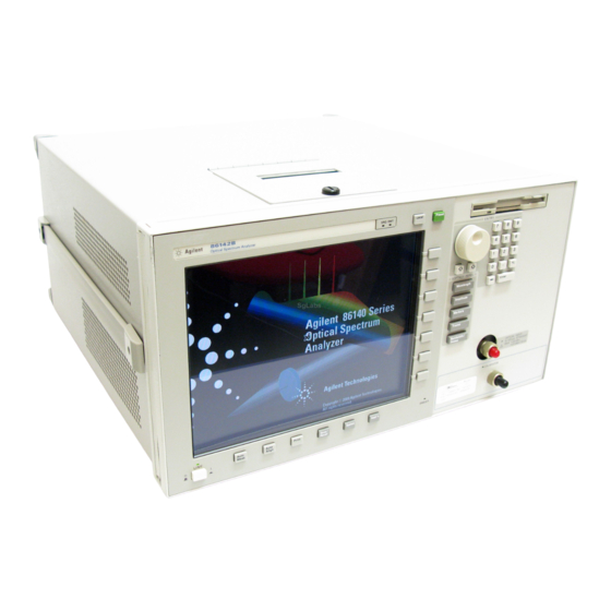
Getting Started Product Overview Product Overview The 86140B series of optical spectrum analyzers provide fast, accurate, and comprehensive measurement capabilities for spectral analysis. • Full-featured SCPI commands for programming instruments over LAN • Display-off feature for making faster measurements • Remote file saving and printing for outputting measurement results •... - Page 10 Getting Started Product Overview Source Test Application This application offers automated optical source and laser characterization. Amplifier Test Application This application simplifies the process of characterizing gain and noise figure of optical amplifiers such as EDFA’s, SOA’s and Raman amplifiers.
- Page 11 Getting Started Product Overview Agilent 86140B Front and Rear Panels...
- Page 12 Getting Started Product Overview...
- Page 13 Getting Started Product Overview Optical Spectrum Analyzer Display Figure 1-1. Optical Spectrum Analyzer Display...
- Page 14 Getting Started Product Overview Figure 1-2. Display Annotations...
-
Page 15: Setting Up The Analyzer
Getting Started Setting Up the Analyzer Setting Up the Analyzer Step 1. Receive and Inspect the Shipment Table 1-1. Items in a Standard Agilent 86140B Series Shipment Item Description Product Number Quantity BNC Cable (24 inches) 8120-1839 GPIB Cable 8120-3444 FC/PC Dust Cap 1401-0291 English User’s Guide Manual... - Page 16 Keep the shipping container and cushioning material until you have inspected the contents of the shipment for completeness and have checked the optical spectrum analyzer mechanically and electrically. If anything is missing or defective, contact your nearest Agilent Technologies Sales Office. Refer to “Returning the Instrument for Service” on page 6-21.
- Page 17 Parallel connector. Use a parallel Centronics printer ca- ble, such as an HP C2950A (2 m) or HP C2951A (3 m). The line cord provided is matched by Agilent Technologies to the country of origin on the order.
- Page 18 Getting Started Setting Up the Analyzer Table 1-2. Line Power Requirements Power 115 VAC: 110 VA MAX. / 60 WATTS MAX. / 1.1 A MAX. 230 VAC: 150 VA MAX. / 70 WATTS MAX. / 0.6 A MAX. Voltage nominal: 115 VAC / 230 VAC range 115 VAC: 90–132 V range 230 VAC: 198–254 V Frequency...
- Page 19 To learn more about this or any Agilent Technologies product, visit our web site at http://www.agilent.com/cm/index.shtml. Or, to learn more about fiber optic test equipment, follow this path from the address listed: 1 Click Communications Products.
-
Page 20: Making A Measurement
Getting Started Making a Measurement Making a Measurement This procedure will introduce you to the Agilent 86140B series optical spec- trum analyzer front panel controls. By following this procedure you will do the following: • Perform an auto alignment • Perform a peak search •... - Page 21 Getting Started Making a Measurement To perform an Auto Align For maximum amplitude accuracy, perform an automatic alignment whenever the optical spectrum analyzer has been moved, subjected to large temperature changes, or following warm-up. See “Auto Align” on page 3-10 for more infor- mation.
- Page 22 Getting Started Making a Measurement To zoom in on the signal Press the Span softkey and then use the knob, step keys, or numeric keypad to zoom in on the signal. Using the delta marker The optical spectrum analyzer has four types of markers; normal markers, bandwidth markers, delta markers and noise markers.
- Page 23 Getting Started Making a Measurement Printing the display 10 Press the Print key to print a copy of the display. The output will be sent to the internal or external printer, depending on the printer selected. 1-16...
-
Page 24: The Menu Bar
Getting Started The Menu Bar The Menu Bar The Menu bar includes the File, Measure, Application, and Options drop-down menus. Each menu selection includes a descriptive label. (Action) Indicates the selection will perform an action such as making a measurement or printing the display. Indicates the selection will open a softkey panel. -
Page 25: The Softkey Panels
Getting Started The Softkey Panels The Softkey Panels You can access the softkey panels using either the front-panel keys or the menu bar. This section includes brief descriptions of the following menus. See Chapter 3, “Function Reference” for additional information on each of the OSA functions. - Page 26 Getting Started The Softkey Panels The Amplitude Menus You can access the Amplitude softkeys using the front-panel Amplitude key or the Measure menu Amplitude selection on the menu bar. 1-19...
- Page 27 Getting Started The Softkey Panels The Applications Menus You can access the Applications (Appl’s) softkeys by using the front-panel Appl’s key or the Applications menu Launch an Installed Application section on the menu bar. For a complete description of the applications, refer to the Agi- lent 86140B Series Measurement Applications User’s Guide that came with your instrument.
- Page 28 Getting Started The Softkey Panels 1-21...
- Page 29 Getting Started The Softkey Panels The Bandwidth/Sweep Menus You can access the Bandwidth/Sweep softkeys by using the front-panel Band- width/Sweep key or the Measure menu Bandwidth/Sweep selection on the menu bar. 1-22...
- Page 30 Getting Started The Softkey Panels The Markers Menus You can access the Markers softkeys by using the front-panel Markers key or the Measure menu Markers selection on the menu bar. 1-23...
- Page 31 Getting Started The Softkey Panels The Save/Recall Menus You can access the Save/Recall softkeys and setup panels by using the drop- down File menu Save/Recall selection or the front-panel Save/Recall key. Use these functions to save, recall and print the measurement results. 1-24...
- Page 32 Getting Started The Softkey Panels The Systems Menus You can access the System softkeys by using the front-panel System key or the Options menu System selection on the menu bar. 1-25...
- Page 33 Getting Started The Softkey Panels The Systems Menus, continued..1-26...
- Page 34 Getting Started The Softkey Panels The Traces Menus You can access the Traces softkeys by using the front-panel Traces key or the Measure menu Traces selection on the menu bar. 1-27...
- Page 35 Getting Started The Softkey Panels The Wavelength Menus You can access the Wavelength softkeys by using the front-panel Wavelength key or the Measure menu Wavelength selection on the menu bar. 1-28...
-
Page 36: Laser Safety Considerations
Getting Started Laser Safety Considerations Laser Safety Considerations N O T E Refer to the Tunable Laser Modules User’s Guide for complete laser safety information. Laser Safety Laser radiation in the ultraviolet and far infrared parts of the spectrum can cause damage primarily to the cornea and lens of the eye. -
Page 37: Product Options And Accessories
Getting Started Product Options and Accessories Product Options and Accessories Options Agilent 86140B, 86141B, Agilent 86143B, 86144B, 86142B, 86146B 86145B Benchtop Portable Instrument System Options Current Source Opt. 001 ---- White Light Source Opt. 002 ---- Built-in 1310 & 1550 nm EELED Source Opt. - Page 38 Getting Started Product Options and Accessories Table 1-3. Accessories Item Option Description Product Number Quantity Connector Accessories HP/HMS-10 Connector Adapter 08154-61701 HMS-10 Dust Cap 1401-0291 FC/PC Connector Adapter 08154-61702 FC/PC Dust Cap 1401-0291 Angled to Flat, FC/PC Adapter 1250-3175 DIN Optical Connector Adapter 08154-61703 DIN Dust Cap 1401-0291...
- Page 39 Options 002, 004, and 005 are exclusive b. Only one option is available on the 86141B Table 1-5. Additional Parts and Accessories Agilent Benchtop OSA Agilent Portable OSA 86140B, 86141B, 86142B, 86143B, 86144B, 86145B 86146B Printer Paper (5 rolls/box) 9270-1370...
- Page 40 Getting Started Product Options and Accessories Front Panel Fiber-Optic Adapters Front Panel Description Agilent Part Number Fiber-Optic Adapter Diamond HMS-10 08154-61701 08154-61702 FC/PC 08154-61708 08154-61703 08154-61704 Biconic 08154-61705 a. The FC/PC is the default front-panel optical connector. 1-33...
- Page 41 Getting Started Product Options and Accessories 1-34...
-
Page 42: Using The Instrument
Setting Up Measurements 2-2 Calibrating Wavelength Measurements 2-14 Saving, Recalling, and Managing Files 2-19 Analyzing Measurement Data 2-27 Analyzer Operating Modes 2-30 Using the Instrument... -
Page 43: Setting Up Measurements
Using the Instrument Setting Up Measurements Setting Up Measurements This section contains the following information that will help you set up a wavelength measurement: • Adjusting Setup Conditions • Operating the Internal White Light Source • Averaging Traces • Setting Video Bandwidth •... - Page 44 Using the Instrument Setting Up Measurements Adjusting Setup Conditions Setup panels allow you to adjust setup conditions which are not frequently changed. Refer to “Preset” on page 3-65. Using the softkeys Arrows allow you to navigate from field to field in the dialog box. The high- lighted parameter can be changed.
- Page 45 Using the Instrument Setting Up Measurements Operating the Internal White Light Source For Option 002 only Option 002 provides a built-in white light source which is a stable, broadband light source for swept-wavelength stimulus response testing from 900 nm to 1700 nm.
- Page 46 Using the Instrument Setting Up Measurements æ ö -- - log A log B – è ø 1 Connect the Light Source Output to the Monochromator Input using the short 62.5/125 µ m fiber. The standard connector interface is FC/PC.
- Page 47 Using the Instrument Setting Up Measurements Averaging Traces Trace averaging improves your measurement repeatability by smoothing out noise. For measurements involving slow polarization scrambling, using video filtering to improve repeatability will require a very narrow video bandwidth (less than 10 Hz). This would result in a long measurement time, where trace averaging would be faster.
- Page 48 Using the Instrument Setting Up Measurements Setting Video Bandwidth Video bandwidth filtering occurs after the detection of the light. In the auto coupled mode, the video bandwidth has an extremely wide range. This allows the instrument to avoid unnecessary filtering that would reduce the sweep speed more than required.
- Page 49 Using the Instrument Setting Up Measurements video bandwidth and sensitivity, it is recommended that either the sensitivity or the video bandwidth be changed, whichever is the most important to the measurement task being performed. To reduce noise, you can select a narrower video bandwidth to improve repeatability and sensitivity or select a wider video bandwidth to shorten over- all measurement time.
- Page 50 Using the Instrument Setting Up Measurements Setting the Sensitivity Setting sensitivity requests the lowest amplitude signal that can be measured relative to the highest amplitude signal displayed. It is defined as the signal that is six times the RMS noise. The minimum setting is –100 dB. An error will be reported for values outside of this range and the sensitivity will round to the nearest valid sensitivity.
- Page 51 Using the Instrument Setting Up Measurements Triggering a Measurement Triggering a measurement synchronizes the start of the sweep to an internally generated trigger signal. Internal triggering ensures continuously triggered sweeps with the shortest delay between sweeps. Refer to “Trigger Mode, Internal”...
- Page 52 Using the Instrument Setting Up Measurements The display will have at least one data sample marked as valid (high level) per trace point. Or else you can use the Max Hold function to complete a trace over several sweeps. Multiple sweeps fill the gaps because the high and low levels of the gating signal occur independent of the grating position.
- Page 53 Using the Instrument Setting Up Measurements Moving the Active Function Area The active function area on the display can be moved to eight different loca- tions. This allows you to place the active area in a location that will not inter- fere with the trace information.
- Page 54 Using the Instrument Setting Up Measurements Indicating an Update is Needed This feature alerts you to take a sweep after changing any sweep related parameters when the analyzer is not in sweep mode. For example, if you change the resolution bandwidth, the new resolution bandwidth is displayed on the bottom of the screen, but the trace data displayed on the screen used the previous resolution bandwidth value.
-
Page 55: Calibrating Wavelength Measurements
Using the Instrument Calibrating Wavelength Measurements Calibrating Wavelength Measurements Environmental variations such as air pressure, temperature, and humidity can affect the index of refraction of air in the monochromator of the optical spec- trum analyzer (OSA). This section discusses calibration methods that you can use to improve the wavelength accuracy in the Agilent 8614X OSA’s. - Page 56 Using the Instrument Calibrating Wavelength Measurements Internal Wavelength Calibration The optional internal calibrator (1513 to 1540 nm) provides a convenient method for increasing wavelength accuracy when used with an internal Enhanced Wavelength Calibration (EWC) process. The wavelength accuracy of the OSA will be ±0.2 nm over the full wavelength range of the instrument, with ±10 pm over 1480 to 1570 nm and ±25 pm accuracy over 1570 to 1620 The EWC range can be selected for either the “full”...
- Page 57 Using the Instrument Calibrating Wavelength Measurements External Single Wavelength Calibration Using an external single-point calibration source allows the calibration to be done at a specific wavelength. This single wavelength user calibration can be repeated as often as necessary to correct for environmental variations and existing multipoint wavelength offsets will be adjusted accordingly.
- Page 58 Using the Instrument Calibrating Wavelength Measurements External Multipoint Wavelength Calibration An external multipoint wavelength calibration can be performed over any specified wavelength range, up to and including the full wavelength range of the OSA (600 nm to 1700 nm). Narrow measurement spans can be chosen to provide greater accuracy over a selected range.
- Page 59 Using the Instrument Calibrating Wavelength Measurements Wavelength Cal Setup and choosing the Offset option before running the single point calibration. To insure this offset process has provided sufficient accuracy, the wavelength readings of the multi-wavelength meter and the OSA should be compared to verify the wavelength accuracy and determine if a full multipoint wavelength recalibration is necessary.
-
Page 60: Saving, Recalling, And Managing Files
Using the Instrument Saving, Recalling, and Managing Files Saving, Recalling, and Managing Files The functions and methods available for saving, recalling, and managing files that contain measurement setups and results are as follows: • Adding a Title to the Display •... - Page 61 Using the Instrument Saving, Recalling, and Managing Files Backing Up or Restoring the Internal Memory 1 Press the front-panel Save/Recall key. 2 Press the Backup/Restore Menu..softkey. N o t e The auto span value will not be saved with the measurement. Refer to “Backup Internal Memory”...
- Page 62 Using the Instrument Saving, Recalling, and Managing Files Save will overwrite any currently existing Fast Save file. N o t e The auto span value will not be saved with the measurement. Saving Measurement and Trace Data 1 Press the front-panel Save/Recall key. 2 Press the Save Menu..
- Page 63 Using the Instrument Saving, Recalling, and Managing Files Save Traces Selects the traces to be saved. Save Graphics Allows you to save graphic data in one of two formats. These selections are valid only when saving to the floppy drive. CGM (Computer Graphics Metafile format) is a vector graphics format that describes pictures and graphical elements in geometric terms.
- Page 64 Using the Instrument Saving, Recalling, and Managing Files Entering a Filename Using the Arrow Keys • Use the front-panel step keys ( Ý and ß ) and the arrow softkeys ( → and ← ) to highlight each letter of the filename. •...
- Page 65 Using the Instrument Saving, Recalling, and Managing Files Recalling Measurement and Trace Data You can recall measurement and trace data using the following methods: • Fast Measurement Recall Mode • Recall Setup Panel Mode Refer to “Recall (Recall Setup Panel)” on page 3-67.
- Page 66 Using the Instrument Saving, Recalling, and Managing Files Recall From Selects whether to recall from a floppy disk or from internal memory. 4 When you are satisfied with your selections, press the Choose File to Recall softkey. The Catalog setup panel opens. The Catalog setup panel 5 Use the arrow keys or Prev File, Next File softkeys to highlight the desired file.
- Page 67 Using the Instrument Saving, Recalling, and Managing Files File Sharing and Printing over a Network This function uses the LAN to print to network printers and store, recall or delete data on remote hard drives. The data can then to be accessed and shared among the users and printed on designated printers.
-
Page 68: Analyzing Measurement Data
Using the Instrument Analyzing Measurement Data Analyzing Measurement Data This section provides advice and information on the following analyzer func- tions that allow you to analyze the measured amplitude wavelength data. • Tips for Using Traces and Markers • Measuring the Delta between Traces •... - Page 69 Using the Instrument Analyzing Measurement Data (2-1) 0.206 nm, -0.002 dB. The color of the annotation denotes different characteristics of the markers: • White annotation denotes the status of the currently active marker. • Green annotation denotes the status of all currently used markers. •...
- Page 70 Using the Instrument Analyzing Measurement Data Using Trace Math to Measure Wavelength Drift 1 From the front panel, press Traces > Active Trace > TrA. 2 Press Single Sweep, Bandwidth Sweep, Single Sweep to update Trace A then press Traces, Update A off. 3 Press Active Trace >...
-
Page 71: Analyzer Operating Modes
Using the Instrument Analyzer Operating Modes Analyzer Operating Modes This section discusses the following analyzer modes that you can use in spe- cific measurement applications. • Filter Mode (For Agilent 86144B/86146B only) • Filter Mode (For Agilent 86141B only) • Time Resolved Chirp Filter Mode For Agilent 86144B/86146B only The Agilent 86144B and 86146B filter mode allows a single channel from a... - Page 72 Using the Instrument Analyzer Operating Modes When the analyzer enters the filter mode, the sweep stops with the analyzer filter tuned to the center wavelength. (If a marker is on, the analyzer filter is tuned to the marker wavelength.) The last trace remains displayed to show the input spectrum before the filtering.
- Page 73 Using the Instrument Analyzer Operating Modes Table 2-6. Differences Between Agilent 86141B and 86144B/86146B µ 86141B Unique Operation (Internal 50 m Fiber Switch) Filter mode initialization: • Previous settings are lost • A single sweep is taken Markers used: • The marker is set to the reference level Functions limited to: •...
- Page 74 Using the Instrument Analyzer Operating Modes Accessing the filter mode (for 86144B/86146B only) N o t e Filter mode will not function in zero span. The filter mode selection will be shaded out. The current state before entering filter mode will not be saved. A sweep will not be taken.
- Page 75 Using the Instrument Analyzer Operating Modes The data returned by the alignment is stored for both the external (9 µ m) and the internal (50 µ m) path. With the data stored for both paths, the alignment for the internal path is improved due to the increased resolution bandwidth of the external path.
- Page 76 Using the Instrument Analyzer Operating Modes N o t e If the file saved in filter mode is recalled into an instrument with firmware revision B.04.02, a critical error occurs, indicating a grating positioning failure. Restart the instrument to clear the error and then continue making measurements.
- Page 77 Using the Instrument Analyzer Operating Modes The light is output from the optical spectrum analyzer’s front panel monochro- mator output connector. This light is a filtered (by the resolution bandwidth) and attenuated (by the monochromator loss) light input to the front panel monochromator input connector.
- Page 78 Using the Instrument Analyzer Operating Modes Time Resolved Chirp For Agilent 86146B option TRC only The Agilent 86146B, with the filter mode capability, will measure side mode suppression ratio (SMSR), wavelength, and power. With the addition of an Agilent 86100 Infinium Digital Communications Analyzer (DCA), dedicated software (86146B Option TRL), and a personal computer, time resolved chirp (TRC) of a modulated laser can be calculated.
- Page 79 Using the Instrument Analyzer Operating Modes 2-38...
-
Page 80: Function Reference
Function Reference... - Page 81 Function Reference Function Reference Function Reference This chapter is an alphabetical reference of front panel keys, softkeys, and setup panel parameters. It is designed for quick information access. For exam- ple, during an operation you may find a key whose function is unfamiliar to you.
- Page 82 Function Reference Active Marker Active Marker Accesses the menu that allows you to select an active marker. Selecting a marker always places that marker on the center wavelength of the active trace. Up to four markers can be simultaneously displayed. If multiple markers are displayed, the active marker appears as a white diamond and the other markers appear as green diamonds.
- Page 83 Function Reference Adv Service Functions Adv Service Functions Accesses the following functions: • Grating Order • More Adv Service Menu • Wavelength Limit • Zero Now Key Path System > More System Functions > Service Menu > Adv Service Functions Advanced Line Mkr Functions Accesses the following functions: •...
- Page 84 Function Reference All Off All Off Turns all the active markers off. N o t e If filter mode is on, this function is not available. Key Path Markers > Active Marker > All Off Remote CALCulate[1|2|3|4|5|6]:MARKer[1|2|3|4]:AOFF Commands Amplitude Accesses the menu of keys that allow you to control the instrument’s sensitiv- ity and amplitude scales.
- Page 85 Function Reference Amplitude Setup Amplitude Setup Accesses the Amplitude Setup panel that allows you to specify amplitude related functions: • amplitude correction mode • amplitude correction sel • amplitude units • auto chop mode • auto ranging • auto zero •...
- Page 86 Function Reference Amplitude Setup Setup Panel Reference Level Position Selections The value selected for the Reference Level Position determines the position of the reference level on the graticule. Setting this value to zero divisions places the reference level on the very bottom of the grid. Setting the reference level to 10 divisions places the reference level at the top of the grid.
- Page 87 Function Reference Amplitude Setup N o t e Turning Auto Zero off allows the instrument to sweep faster, but results in less accuracy on low level signals. The optical spectrum analyzer performs a more complete zeroing when the instrument is first turned on. You can run this more complete routine anytime by pressing the Zero Now softkey.
- Page 88 Function Reference Amplitude Units (Amplitude Setup Panel) When AMPCOR is turned on, the correction points are applied across the active measurement range and added to all measurement results. Between points, the correction values are interpolated linearly or logarithmically. When measuring at wavelengths outside the first and last correction points, the first or last value (as appropriate) is used as the correction value.
- Page 89 Function Reference Auto Align Auto Align Pressing the auto align button on the front panel of the instrument performs an automatic alignment of the instrument using the largest signal found in a full span sweep. This aligns the output of the monochromator with the photo- detector for improved amplitude accuracy.
- Page 90 Function Reference Auto Align & Add to Trajectory Auto Align & Add to Trajectory Allows alignment at several wavelengths, ensuring amplitude accuracy of your measurements. Before initiating the alignment, connect a broadband light source to the front-panel input connector. (You may add and/or update the existing points in the trajectory table.) Press Auto Align Preset to clear the table.
- Page 91 Function Reference Auto Meas broadband or narrowband light source. If there is insufficient signal power, the automatic measurement will not be performed, and a warning message will be reported. This automatic measurement routine is normally the best way to adjust sensitivity while maintaining the fastest sweep rates. The auto measure function uses trace A to perform the measurement.
- Page 92 Function Reference Auto Ranging (Amplitude Setup Panel) N o t e None of the Automeasure Setup parameters are affected by the front-panel Preset key. They are not saved as part of the measurement setup. Key Path Auto Meas Related Functions Auto Align Remote DISPlay[:WINDow[1]]:TRACe:ALL[:SCALe][:AUTO]...
- Page 93 Function Reference Auto Zero (Amplitude Setup Panel) Auto Zero (Amplitude Setup Panel) Turns Auto Zero on and off. Auto Zero on enables the internal amplifiers to be zeroed between sweeps. In this mode, the instrument compensates for tem- perature-related current drift between each sweep. Although this “zeroing” increases amplitude accuracy, it also increases the time between sweeps.
- Page 94 Function Reference Backup Internal Memory Key Path Traces > Averaging Remote CALCulate[1|2|3|4|5|6]:AVERage:COUNt Commands CALCulate[1|2|3|4|5|6]:AVERage:STATe Backup Internal Memory Allows you to make a complete backup of user memory onto a floppy disk. All user files (measurement, trace, and specification sets) are saved. You can recall the backup contents into the instrument with the Restore Internal Mem- ory function.
- Page 95 Function Reference Bandwidth Marker Interpolation (Marker Setup Panel) Bandwidth Marker Interpolation (Marker Setup Panel) Turns the bandwidth marker interpolation on or off. When on, the bandwidth markers will be placed at the exact number of dB (NDB) from the normal marker, if within the trace range.
- Page 96 Function Reference BW Marker Units (Marker Setup Panel) BW Marker Units (Marker Setup Panel) Sets the bandwidth marker X-axis readout for frequency or wavelength when the instrument is in a non-zero span. The available selections are nm, µ m, Ang, GHz, and THz.
- Page 97 Function Reference Calibrator Multi-Pt Align Calibrator Multi-Pt Align Adjusts the mechanical position of the instrument’s internal optical compo- nents ensuring amplitude accuracy of your measurements. Before initiating the alignment, connect the internal calibrator to the front-panel input connec- tor. Refer to “External Multipoint Wavelength Calibration” on page 2-17 The instrument automatically sets the start wavelength at 1490 nm, stop wavelength at 1590 nm, span, and reference level, and then performs a fully automatic, internal auto align.
- Page 98 Function Reference Center Wavelength Step Size (Wavelength Setup Panel) Related Functions Start WL, Stop WL, Span Remote SENSe:WAVelength:CENTer Commands Center Wavelength Step Size (Wavelength Setup Panel) Specifies the center wavelength step size. This is used for incrementing center wavelength using the ↑ and ↓ keys. Key Path Wavelength >...
- Page 99 Function Reference Current Source Setup Current Source Setup Accesses the Current Source Setup panel that allows you to turn on or off the current source, set the current limit, enable pulse width, duty ratio, and syn- chronize the ADC sync output. Refer to “Operating the Internal White Light Source”...
- Page 100 Function Reference Default Math Trace F Default Math Trace F Defines the math expression to be used and turns the math operation on: -D. The result is placed in Trace F. The math operation is performed in linear units. See “Using Trace Math to Measure Wavelength Drift” on page 2-29.
- Page 101 Function Reference Delta Marker On/Off Delta Marker On/Off This toggle function fixes the position of the reference marker and activates the delta marker. This measures the difference between the active (reference) marker and the delta marker. The front knob, step keys, or keypad can be used to move the delta marker to the desired location.
- Page 102 Function Reference Display Mode Display Mode Accesses the choice of log (logarithmic) or lin (linear) data display. Key Path Amplitude > Display mode Remote DISPlay:WINDow:TRACe:Y:SCALe:SPACing LINear|LOGarithmic Commands Display Setup Accesses the display setup panel selections which include: • active function area assist •...
- Page 103 Function Reference Display Setup Title Turns the title on the display. Active Function Area Assist Automatically sets the Active Function Area (when function is turned on) to the first or top softkey. For example, when you press the front-panel Band- width/Sweep key, the Active Function Area Assist function will set the Active Function Area to resolution bandwidth.
- Page 104 Function Reference Exchange Menu Exchange Menu Accesses the trace exchange selections which include: • A Exchange B • B Exchange C • C Exchange A • D Exchange A • E Exchange A • F Exchange A Exchanges the X- and Y-axis data of the two traces. The trace pairs that can be exchanged are Trace A with any trace, and Trace B with Trace C.
- Page 105 Function Reference Fast Meas Recall Fast Meas Recall Accesses the fast measure recall function that recalls the measurement state previously saved as FASTSAVE.dat in the internal memory by the Fast Mea- sure Save function. Refer to “Recalling Data in Fast Meas Recall Mode” on page 2-24 Key Path Save/Recall >...
- Page 106 Function Reference File Shares When Manual is selected, pressing the Choose File to Save softkey will access the Filename Menu setup panel. Use the front panel step keys, knob, or arrow softkeys to highlight and then select each letter in the filename. Filenames can also be set with an external keyboard, Refer to “Entering a Filename using an External Keyboard”...
- Page 107 Function Reference Filter Marker Tune Filter Marker Tune For Agilent 86144B/86146B Filter Mode only. Tunes the wavelength of the preselector. During the preselector instrument mode, the instrument acts as an optical filter at a fixed wavelength. Although the instrument is not sweeping the displayed input range, the last sweep remains displaying the input spectrum.
- Page 108 Function Reference Filter Mode Filter Mode For Agilent 86141B only Accesses the filter mode function. Refer to “Filter Mode” on page 2-30 Appl’s > Measurement Modes > Filter Mode Key Path Remote INSTrument:SELect “FILTER” Commands Filter Mode For the Agilent 86144B/86146B Filter Mode only. The filter mode utilizes the 9 µ...
- Page 109 Function Reference Firmware Upgrade Firmware Upgrade The instrument will restart into a utility to upgrade the instrument firmware. For upgrade instructions, or to order a firmware upgrade kit, visit or web site at http://www.agilent.com/cm/rdmfg/osa/downloads/ 8614xafirmware.shtml. Key Path System > More System Functions > Service Menu > Firmware Upgrade Format Floppy Disk Formats a 3.5, 1.44 MB floppy disk.
- Page 110 Function Reference GPIB Address GPIB Address Accesses the GPIB address information. To change the address, use the numerical entry keys, step keys, or knob to enter the new GPIB address infor- mation. If changes are made, press the Select softkey. Press the Defaults soft- key to reset the address to the factory preset default, 23.
- Page 111 Function Reference Hold A...F None Min Max (trace) Hold A...F None Min Max (trace) Hold Max compares the current amplitude value of each point on the active trace in the current sweep to the corresponding point detected during the previous sweep, then displays the maximum value. Hold Min compares the current amplitude value of each point on a trace in the current sweep to the corresponding point detected during the previous sweep, then displays the minimum value.
- Page 112 Function Reference Light Source Light Source Turns the desired light source on or off. The number and type of sources dis- played depends on the options installed. Refer to “Operating the Internal White Light Source” on page 2-4 Key Path System >...
- Page 113 Function Reference Lin Math C=A–B Lin Math C=A – Subtracts Trace B from Trace A point by point, then stores the results in Trace C in linear units. If Trace A is in View On mode, this function is continuous and occurs every sweep.
- Page 114 Function Reference Log Math C=A–B Remote GPIB GoTo Local Command Commands Log Math C=A – Subtracts Trace B from Trace A point by point, then stores the results in Trace C in logarithmic units. If Trace A is in View On mode, this function is continu- ous and occurs every sweep.
- Page 115 Function Reference Log Math F=C–D Log Math F=C – Subtracts Trace D from Trace C point by point, then stores the results in Trace F in logarithmic units. If Trace C is in View On mode, this function is continu- ous and occurs every sweep.
- Page 116 Function Reference Marker BW Marker BW Measures the passband of the signal. To enter the bandwidth amplitude of the bandwidth markers, make a selection from the softkeys (–3 dB, –6 dB, –10 dB, and –20 dB) or use the knob, step keys, or numeric keys.
- Page 117 Function Reference Marker Search Menu Marker Search Menu Accesses the following marker peak and pit search functions: • peak or pit search mode • peak or pit search • next peak down, left or right • next pit up, left or right •...
- Page 118 Function Reference Marker Setup Marker Setup Accesses a menu that allows you to make changes to default marker settings. From the setup panel you can make changes to: • Bandwidth/Marker Interpolation On|Off • BW Marker Units • Delta Marker Units •...
- Page 119 Function Reference Marker Setup Setup Panel Normal Marker Units Selections Sets the X-axis immediately displayed marker information for frequency or wavelength when the instrument is in a non-zero span. This setting controls only the normal marker X-axis and the delta reference immediately displayed information.
- Page 120 Function Reference Marker Setup Peak Excursion Determines (in dB) which side modes are included in the measurements. To be accepted, each trace peak must rise, and then fall, by at least the peak excursion value about a given spectral component. The default value is 3 dB. Setting the value too high may result in not identifying a side mode.
- Page 121 Function Reference Marker Setup Changing the pit excursion. The pit searches may not recognize valid sig- nals near the noise floor when the pit excursion definition is less than 3 dB. Thus, before performing pit searches on signals near the noise floor, reduce the pit excursion value.
- Page 122 Function Reference Marker to Center æ ö ------------ - è ø • Manual: Uses a user specified fix offset from the center marker. The default value is 0.4 nm and the step size is 0.2 nm when using the step keys. This field is inactive when set to Auto or Pit.
- Page 123 Function Reference Markers Marker Tune For Agilent 86141B only Tunes the wavelength of the preselector. During the preselector instrument mode, the instrument acts as an optical filter at a fixed wavelength. The out- put is available at the front panel Monochromator connector. Although the instrument is not sweeping the displayed input range, the last sweep remains displayed in order to show the input spectrum.
- Page 124 Function Reference More Marker Functions Measurement Mode For Agilent 86141B/86144B/86146B only Accesses filter mode and power meter mode. Key Path Appl’s > Measurement Modes Related Functions Filter mode, Power Meter mode Remote INSTrument:NSELect Commands INSTrument:SELect More Marker Functions Accesses the following marker search functions: •...
- Page 125 Function Reference Move Active Area Move Active Area Moves the active function area to one of eight on-screen locations. To change the active function area location, press the Move Active Area softkey until you are satisfied with the position. Key Path System >...
- Page 126 Function Reference New GPIB Address (Remote Setup Panel) New GPIB Address (Remote Setup Panel) Allows you to enter a new GPIB address. To change the address, use the numeric entry keys, step keys, or knob. Press the Defaults softkey to reset the address to the factory preset default, 23.
- Page 127 Function Reference Next Peak Right → → Next Peak Right Places the marker on the next peak located at a higher X-axis value (usually wavelength) than the current marker position. This peak must meet the peak excursion and threshold criteria. If the specified marker is off, it will be turned on and placed at the center wavelength or frequency.
- Page 128 Function Reference Next Pit Up ↑ ↑ Next Pit Up Places the active marker on the next lowest pit from the current marker amplitude. This pit must meet the pit excursion and threshold criteria. If the specified marker is off, it will be turned on and placed at the center wave- length.
- Page 129 Function Reference Normal/Delta Marker Interpolation (Marker Setup Panel) Normal/Delta Marker Interpolation (Marker Setup Panel) Turns the normal/delta marker interpolation on or off. When on, the normal/ delta markers will be placed at the exact wavelength or frequency value selected if it is within the trace range. The marker will linearly interpolate between two trace data points.
- Page 130 Function Reference OSNR Marker OSNR Marker Indicates the signal quality based on the signal strength and noise level. Turn- ing on the OSNR marker will display four markers: an active marker, a center marker, and two noise markers. To adjust the active marker to the desired measurement location, use the step keys, knob, or keyboard.
- Page 131 Function Reference OSNR Marker Center amplitude OSNR = --------------------------------------------------- - normalized Interpolating Noise To accurately measure noise, the noise level must be determined at the signal wavelength. The measurement cannot be directly performed because the sig- nal power level masks the noise. To estimate the noise at the signal wave- length, the OSA measures the noise power above and below the channel wavelength at the predetermined offset or pits (depending on the Noise Method selected in the Marker Setup panel).
- Page 132 Function Reference OSNR Marker Noise Not Found error message Tip: If this error occurs, decrease the pit excursion (when you are in pit mode), increase the span (when you are in auto or manual mode), or select manual (when you select auto mode) to adjust the offset. Center Not Found and OSNR Not Valid occurs if no signal or peaks are found.
- Page 133 Function Reference OSNR Marker Center Not Found error message Key Path Markers > More Marker Functions > OSNR Marker Remote CALCulate[1|2|3|4|5|6]:MARKer[1|2|3|4]:FUNCtion:OSNR[:STATe} Commands OFF|ON|0|1 3-54...
- Page 134 Function Reference Options Options Accesses the Current Source Setup and Light Source Output Setup softkeys. Current Source Setup panel allows you to set the current limit, enable pulse mode and synchronize the ADC sync output. See “Current Source Setup” on page 3-20 Light Source panel turns the desired light source on or off.
- Page 135 Function Reference OSA State OSA State Displays the state information. The state information includes: • center wavelength • model # • options • serial # • software revision • span • start wavelength • stop wavelength • wavelength offset • wavelength step You can print this information using the internal or external printer.
- Page 136 Function Reference Peak to Center Peak to Center Finds the highest amplitude trace point and sets the center wavelength to that wavelength. Key Path Wavelength > Peak to Center Remote CALCulate[1|2|3|4|5|6]:MARKer[1|2|3|4]:MAXimum Commands CALCulate[1|2|3|4|5|6]:MARKer[1|2|3|4]:SCENter SENSe:WAVelength:CENTer Peak Excursion (Marker Setup Panel) Sets the peak excursion value for the marker search functions. Peak excursion criteria For marker search functions, a signal peak is defined as a rise and fall in the displayed response by at least the peak excursion value.
- Page 137 Function Reference Peak Search Peak Search Places a marker on the highest amplitude trace point. If no marker is on, Marker #1 will be used for the peak search. Next Peak Down Places the marker on the next highest peak from the current marker ampli- tude.
- Page 138 Function Reference Peak Search at End of Each Sweep (Marker Setup Panel) Key Path Markers > Peak Search Markers > More Marker Functions > Marker Search Menu > Search Mode Peak > Peak Search Remote CALCulate[1|2|3|4|5|6]:MARKer[1|2|3|4]:MAXimum Commands Peak Search at End of Each Sweep (Marker Setup Panel) Finds the peak value of the trace and moves the active marker to the peak at the end of each sweep.
- Page 139 Function Reference Perform Calibration Perform Calibration Performs a power or wavelength calibration after the setup has been specified by the user. Key Path System > Calibration > Power Cal Setup > Perform Calibration Remote CALibration:WAVelength:INTernal Commands Pit Excursion (Marker Setup Panel) Sets the pit excursion value for the marker search routines.
- Page 140 Function Reference Pit Search Pit Search Places a marker on the lowest amplitude trace point which meets the pit excursion criteria. If no marker is on, Marker #1 will be used for the pit search. Key Path Markers > More Marker Functions > Marker Search Menu > Search Mode Pit >...
- Page 141 Function Reference Power Calibration Setup Power Display For 86141B/86144B/86146B only In Power Meter mode, turns power display on or off. Key Path Appl’s > Measurement Modes > Power Meter Mode > Power Display Remote DISPlay[:WINDow[1]]:POPup[1|2|3|4][:ALL] OFF|ON|0|1 Commands Power Meter Mode For 86141B/86144B/86146B only Power meter operation is an operation mode available on the 86141B/86144B/ 86146B instruments.
- Page 142 Function Reference Power Calibration Setup Key Path Appl’s > Measurement Modes > Power Meter Mode Remote INSTrument:SELect? Commands INSTrument:NSELect Power Meter Zero For Agilent 86141B/86144B/86146B only Zero’s the power meter detector to provide more accurate measurements. Key Path Appl’s > Measurement Modes > Power Meter Mode > Power Meter Zero Related Functions Power display Power meter mode...
- Page 143 Function Reference Power On State IP/Last Power On State IP/Last Selects the state, IP or Last, of the instrument when it is turned on. The default state is IP. If IP is selected, the instrument will turn on in a known, preset state. With the settings as they would be after pressing the front-panel Preset key.
- Page 144 Function Reference Preset Preset Resets the instrument to a known preset state. Selecting preset aborts any current operations and clears the GPIB output queue. Preset leaves some set- tings in place, for example, the title on the display. Table 3-7. Default values Preset Preset Function...
- Page 145 Function Reference Print Preset Preset Function Function Value Value Marker 1–4 Marker 1–4 bandwidth Marker 1–4 bandwidth –3 dB Marker 1–4 delta amplitude Marker 1–4 noise Marker 1–4 delta marker units Current trace Trace integration Trace integration limit Trace mean Trace mean limit Trace average count ASCII...
- Page 146 Function Reference Printer Setup Printer Setup Accesses the printer setup panel that allows you to select either the internal printer or external printer as the print destination. Key Path System > Printer Setup Remote HCOPy:DESTination Commands Printer Shares Uses the LAN (local area network) to print data to network printers. The data can be printed on designated, PCL3 format or newer printers.
- Page 147 Function Reference Recall From (Recall Setup Panel) When Trace(s) Only is selected, the trace data is displayed under the current instrument conditions. N o t e To insure accurate measurements, a wavelength calibration should be performed each time measurement is recalled from memory. Save/Recall >...
- Page 148 Function Reference Recall Menu Recall Menu Accesses the Recall Setup panel for the following settings: • Recall (all measurement data or trace data only) • Recall From (recall from a floppy disk or from the internal drive • Network File Share 1|2|3|4 •...
- Page 149 Function Reference Reference Level Position (Amplitude Setup Panel) Reference Level Position (Amplitude Setup Panel) Determines the position of the reference level on the graticule. Setting this value to zero divisions places the reference level on the very bottom of the grid.
- Page 150 Function Reference Remote Printer Share Panel Remote MMEMORY:FSHAre [1|2|3|4][:PATH] <param> Commands MMEMORY:FSHAre [1|2|3|4][:ADDRess]<param> Remote Printer Share Panel Uses the LAN (local area network) to print to designated, network printers. See “Recalling Measurement and Trace Data” on page 2-24 N o t e To access the file and printer share softkeys, you must first configure the network and enter the user share identity/user profile information for remote shares.
- Page 151 • For 86140B Option 025, 86143B option 025, 86141B: 0.07 nm, 0.1 nm, 0.2 nm, 0.3 nm, 0.5 nm, 1 nm, 2 nm, 5 nm, 10 nm. • For 86140B, 86142B, 86143B, 86145B: 0.06 nm, 0.1 nm, 0.2 nm, 0.3 nm, 0.5 nm, 1 nm, 2 nm, 5 nm, 10 nm.
- Page 152 Function Reference Reset Min/Max Hold Reset Min/Max Hold Resets trace hold data and returns to the Traces function keys where you can select an active trace, trace input, update, view, and hold functions. Key Path Traces > Hold (trace) > Reset Min/Max Hold Remote CALCulate[1|2|3|4|5|6]:MAXimum:CLEar Commands...
- Page 153 Function Reference Save (Save Setup Panel) Save (Save Setup Panel) Selects whether all measurement data or only trace data will be saved. “Saving Measurement and Trace Data” on page 2-20. When Measurement (All Visible + State) is selected, all instrument conditions will be saved.
- Page 154 Function Reference Save Graphics (Save Setup Panel) Save Graphics (Save Setup Panel) Saves graphic data in CGM or GIF format. The CGM (Computer Graphics Metafile) format is a vector graphics format that describes pictures and graphical elements in geometric terms. The GIF (Graphics Interchange format) is a cross platform graphic standard.
- Page 155 Function Reference Save Setup The Save Setup panel Setup Panel File Name Selections Selects manual or automatic mode for choosing a file name. The Filename Menu setup panel Network File Path Uses the LAN (local area network) to print to designated, network printers. 3-76...
- Page 156 Function Reference Save Setup N o t e To access the file and printer share softkeys, you must first configure the network and enter the user share identity/user profile information for remote shares. The softkeys for file and printer share will then become available for selection.
- Page 157 Function Reference Save/Recall Key Path Save/Recall > Save Menu Remote (Graphics format) HCOPy:DEVice:LANGuage Commands (Measurement) *SAV (Trace only) MMEMory:STORe:TRACe (Network File Share)MMEMory:FSHAre [1|2|3|4][:PATH] <param> (Network File Share)MMEMory:FSHAre [1|2|3|4][:ADDRess] <param> (Network File Path)HCOPy:DEVice:PSHare[1|2|3|4][:PATH] <param> (Network File Path)HCOPy:DEVice:PSHare[1|2|3|4]:ADDRess <param> (Network File Path)HCOPy:DESTination”SYSTem:COMMunicate:NET- Work[1|2|3|4] Save/Recall Accesses function keys to save and recall measurement results.
- Page 158 Function Reference Save Traces (Save Setup Panel) Save Traces (Save Setup Panel) Selects the traces to be saved. Select Save Traces and then select the individ- ual trace(s) or all the current trace data. See “Saving Measurement and Trace Data” on page 2-20 Key Path Save/Recall >...
- Page 159 Function Reference Search Limit On/Off Search Limit On/Off When the search limit function is on, all the marker peak/pit searches will apply only to the range specified by the two wavelength line markers. Key Path Markers > More Marker Functions > Line Marker Menu > Advanced Line Mkr Functions >...
- Page 160 Function Reference Select Path INT/EXT Select Path INT/EXT For 86144B/86146B only. Allows you to select between internal (50 µ m) and external (9 µ m) fiber. The dual fiber outputs from the monochromator allow the instrument to have improved resolution bandwidth and dynamic range when using the 9 µ m fiber. The 50 µ...
- Page 161 Function Reference Set Time/Date An increase in sensitivity may also require a narrower video bandwidth, which will slow the sweep speed. Normally, the optical spectrum analyzer selects the greatest sensitivity possible that does not require amplification changes dur- ing the sweep. If you manually increase the sensitivity level, the sweep pauses to allow this change in gain.
- Page 162 Function Reference Set Title Set Title Accesses the Title Setup panel to add a title to the display. Use the softkeys to change or select the items from the setup panel. Refer to “Adding a Title to the Display” on page 2-19 Key Path System >...
- Page 163 Function Reference Show HW Errors Show HW Errors Opens a window displaying hardware errors. You can print the queue, clear the queue, or page up and down to view the information. If no errors are gen- erated, the function will be shaded. Key Path System >...
- Page 164 Function Reference Show Warnings Show Warnings Opens a window displaying warnings. You can print the queue, clear the queue, or page up and down to view the information. If no warnings are gener- ated, the function will be shaded. Key Path System >...
- Page 165 Function Reference Single Sweep Remote INSTrument:SELect Commands Single Sweep Initiates one sweep of the measurement range. Use this function to update the displayed measurement data. Refer to “Repeat Sweep” on page 3-71 Trigger conditions must be met in order for a single sweep to occur. The SWEEP indicator light on the front panel is on when the sweep is in progress.
- Page 166 Function Reference Start WL If you increase the span around a center wavelength beyond one of the end wavelength limits, the center wavelength will change to a value that will allow the span to increase. For example, if the center wavelength is set to 1680 nm and you increase the span to 100 nm, the center wavelength changes to 1650 nm in order to be able to accommodate the 100 nm span.
- Page 167 Function Reference Sweep Points Span Stop Center ------------ - Use the knob, step keys, or numeric keys to enter the desired value. If the instrument is in zero span, this command sets the center wavelength to the value specified. The default for stop wavelength is 1700 nm. Key Path Wavelength >...
- Page 168 Function Reference Sweep Time Sweep Time Specifies the amount of time required for the instrument to sweep the current measurement range. The instrument automatically selects sweep times based on coupling of the following instrument settings: • wavelength span • resolution bandwidth •...
- Page 169 Function Reference Switch Path Auto Align Now Switch Path Auto Align Now For 86144B/86146B Filter Mode only. Switches to the 9 µ m filter mode path and performs an Auto Align. To ensure maximum amplitude accuracy, connect the 9 µ m fiber between the monochro- mator output and the photodetector input and then press Switch Path Auto Align Now.
- Page 170 Function Reference Switch Path No Auto Align Switch Path No Auto Align For 86144B/86146B Filter Mode only. Selects the 9 µ m filter mode path. You should select this function if the instru- ment has not be moved, subjected to temperature changes >2 ° C, turned off and warmed up for at least an hour at the start of each day or to preserve pre- vious align data.
- Page 171 Function Reference Take Sweep Take Sweep For 86141B/86144B/86146B Filter Mode only. Initiates a single sweep that updates the display to show the valid waveform data. Refer to “Repeat Sweep” on page 3-71 and to “Single Sweep” on page 3-86. Key Path Appl’s >...
- Page 172 Function Reference Trace C Math Off When the number of sweeps taken is less than the count, the following for- mula is used to calculate the data: sum of current sweeps ---------------------------------------------------------------------------- - number of averages selected If the number of sweeps is greater than or equal to the count, the following formula is used to calculate the data: æ...
- Page 173 Function Reference Trace Integ Trace Integ Calculates total power. Total power is the summation of the power at each trace point, normalized by the ratio of the trace point spacing and the resolu- tion bandwidth. The analyzer can only calculate the total power of single trace.
- Page 174 Function Reference Trace OffSet Remote CALCulate[1|2|3|4|5|6]:MATH:STATe Commands CALCulate[1|2|3|4|5|6]:MATH:EXPRession:DEFine TRACe:EXCHange Trace OffSet Offsets the active trace by the user-specified value. Key Path Traces > Trace Math Off > Remote Commands CALCulate[1|2|3|4|5|6]:OFFSet Traces Accesses the menu that allows you to select and control traces. Some of the functions available are: •...
- Page 175 Function Reference Trigger Mode, Internal Remote [SENSe]:POWer:RANGe:LOCK Commands Trigger Mode, Internal Synchronizes the start of the sweep to an internally generated trigger signal. Internal triggering ensures continuously triggered sweeps with the shortest delay between sweeps. See “Triggering a Measurement” on page 2-10 Key Path Bandwidth/Sweep >...
- Page 176 Function Reference User Profile for Remote Shares Related Functions Pit Excursion, Peak Excursion, Marker Threshold Value Remote CALCulate:THReshold:STATe Commands User Profile for Remote Shares Accesses the username, password, and workgroup fields for access to your network. Use the alphanumeric pad to complete the information. After enter- ing the information, the file shares and printer shares softkeys will become available.
- Page 177 Function Reference User Source Multi-Pt Align User Source Multi-Pt Align Adjusts the mechanical position of the instrument’s internal optical compo- nents ensuring amplitude accuracy of your measurements. This function is semi-automatic and aligns equally spaced points within the span and builds the current fiber trajectory table.
- Page 178 Function Reference User Wavelength Cal Date Remote CALibration:ALIGn:EXTernal Commands User Wavelength Cal Date Shows the date and time of the last successful user-performed wavelength cal- ibration. Key Path Wavelength > Wavelength Setup > User Wavelength Cal Date Related Functions Wavelength Calibration Video BW Specifies the bandwidth of the post-detection video filter.
- Page 179 Function Reference View (trace) Key Path Bandwidth/Sweep > Video BW Related Functions Sensitivity Remote [SENSe]:BANDwidth|BWIDth:VIDeo:AUTO Commands [SENSe]:BANDwidth|BWIDth:VIDeo View (trace) Allows trace A, B, C, D, E, or F data to be viewed. Viewed traces are not updated as sweeps occur unless the Update function is on. Key Path Traces >...
- Page 180 Function Reference Wavelength Cal Setup Key Path System > Calibration > Wavelength Cal Setup Related Functions Wavelength > Calibration Remote CALibrate:WAVelength:DATE? Commands Wavelength Cal Setup See “Calibrating Wavelength Measurements” on page 2-14. Accesses the fol- lowing: • calibration data will be offset or replaced •...
- Page 181 Function Reference Wavelength Line Mkr 1/2 Signal Source Selects either an external single wavelength signal source or the internal cali- brator as the wavelength calibration source. Wavelength Referenced In (for external calibration source only) Selects air or vacuum for the calibration. If the internal calibrator is selected, this selection will not be available.
- Page 182 Function Reference Wavelength Offset Mkr 1| 2 Remote (Wavelength Line Marker 1):CALCulate[1|2|3|4|5|6]:MARKer[1|2|3|4] Commands :SRANge:LOWer (Wavelength Line Marker 2):CALCulate[1|2|3|4|5|6]:MARKer[1|2|3|4] :SRANge:UPPer (Sweep Limit):SENSe:WAVelength:SRANge:UPPer Wavelength Offset Specifies the wavelength offset. This is an offset between the measured wave- length and the displayed wavelength. You can calibrate the TLS with a wave meter and correct for any offset.
- Page 183 Function Reference Wavelength Units Wavelength Units Sets the display wavelength units to nm, µ m, or Ang. Angtrom (Ang) is a unit of measurement of wavelength of light and other radi- ation equal to one ten-thousandth of a micron or one hundred-millionth of a centimeter.
- Page 184 “Information and Equipment Required for the Configuration Process” on page 4-2 “Setting Up the OSA for Remote Operation” on page 4-4 “Connecting to the OSA over the Network” on page 4-6 “Using the Reflection X Emulator to Run the Remote Front Panel” on page 4-7 “Using the X Win 32 Emulator to Run the Remote Front Panel”...
-
Page 185: Remote Front Panel Operation
Remote Front Panel Operation Remote Front Panel Remote Front Panel The Remote Front Panel capability provides a means to allow the front panel of the OSA to be operated remotely from a PC with an X Windowing emulator or a UNIX workstation with X Windows. With the exception for update time, which is limited by the speed of the underlying network, there should be no visible difference between what would be displayed on the OSA locally and the remote display. - Page 186 Remote Front Panel Operation Remote Front Panel Domain Name System (DNS) Server IP Address is used to uniquely iden- tify the location of a particular server. An IP address is a set of four decimal numbers, separated by periods, like 192.170.130.215. Worksheet for your IT department Internet Protocol (IP) a ddress:________________________________________ Host Name associated with the IP address:______________________________...
-
Page 187: Setting Up The Osa For Remote Operation
Remote Front Panel Operation Remote Front Panel Setting Up the OSA for Remote Operation 1 From the OSA’s front panel, press System > More System Functions > GPIB & Network Setup > Configure Network. 2 When the Network Configuration screen is displayed, press Continue. The OSA will now restart the operating system and load the Network Configure utility. - Page 188 Remote Front Panel Operation Remote Front Panel OK. Press Yes if the address is correct. 14 When prompted to enter additional network parameters, press Yes. 15 Enter the Subnetwork Mask and Gateway IP Address then press OK. If the parameters are correct, press Yes. 16 Enter the Domain Name System and DNS Server IP Address then press OK.
-
Page 189: Connecting To The Osa Over The Network
Remote Front Panel Operation Remote Front Panel Connecting to the OSA over the Network You can remap the OSA front panel over the network using a PC with an X windowing emulator or a UNIX workstation running X Windows. The following X windowing emulators have been tested to ensure correct OSA remote front panel operation. -
Page 190: Using The Reflection X Emulator To Run The Remote Front Panel
Remote Front Panel Operation Remote Front Panel Using the Reflection X Emulator to Run the Remote Front Panel Below are the basic steps for setting up the Reflection X emulator to run the OSA remote front panel. Refer to the Reflection X documentation for further information. - Page 191 Remote Front Panel Operation Remote Front Panel a In the Client Connection area (left side of the window), select hpux.rxc. b In the Method field, select Telnet. c In the Host Name field, select the name assigned to the OSA. d In the User Name field, enter osaadm.
-
Page 192: Using The X Win 32 Emulator To Run The Remote Front Panel
Remote Front Panel Operation Remote Front Panel Using the X Win 32 Emulator to Run the Remote Front Panel Below are the basic steps for setting up the X Win 32 emulator to run the OSA remote front panel. Refer to the X Win 32 documentation for further informa- tion. - Page 193 Remote Front Panel Operation Remote Front Panel 4 In the New Session enter the following information: a In the Session name field, enter a name to uniquely identify the OSA. N o t e An advantage when using the X Win 32 emulator is that you can run multiple X applications on your desktop in separate windows.
- Page 194 Remote Front Panel Operation Remote Front Panel 5 From the PC, Start menu, click X-Win 32 > X Win 32. You will notice that an X icon will appear in your windows tray -- usually located in the lower right-hand part of your display. 6 Click on the X icon and select the desired OSA session to run the remote front panel operation.
-
Page 195: Using A Unix Workstation To Run The Remote Front Panel
Remote Front Panel Operation Remote Front Panel Using a UNIX Workstation to Run the Remote Front Panel In order to access the remote front panel from your UNIX workstation, the X server must be set up to allow connection to the OSA. xhost is the service access control program which allows this access for X Windows. - Page 196 Remote Front Panel Operation Remote Front Panel N o t e Once you changed the password, you will need to remember it for future use. You will not be able to access the remote front panel capabilities without the new password. 7 From the command prompt, type Enable and then press Enter.
- Page 197 Remote Front Panel Operation Remote Front Panel 10 When you are finished using the remote front panel, in the Map Display window, type Disable. The OSA will reboot into normal mode with the remote front panel turned off. The OSA display will close on the PC. 4-14...
-
Page 198: Using The Remote Front Panel
Remote Front Panel Operation Remote Front Panel Using the Remote Front Panel 1 In the Map Display window, a Welcome screen is displayed and you are given three command choices, • Display accesses a diagnostic tool to show the display parameter setup •... - Page 199 Remote Front Panel Operation Remote Front Panel 3 You can now use the remote front panel just like you would if you were sitting in front of the OSA. Remember to use the main menu bar to access OSA functions and to enter data via the keyboard number keys. 4 When you are finished using the remote front panel, in the Map Display window, type Disable.
- Page 200 Overview 5-2 Error Reporting Behavior 5-4 SCPI-Defined Errors 5-5 OSA Notices 5-16 OSA Warnings 5-17 Application-Specific Warnings 5-29 OSA Status Errors 5-35 OSA Errors 5-36 Firmware Errors 5-38 Status Listings...
-
Page 201: Status Listings Overview
Indicates the instrument is malfunctioning. Measurement accuracy is probably affected. Errors can be caused by either a hardware or a firmware problem. The instrument requires repair at a Agilent Technologies service center. Status error Indicates an internal hardware function is unavailable or not operating within specifications. - Page 202 Status Listings Overview The following table lists the error numbers and their definitions. Number Range Definition –1 to –999 Standard SCPI errors 1000 to 2999 OSA notices 3000 to 4999 Application specific notices 5000 to 7999 OSA warnings 8000 to 9999 Application specific warnings 10000 to 11999 OSA status errors...
-
Page 203: Error Reporting Behavior
Status Listings Error Reporting Behavior Error Reporting Behavior Errors are displayed in an on-screen dialog box. To continue operation, the user must acknowledge the error by pressing a button. Status errors are displayed with a descriptive line in the lower-left corner of the graticule. -
Page 204: Scpi-Defined Errors
Status Listings SCPI-Defined Errors SCPI-Defined Errors These error messages and descriptions were copied from the SCPI 1997 Vol- ume 2: Command reference. The sentences enclosed in brackets “[ ]” are copied from the error descriptions in the SCPI reference. References are also made to IEEE 488.2 sections for further clarification of events. - Page 205 Status Listings SCPI-Defined Errors Contact: The Institute of Electrical and Electronics Engineers, Inc. 345 East 47th Street New York, New York 10017-2394 Phone: (800) 678-IEEE (US) 8 a.m. – 4:30 p.m. (EST) (908) 981-1393 (International) Fax: (908) 981-9667 Standard SCPI errors (–1 to –999) All positive numbers are instrument-dependent.
- Page 206 Status Listings SCPI-Defined Errors listening formats or whose type is unacceptable to the device. • An unrecognized header was received. Unrecognized headers include incorrect device-specific headers and incorrect or unimplemented IEEE 488.2 common commands. • A Group Execute Trigger (GET) was entered into the input buffer inside of an IEEE 488.2 <PROGRAM MESSAGE>.
- Page 207 Status Listings SCPI-Defined Errors Table 5-1. Command Errors (2 of 4) Error Number Error Description [description/explanation/examples] –108 desc = “Parameter not allowed” help = ““ [More parameters were received than expected for the header; for example, the *EMC common command only accepts one parameter, so receiving *EMC 0,1 is not allowed.] –109 desc = “Missing parameter”...
- Page 208 Status Listings SCPI-Defined Errors Table 5-1. Command Errors (3 of 4) Error Number Error Description [description/explanation/examples] –128 desc = “Numeric data not allowed” help = ““ [A legal numeric data element was received, but the device does not accept one in this position for the header.] –131 desc = “Invalid suffix”...
- Page 209 Status Listings SCPI-Defined Errors Table 5-1. Command Errors (4 of 4) Error Number Error Description [description/explanation/examples] –161 desc = “Invalid block data” help = ““ [A block data element was expected, but was invalid for some reason (see IEEE 488.2, 7.7.6.2); for example, an END message was received before the length was satisfied.] –168 desc = “Block data not allowed”...
- Page 210 Status Listings SCPI-Defined Errors Execution errors An <error/event number> in the range [–299, –200] indicates that an error has been detected by the instrument’s execution control block. The occurrence of any error in this class shall cause the execution error bit (bit 4) in the event status register (IEEE 488.2, section 11.5.1) to be set.
- Page 211 Status Listings SCPI-Defined Errors Table 5-2. Execution Errors (2 of 3) Error Number Error Description [description/explanation/examples] –222 desc = “Data out of range” help = “A numeric value was entered which is outside the legal range of values for the parameter. The name of the parameter is listed at the end of the error message.”...
- Page 212 Status Listings SCPI-Defined Errors Table 5-2. Execution Errors (3 of 3) Error Number Error Description [description/explanation/examples] –273 desc = “Illegal macro label” help = ““ [Indicates that the macro label defined in the *DMC command was a legal string syntax, but could not be accepted by the device (see IEEE 488.2, 10.7.3 and 10.7.6.2);...
- Page 213 Status Listings SCPI-Defined Errors 488.2, section 11.5.1) to be set. Events that generate device-specific errors shall not generate command errors, execution errors, or query errors; see the other error definitions in this section. Table 5-3. Device-Specific Errors Error Number Error Description [description/explanation/examples] –310 desc = “System error”...
- Page 214 Status Listings SCPI-Defined Errors Table 5-4. Query Errors Error Number Error Description [description/explanation/examples] –400 Query error [This is the generic query error for devices that cannot detect more specific errors. This code indicates only that a Query Error as defined in IEEE 488.2, 11.5.1.1.7 and 6.3 has occurred.] –410 Query INTERRUPTED...
-
Page 215: Osa Notices
Status Listings OSA Notices OSA Notices System control-related error messages or warnings The OSA system changed a setting and generated a warning that the opera- tion was performed. Table 5-5. System Control Errors or Warnings Error Number Error Description [description/explanation/examples] 1000 desc = “Sensitivity forced to Auto”... -
Page 216: Osa Warnings
Status Listings OSA Warnings OSA Warnings Table 5-6. OSA Warnings (1 of 12) Error Number Error Description [description/explanation/examples] 5000 desc = “AutoMeasure cannot find an input signal” help = “The auto-measure procedure cannot find a usable input signal. Make sure you have a signal connected to the optical input. Auto-measure will not work with very small input signals. - Page 217 Status Listings OSA Warnings Table 5-6. OSA Warnings (2 of 12) Error Number Error Description [description/explanation/examples] 5005 desc = “Cal aborted: amplitude correction too large” help = “An amplitude calibration was requested. The calibration was aborted since the correction needed is more than +3dB or less than –10dB. Make sure you have done an Auto-Align prior to calibration.
- Page 218 If the operation involves the floppy disk drive, try a different floppy disk. If the error persists, please make a note of the error number and contact the nearest Agilent Technologies Instrument support center for assistance. In the U.S., call (800) 403-0801. See the Agilent 86140B Series Users Guide for a listing of the Agilent sales and service offices.
- Page 219 If the operation involves the floppy disk drive, try a different floppy disk. If the error persists, please make a note of the error number and contact the nearest Agilent Technologies Instrument support center for assistance. In the U.S., call (800) 403-0801. See the Agilent 86140B Series Users Guide for a listing of the Agilent sales and service offices.
- Page 220 Status Listings OSA Warnings Table 5-6. OSA Warnings (5 of 12) Error Number Error Description [description/explanation/examples] 5049 desc = “Wrong marker X axis units for active trace” help = “The active marker cannot be placed on the active trace because the desired X axis units do not match the X axis units of the active trace.
- Page 221 Status Listings OSA Warnings Table 5-6. OSA Warnings (6 of 12) Error Number Error Description [description/explanation/examples] 5055 desc = “Firmware Upgrade was not successful” help => “A firmware upgrade operation was requested. The firmware upgrade operation cannot be done at this time due to an internal software problem. “ + <- .serviceCenterHelp 5056 desc = “Trajectory align cannot find input signal”...
- Page 222 Status Listings OSA Warnings Table 5-6. OSA Warnings (7 of 12) Error Number Error Description [description/explanation/examples] 5062 desc = “ADC Triggered Sweep Too Fast” help = “A sweep was taken with one of the ADC trigger modes enabled. The sweep rate was too fast to allow trace data to be acquired for every wavelength.
- Page 223 Status Listings OSA Warnings Table 5-6. OSA Warnings (8 of 12) Error Number Error Description [description/explanation/examples] 6700 desc = “Math expression input parameter undefined.” help = “A math expression could not be evaluated because one or more input arguments are undefined. Please check the spelling of all input arguments.” 6701 desc = “Math expression input parameter has error.”...
- Page 224 Status Listings OSA Warnings Table 5-6. OSA Warnings (9 of 12) Error Number Error Description [description/explanation/examples] 6725 desc = “Trace lengths do not match.” help = “A math expression could not be evaluated because the inputs have differing sizes (trace lengths). All inputs to this function must be of the same size.”...
- Page 225 Status Listings OSA Warnings Table 5-6. OSA Warnings (10 of 12) Error Number Error Description [description/explanation/examples] 6733 desc = “Invalid combination of Y axis units” help = “A math expression could not be evaluated because of an invalid combination of Y axis units. The math operation being performed only allows one of the arguments to have units.
- Page 226 Status Listings OSA Warnings Table 5-6. OSA Warnings (11 of 12) Error Number Error Description [description/explanation/examples] 6742 desc = “Requested amplitude not found” help = “A math expression to search for a specific amplitude in a trace did not succeed. There are no trace points with the desired amplitude.” 6744 desc = “Excursion should be in dB”...
- Page 227 7998 desc = “Unknown error detected” help = “An unlisted error was reported by the instrument software. If this error persists contact Agilent Technologies for assistance.” 7999 desc = “The warning list has overflowed” help = “The Warning list has overflowed. The last entries received have been deleted.”...
-
Page 228: Application-Specific Warnings
Status Listings Application-Specific Warnings Application-Specific Warnings Table 5-7. Application-Specific Warnings (1 of 6) Error Number Error Description [description/explanation/examples] 8001 desc = “Incorrect application type is listed in spec file.” help = “The application expects the first non-comment line of the specification file to contain the APPLICATION keyword followed by the application type. - Page 229 Status Listings Application-Specific Warnings Table 5-7. Application-Specific Warnings (2 of 6) Error Number Error Description [description/explanation/examples] 8006 desc = “The specification file cannot be imported.” help = “An error occurred while trying to import the specification file. Refer to the previous warnings for more information on specific errors in the specification file.”...
- Page 230 Status Listings Application-Specific Warnings Table 5-7. Application-Specific Warnings (3 of 6) Error Number Error Description [description/explanation/examples] 8014 desc = “Print statement ignored: no path is specified” help = “The PRINT statement needs to be after a PATH statement to indicate which PATH data is to be printed.
- Page 231 Status Listings Application-Specific Warnings Table 5-7. Application-Specific Warnings (4 of 6) Error Number Error Description [description/explanation/examples] 8021 desc = “The spec file could not be found.” help = “The application tried to load a specification file which could not be found in the internal memory.
- Page 232 Status Listings Application-Specific Warnings Table 5-7. Application-Specific Warnings (5 of 6) Error Number Error Description [description/explanation/examples] 8028 desc = “A minimum non-zero span is required.” help = “The application cannot run in a zero span setting. The start and stop wavelength must be separated by a minimum span.
- Page 233 Status Listings Application-Specific Warnings Table 5-7. Application-Specific Warnings (6 of 6) Error Number Error Description [description/explanation/examples] 8035 desc = “The search limits are outside the SETUP range.” help = “The search limits for statements like PEAK or CENTER_OF_MASS must be within the start and stop values of the SETUP statement. The line number indicates which statement has values out of range.
-
Page 234: Osa Status Errors
Status Listings OSA Status Errors OSA Status Errors Table 5-8. OSA Status Errors Error Number Error Description [description/explanation/examples] 10000 desc = “Sweep Uncalibrated” help = “The current setting of sweep time may be too fast. This could result in an invalid measurement. -
Page 235: Osa Errors
= “An error has been detected in the Analog-to-Digital converter subsystem. Please record the hexadecimal number listed with the error and cycle power. If the error persists, contact the nearest Agilent Technologies Instrument support center for assistance. In the U.S., call (800) 403-0801. See the Agilent 86140B Series Users Guide for a listing of the Agilent sales and service offices.”... - Page 236 = “A sweep was started but did not finish in the expected amount of time. The trace data acquired during this sweep may not be valid. Try taking another sweep. If the error persists, contact the nearest Agilent Technologies Instrument support center for assistance. In the U.S., call (800) 403-0801. See the Agilent 86140B Series Users Guide for a listing of the Agilent sales and service offices.”...
-
Page 237: Firmware Errors
Please make a note of the text in parentheses at the end of the error message and cycle power. If the error persists, contact the nearest Agilent Technologies Instrument support center for assistance. In the U.S., call (800) 403-0801. See the Agilent 86140B series Users Guide for a listing of the Agilent sales and service offices.”... -
Page 238: Maintenance
Changing the Printer Paper 6-2 Cleaning Connections for Accurate Measurements 6-8 Returning the Instrument for Service 6-21 Maintenance... -
Page 239: Changing The Printer Paper
Maintenance Changing the Printer Paper Changing the Printer Paper... - Page 240 Maintenance Changing the Printer Paper C A U T I O N Avoid dropping the coin or screwdriver, used to open the printer door, into the printer assembly. C A U T I O N Always use Agilent brand paper to ensure quality printing and long printer life. Order paper as Agilent part number 9270-1370.
-
Page 241: Printer Head Cleaning Procedure
Maintenance Printer Head Cleaning Procedure Printer Head Cleaning Procedure Lint from normal use of the printer may eventually collect on the printer head and degrade print quality. Use the procedure provided in this section to clean the printer head. Also refer to “Changing the Printer Paper”... - Page 242 Maintenance Printer Head Cleaning Procedure Figure 6-1. Example of a static-safe workstation To clean the Table 6-2. Printer Accessories printer head Agilent Part Number Description 9270-1605 Printer Paper 1 Turn off the Agilent 86140B series optical spectrum analyzer, and remove the line power cord.
- Page 243 Maintenance Printer Head Cleaning Procedure C A U T I O N Avoid dropping the coin or screwdriver, used to open the printer door, into the printer assembly. 4 Lift up the paper latch as shown in the following diagram, and remove the paper.
- Page 244 Maintenance Printer Head Cleaning Procedure 7 Clean the printer head using a cotton swab and isopropyl alcohol. C A U T I O N Use of other cleaning materials or fluids may damage the printer. 8 After the printer head has thoroughly dried, use the printer head lever to return the printer head to its original position.
-
Page 245: Cleaning Connections For Accurate Measurements
Connectors also vary in the polish, curve, and concentricity of the core within the cladding. Mating one style of cable to another requires an adapter. Agilent Technologies offers adapters for most instruments to allow testing with many different cables. - Page 246 Maintenance Cleaning Connections for Accurate Measurements • Is an instrument-grade connector with a precision core alignment required? • Is repeatability tolerance for reflection and loss important? Do your specifica- tions take repeatability uncertainty into account? • Will a connector degrade the return loss too much, or will a fusion splice be re- quired? For example, many DFB lasers cannot operate with reflections from connectors.
- Page 247 0.2 µ m. This process, plus the keyed axis, allows very precise core-to-core alignments. This connector is found on most Agilent Technologies lightwave instruments. 6-10...
- Page 248 Maintenance Cleaning Connections for Accurate Measurements The soft core, while allowing precise centering, is also the chief liability of the connector. The soft material is easily damaged. Care must be taken to mini- mize excessive scratching and wear. While minor wear is not a problem if the glass face is not affected, scratches or grit can cause the glass fiber to move out of alignment.
- Page 249 Maintenance Cleaning Connections for Accurate Measurements Use the following guidelines to achieve the best possible performance when making measurements on a fiber-optic system: • Never use metal or sharp objects to clean a connector and never scrape the connector. • Avoid matching gel and oils. Figure 6-5.
- Page 250 Maintenance Cleaning Connections for Accurate Measurements Figure 6-7. Damage from improper cleaning. While these often work well on first insertion, they are great dirt magnets. The oil or gel grabs and holds grit that is then ground into the end of the fiber. Also, some early gels were designed for use with the FC, non-contacting con- nectors, using small glass spheres.
- Page 251 Maintenance Cleaning Connections for Accurate Measurements • Keep connectors covered when not in use. • Use fusion splices on the more permanent critical nodes. Choose the best con- nector possible. Replace connecting cables regularly. Frequently measure the return loss of the connector to check for degradation, and clean every connec- tor, every time.
- Page 252 Cleaning Connectors The procedures in this section provide the proper steps for cleaning fiber- optic cables and Agilent Technologies universal adapters. The initial cleaning, using the alcohol as a solvent, gently removes any grit and oil. If a caked-on layer of material is still present, (this can happen if the beryllium-copper sides of the ferrule retainer get scraped and deposited on the end of the fiber during insertion of the cable), a second cleaning should be performed.
- Page 253 Maintenance Cleaning Connections for Accurate Measurements Table 6-4. Dust Caps Provided with Lightwave Instruments Item Agilent Part Number Laser shutter cap 08145-64521 FC/PC dust cap 08154-44102 Biconic dust cap 08154-44105 ST dust cover 1401-0291 To clean a non-lensed connector C A U T I O N Do not use any type of foam swab to clean optical fiber ends.
- Page 254 To clean an adapter The fiber-optic input and output connectors on many Agilent Technologies instruments employ a universal adapter such as those shown in the following picture. These adapters allow you to connect the instrument to different types of fiber-optic cables.
- Page 255 Maintenance Cleaning Connections for Accurate Measurements Care of Connector Savers The connector saver is used to protect the input connector of the OSA from damage. It functions as a standoff between the front panel input connector and the input fiber. If the fibers are not thoroughly cleaned, repeated connec- tions can result in a scratched, chipped, or dirty input connector.
- Page 256 Maintenance Cleaning Connections for Accurate Measurements Cleaning Connector Savers The two ends of the connector saver should be cleaned differently. The ferrule fiber end of the connector saver can be cleaned in the same manner as a fiber patch cord, or a cable, using the method described below. The recessed fiber end of the input connector saver presents a different cleaning challenge.
- Page 257 Maintenance Cleaning Connections for Accurate Measurements To clean the recessed end of the connector saver • To clean the recessed end of the connector saver, it is recommended that a wrapped tip swab or stick cleaner be used. Berkshire’s LT670183 wrapped tip cotton swab, or Cletop stick cleaners have proven to be an effective cleaning solution.
-
Page 258: Returning The Instrument For Service
Returning the Instrument for Service Returning the Instrument for Service Agilent Technologies aims to maximize the value you receive, while minimizing your risk and problems. We strive to ensure that you get the test and measurement capabilities you paid for and obtain the support you need. - Page 259 Maintenance Returning the Instrument for Service Latin America (tel) (305) 269 7500 (fax) (305) 269 7599 Canada (tel) 1 877 894 4414 (fax) (905) 206 4120 Australia (tel) 1 800 629 485 (fax) (61 3) 9210 5947 Europe (tel) (31 20) 547 2323 (fax) (31 20) 547 2390 New Zealand (tel) 0 800 738 378...
- Page 260 Maintenance Returning the Instrument for Service Preparing the instrument for shipping 1 Write a complete description of the failure and attach it to the instrument. Include any specific performance details related to the problem. The following information should be returned with the instrument. •...
- Page 261 Returning the Instrument for Service 3 Pack the instrument in the original shipping containers. Original materials are available through any Agilent Technologies office. Or, use the following guidelines: • Wrap the instrument in antistatic plastic to reduce the possibility of damage caused by electrostatic discharge.
- Page 262 Definition of Terms 7-3 Specifications 7-5 Additional Specifications–Agilent 86144B/86146B 7-14 General Instrument Specifications 7-11 Option 001 Current Source 7-16 Option 002 White Light Source 7-17 Option 004/005 EELED Sources 7-18 Regulatory Information 7-21 Declaration of Conformity 7-22 Specifications and Regulatory Information...
- Page 263 Specifications and Regulatory Information Specifications and Regulatory Information Specifications and Regulatory Information This chapter contains specifications and characteristics for Agilent 8614xB optical spectrum analyzers (OSA). • The specifications in this chapter apply to all functions autocoupled over the temperature range 0 ° C to +55 ° C and relative humidity < 95% (unless otherwise noted).
-
Page 264: Definition Of Terms
Specifications and Regulatory Information Definition of Terms Definition of Terms Characteristics The distinction between specifications and characteristics is described as fol- and specifications lows: Specifications describe warranted performance. Characteristics provide useful, but nonwarranted information about the func- tions and performance of the instrument. Characteristics are printed in italics. - Page 265 Specifications and Regulatory Information Definition of Terms Amplitude Scale Fidelity refers to the potential errors in amplitude readout at ampli- tudes other than at the calibration point. This specification is sometimes called linearity. Flatness defines a floating band which describes the error in signal amplitude over the indicated wavelength range.
-
Page 266: Specifications
Specifications and Regulatory Information Specifications Specifications µ N O T E The 86144B and 86146B specifications are for the 50 m internal path only. Table 7-1. Wavelength Specifications Wavelength Range 600 nm to 1700 nm ≤ ± Reproducibility 1 min 0.002 nm Span Range 0.2 nm to full range and zero span... - Page 267 Specifications and Regulatory Information Specifications Table 7-2. Resolution Bandwidth (RBW) Specifications Resolution Bandwidth (RBW) Agilent 86140B, Agilent 86141B, Agilent 86144B, 86142B, 86143B, 86140B w/Opt 025, 86146B 86145B 86143B w/Opt 025 0.06, 0.1, 0.2, 0.5, 1, 2, 5, 0.06, 0.07, 0.1, 0.14, 0.2, 0.07, 0.1, 0.2, 0.5, 1, 2,...
- Page 268 Specifications and Regulatory Information Specifications Table 7-3. Amplitude Specifications Amplitude Agilent 8614xB Sensitivity 600-750 nm –60 dBm 750-900 nm –75 dBm 900-1250 nm –75 dBm 1250-1610 nm –90 dBm 1610-1700 nm –80 dBm Maximum Measurement Power +15 dBm per channel, 1525-1700 nm +30 dBm total +15 dBm per channel,...
- Page 269 Specifications and Regulatory Information Specifications Amplitude Agilent 8614xB Agilent 86141B, Agilent 86140B, 86143B, Agilent 86142B, 86145B, 86140B W/Opt 025, 86144B 86146B 86143B w/Opt 025 Flatness ± 1290-1330 nm ----- ----- 0.2 dB ± ± 1525-1570 nm 0.2 dB ----- 0.2 dB ±...
- Page 270 Specifications and Regulatory Information Specifications Table 7-4. Dynamic Range Specifications Agilent 86141B and Agilent 86140B, 86143B, Agilent 86142B, 86145B, 86140B Option 025, 86146B 86144B 86143B w/Opt 025 In 0.1 nm resolution bandwidth 1250 to 1610 nm (chop mode on) ±...
- Page 271 µ a. The 86144B and 86146B specifications are for the 50 m internal path only. b. Characteristic Table 7-7. Pulse Mode Accuracy Specifications Agilent 86141B and Agilent 86142B, 86145B, Agilent 86140B, 86143B, PULSE MODE ACCURACY 86140B Option 025, 86144B 86146B 86143B w/Opt 025 ≥...
- Page 272 Specifications and Regulatory Information Specifications Table 7-8. General Instrument Specifications Agilent 86140B, 86141B and 86142B, Agilent 86143B, 86144B, and 86145B 86146B Benchtop Portable 222 mm H × 425 mm W × 427 mm D 163 mm H × 325 mm W × 427 mm D Dimensions (8.8 in ×...
- Page 273 Specifications and Regulatory Information Specifications Additional Specifications for the 86141B W A R N I N G The light emitted from the MONOCHROMATOR INPUT connector is filtered and slightly attenuated light input to the front-panel MONOCHROMATOR INPUT connector. Light can radiate from the front panel in the following instrument modes: filter mode, external path, and stimulus response.
- Page 274 Specifications and Regulatory Information Specifications Characteristic Monochromator Loss Monochromator Loss 1st Order –3 –6 –9 2nd Order –12 –15 –18 –21 –24 –27 1550 1000 1100 1200 1300 1400 1500 1600 a. Second order is selected when the stop wavelength is at or below 900 nm and resolution is <10 nm b.
-
Page 275: Additional Specifications-Agilent 86144B/86146B
Agilent 86144B/86146B Additional Specifications W A R N I N G The light emitted from the MONOCHROMATOR INPUT connector is filtered and slightly attenuated light input to the front-panel MONOCHROMATOR INPUT connector. Light can radiate from the front panel in the following instrument modes: filter mode, external path, and stimulus response. - Page 276 Specifications and Regulatory Information Specifications Table 7-12. Filter Bandwidth Agilent 86146B Agilent 86144B Adjacent Channel 12.5 GHz 25 GHz 50 GHz 100 GHz 50 GHz 100 GHz Rejection (at 1550nm) ±0.1 nm ±0.2 nm ±0.4 nm ±0.8 nm ±0.4 nm ±0.8 nm 0.04 nm 40 dB...
- Page 277 Specifications and Regulatory Information Specifications Table 7-13. Option 001 Current Source Current Output Agilent 86140B, 86141B, 86142B, 86146B Only ± Range 0 to 200 mA (source or sink) µ Resolution A steps ± µ Accuracy ± Clamp Voltage 2.7V Noise Density at 1 kHz <4 nA/...
- Page 278 Specifications and Regulatory Information Specifications Table 7-14. Option 002 White Light Source Agilent 86140B, 86141B, 86142B, 86146B only 900 nm to 1700 nm Wavelength Minimum Output Power Spectral Density 900 to 1600 nm –67 dBm/nm (0.2 nW/nm) 900 to 1600 nm (typical) –64 dBm/nm (0.4 nW/nm)
- Page 279 Specifications and Regulatory Information Specifications Table 7-15. Option 004/005 EELED Sources Agilent 86140B, 86141B, 86142B, 86146B only Minimum Spectral Power Density 1540 to 1560 nm - option 005 > –40 dBm/nm (100 nW/nm) 1470 to 1620 nm - option 005 >...
- Page 280 Specifications and Regulatory Information Specifications Option 006 Wavelength Calibrator The wavelength calibrator option provides an onboard wavelength reference that can be used to automatically calibrate the optical spectrum analyzer. The calibrator is based on an EELED and an Acetylene gas absorption cell. Wavelength Calibrator Block Diagram The acetylene absorbs light at very specific wavelengths based on the molecu- lar properties of gas.
- Page 281 Specifications and Regulatory Information Specifications Additional Parts and Accessories Table 7-16. Agilent Benchtop OSA Agilent Portable OSA 86140B, 86141B, 86142B, 86143B, 86144B, 86145B 86146B Printer Paper (5 rolls/box) 9270-1370 9270-1370 Additional Connector Interfaces See Agilent 81000 series See Agilent 81000 series External 10 dB Attenuator (FC/PC) Opt.
-
Page 282: Regulatory Information
Specifications and Regulatory Information Regulatory Information Regulatory Information • Laser Classification: This product contains an FDA Laser Class I (IEC Laser Class 1) laser. • This product complies with 21 CFR 1040.10 and 1040.11. • This product has been designed and tested in accordance with the standards listed on the Manufacturer’s Declaration of Conformity, and has been supplied in a safe condition. -
Page 283: Declaration Of Conformity
Specifications and Regulatory Information Declaration of Conformity Declaration of Conformity 7-22... - Page 284 Index function, 3-104 setting, 3-14 absolute accuracy, automatic accessories alignment, 1-14 product, Averaging softkey, 3-14 static-safe, accuracy absolute/differential, active Backup Internal Memory softkey, 2-20, 3-15 function area assist, 3-24 Backup/Restore Menu softkey, 3-15 Active Function Area Assist, bandwidth active function area, moving, 2-12, 3-46 markers,...
- Page 285 Index wavelength calibration, 3-101 File menu, 1-17 date, setting, 3-82 File Share, 3-31 dB per division, 3-79 File Shares softkey, 3-27 declaration of conformity, 7-22 File Sharing, 3-97 default instrument settings, 3-65 filename Default Math softkeys, 3-20, 3-21 entering, 2-23 Delete Menu softkey, 3-21...
- Page 286 Index backup/restore, 2-20 active marker, saving data, 2-22, 3-77 All Off softkey, internal printer, 3-67 line markers, 3-102 internet protocol, marker 3-37 interpolation, normal/delta marker, 3-40 marker off, 3-37 address, marker to center, 3-43 marker to reference level, 3-43 moving between traces, 2-28 peak...
- Page 287 Index non-normalized amplitude scale, connecting, 1-10 normal marker, 1-15 head cleaning, units, setting, 3-40 Printer Setup softkey, 3-67 normal/delta marker interpolation, 3-40 Printer Shares softkey, 3-67 normalized printing display scale, display, 1-16 number of points, sweep, 3-88 over network, 3-67 printing, external or internal, 3-67...
- Page 288 Index measurement/trace save, 3-74 Stop WL softkey, 3-87 save 3-78 subnetwork mask, save traces, 3-79 swabs, 6-15 save, fast mode, 3-26 sweep save/recall functions continuous, 3-71 fast recall, 2-24 cycle time, fast save, 2-20 rate, maximum, internal memory backup/restore, 2-20 Sweep Key, 3-16...
- Page 289 Index Update On/Off softkey, 3-95 update trace, 3-96 upgrading the firmware, 3-30 user power cal date, wavelength calibration date, 3-101 User Share, 3-31 User Share Identity, 3-97 User Wavelength Cal Date softkey, 3-99 View Trace softkey, 3-100 wavelength calibration date, 3-101 referenced value,...