Agilent Technologies 5977B Series Operating Manual
Msd
Hide thumbs
Also See for 5977B Series:
- Troubleshooting and maintenance manual (258 pages) ,
- Operating manual (164 pages)
Table of Contents
Advertisement
Advertisement
Table of Contents

Related Manuals for Agilent Technologies 5977B Series


Summary of Contents for Agilent Technologies 5977B Series
-
Page 1: Operating Manual
Agilent 5977B Series Operating Manual Agilent Technologies... -
Page 2: Safety Notices
Notices © Agilent Technologies, Inc. 2016 Warranty Safety Notices No part of this manual may be reproduced in The material contained in this docu- any form or by any means (including elec- ment is provided “as is,” and is sub-... -
Page 3: About This Manual
This manual contains information for operating and maintaining the Agilent 5977B Series Mass Selective Detector (MSD). “Introduction” Chapter 1 describes general information about the 5977B Series MSDs, including a hardware description, general safety warnings, and hydrogen safety information. “Installing 7890 GC Columns”... - Page 4 “CI Maintenance” Chapter 6 describes maintenance procedures unique to CI MSDs. 5977B Series MSD Operating Manual...
- Page 5 5977B Series MSD Operating Manual...
- Page 6 • Agilent GC and GC/MS User Manuals and Tools DVD set • Agilent GC/MS Software Information and Manuals memory stick See the Agilent 5977B MSD with MassHunter Quick Start document for information on finding and installing the documentation located on this USB and DVDs. 5977B Series MSD Operating Manual...
-
Page 7: Table Of Contents
To Condition a Capillary Column To Install a Capillary Column in the GC/MS Interface Using the Self-Tightening Column Nut To Install a Capillary Column in the GC/MS Interface Using a Standard Column Nut To Install the Interface Tip Seal 5977B Series MSD Operating Manual... - Page 8 Configuring the MSD through the Web User Interface (WUI) To change the network settings of the MSD eModule Mini Display Readout Front Panel Instrument Status LED Before You Turn On the MSD Pumping Down Controlling Temperatures Controlling Column Flow Controlling JetClean Hydrogen Flow 5977B Series MSD Operating Manual...
- Page 9 To Pumpdown the MSD in CI Mode To Set Up the Software for CI Operation To Operate the Reagent Gas Flow Control Module To Set Up Methane Reagent Gas Flow To Use Other Reagent Gases 5977B Series MSD Operating Manual...
- Page 10 To Connect/Disconnect Wiring from the EI XTR, SS, and Inert Sources To Disassemble the EI SS or EI Inert Source To Disassemble the EI XTR Source To Clean an EI XTR, SS, or Inert Source To Assemble an EI SS or Inert Source 5977B Series MSD Operating Manual...
- Page 11 Source To Remove the CI Source To Connect/Disconnect non-HES Model Wiring from the CI Source To Connect/Disconnect EI HES Model Wiring to the CI Source To Disassemble the CI Source To Clean the CI Source 5977B Series MSD Operating Manual...
- Page 12 To Assemble the CI Source To Remove the CI Source Filament To Install a CI Source Filament To Install the CI Source 5977B Series MSD Operating Manual...
- Page 13 Agilent 5977B Series MSD Operating Manual Introduction 5977B Series MSD Version Abbreviations Used The 5977B Series MSD MSD Hardware Description Important Safety Warnings Hydrogen Safety Safety and Regulatory Certifications Intended Use Cleaning/Recycling the Product Accidental Liquid Spillage Moving or Storing the MSD...
-
Page 14: Introduction
Pfeiffer DUO 2.5 foreline pump. There are three types of electron ionization (EI) sources available on the 5977B Series MSD, a standard EI stainless steel (SS) source, an EI Extractor (XTR) source available on the Inert+ MSD model, and a high efficiency source (HES). -
Page 15: Abbreviations Used
High-energy dynode (refers to detector and its power supply) High Efficiency Source. New generation EI source constructed from inert material Inert Standard EI source constructed from inert materials Inert+ MSD model designation equipped with an EI XTR source Inside diameter Local Area Network 5977B Series MSD Operating Manual... - Page 16 PFHT 2,4,6-tris(perfluoroheptyl)-1,3,5-triazine (calibrant) PFTBA Perfluorotributylamine (calibrant) Quad Quadrupole mass filter Radio frequency RFPA Radio frequency power amplifier Stainless steel Torr Unit of pressure, 1 mm Hg Turbo Turbomolecular (pump) Web user interface EI Extractor source 5977B Series MSD Operating Manual...
-
Page 17: The 5977B Series Msd
• Independently GC heated GC/MSD interface Physical description The 5977B Series MSD housing is approximately 41 cm high, 30 cm wide, and 54 cm deep. The weight is 39 kg for the diffusion pump mainframe, 44 kg for the standard EI turbo pump mainframe, and 46 kg for the EI/CI turbo pump mainframe. - Page 18 * Total gas flow into the MSD: column flow plus reagent gas flow (if applicable). Based on helium gas use. For other gases the maximum flow will vary. † Expect degradation of spectral performance and sensitivity. ‡ Turbo pump models are field upgradeable to CI. ** Direct insertion probe. 5977B Series MSD Operating Manual...
-
Page 19: Msd Hardware Description
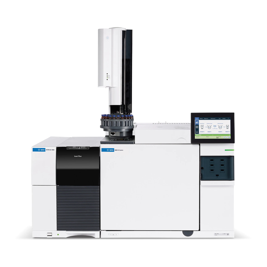
Introduction 1 MSD Hardware Description 7890B GC control panel 7890B GC 5977B Series MSD power switch System status LED GC power switch Figure 1 5977B Series GC/MSD system, shown with an Agilent 7890B GC 5977B Series MSD Operating Manual... - Page 20 Chapter 5, “Operating in CI Mode” on page 119.) The 5977B Series CI system field upgrade adds the following to the 5977B Series MSD: • EI/CI GC/MSD interface • JetClean option that shares the same MFC system EI/CI GC/MSD interface •...
-
Page 21: Important Safety Warnings
The printed circuit boards in the MSD can be damaged by electrostatic discharge. Do not touch any of the boards unless it is absolutely necessary. If you must handle them, wear a grounded wrist strap, and take other antistatic precautions. 5977B Series MSD Operating Manual... - Page 22 The oil pan under the foreline pump can be a fire hazard Oily rags, paper towels, and similar absorbents in the oil pan could ignite and damage the pump and other parts of the MSD. 5977B Series MSD Operating Manual...
-
Page 23: Hydrogen Safety
• Hydrogen has a very low ignition energy. • Hydrogen that is allowed to expand rapidly from high pressure can self-ignite. • Hydrogen burns with a nonluminous flame which can be invisible under bright light. 5977B Series MSD Operating Manual... -
Page 24: Gc Precautions
All users should be aware of the mechanisms by which hydrogen can accumulate and know what precautions to take if they know or suspect that hydrogen has accumulated. (See Table 4 on page 25.) Note that these mechanisms apply to all mass spectrometers, including the MSD. 5977B Series MSD Operating Manual... - Page 25 After a power failure, the mass spectrometer may start up and begin the pumpdown WA R N I N G process by itself. This does not guarantee that all hydrogen has been removed from the system, or that the explosion hazard has been removed. 5977B Series MSD Operating Manual...
-
Page 26: Precautions
• Turn off the hydrogen at its source every time shutoff valves in an MSD are closed. (Do not heat the capillary column without carrier gas flow.) • Turn off the hydrogen at its source if a power failure occurs. 5977B Series MSD Operating Manual... - Page 27 Environmental Health and Safety (EHS) requirements. Always check for leaks after changing a tank or servicing the gas lines. Ensure the foreline pump exhaust and GC injection port vents are both vented into a fume hood. 5977B Series MSD Operating Manual...
-
Page 28: Safety And Regulatory Certifications
This ISM device complies with Canadian ICES-001. Cet appareil ISM est conforme a la norme NMB—001 du Canada. The 5977B Series MSD is designed and manufactured under a quality system registered to ISO 9001. The 5977B Series MSD is RoHS compliant. - Page 29 Failure to comply with these precautions violates safety standards of design and the intended use of the instrument. Agilent Technologies assumes no liability for the customer’s failure to comply with these requirements.
-
Page 30: Electromagnetic Compatibility
4 Ensure that all peripheral devices are also certified. 5 Ensure that appropriate cables are used to connect the device to peripheral equipment. 6 Consult your equipment dealer, Agilent Technologies, or an experienced technician for assistance. Changes or modifications not expressly approved by Agilent Technologies could void the user’s authority to operate the equipment. -
Page 31: Intended Use
If you plan to move or store your MSD, additional precautions are required: • The MSD must remain upright at all times; this requires special caution when moving. • The MSD should not be left vented to atmosphere for long periods. 5977B Series MSD Operating Manual... -
Page 32: To Replace The Primary Fuses
2 Turn one of the fuse holders counterclockwise until it pops out. The fuse holders are spring loaded. (See Figure 2 on page 33.) 3 Remove the old fuse from the fuse holder. 4 Install a new fuse in the fuse holder. 5 Reinstall the fuse holder. 5977B Series MSD Operating Manual... - Page 33 1 Primary fuses in holders Figure 2 Primary fuses 6 Repeat steps through for the other fuse. Always replace both fuses. 7 Reconnect the MSD power cord to the electrical outlet. 8 Pumpdown the MSD. 5977B Series MSD Operating Manual...
- Page 34 Introduction 5977B Series MSD Operating Manual...
- Page 35 Agilent 5977B Series MSD Operating Manual Installing 7890 GC Columns Columns To Install a Capillary Column in a Split/Splitless Inlet To Condition a Capillary Column To Install a Capillary Column in the GC/MS Interface Using the Self-Tightening Column Nut To Install a Capillary Column in the GC/MS Interface Using a Standard...
-
Page 36: Installing 7890 Gc Columns
* Total gas flow into the MSD: column flow plus reagent gas flow (if applicable) plus JetClean H flow (if applicable). Based on helium gas use. For other gases the maximum flow will vary. † Expect degradation of spectral performance and sensitivity. 5977B Series MSD Operating Manual... - Page 37 Tips and hints • The column installation procedures for the 5977B Series MSDs may be different from that for previous MSDs. Using the procedure from another instrument may not work, and may damage the column or the MSD.
-
Page 38: To Install A Capillary Column In A Split/Splitless Inlet
WA R N I N G your skin with the end of the column. Always wear clean gloves while handling any parts that go inside the GC or analyzer C A U T I O N chambers. 5977B Series MSD Operating Manual... - Page 39 5 Inspect the end for jagged edges or burrs. If the break is not clean and even, repeat steps 3 and 4. 6 Wipe the outside of the free end of the column with a lint-free cloth moistened with methanol. 5977B Series MSD Operating Manual...
- Page 40 14 Verify flow by submerging the free end of the column in isopropanol. Look for bubbles. See also For more information about installing a capillary column, refer to Optimizing Splitless Injections on Your GC for High Performance MS Analysis, Agilent Technologies publication number 5988-9944EN. 5977B Series MSD Operating Manual...
-
Page 41: To Condition A Capillary Column
6 Set the GC oven temperature to 30 °C, and wait for the GC to become ready. 7 Attach the column to the GC interface. (See “To Install a Capillary Column in the GC/MS Interface Using the Self-Tightening Column Nut” on page 42.) 5977B Series MSD Operating Manual... -
Page 42: To Install A Capillary Column In The Gc/Ms Interface Using The Self-Tightening Column Nut
0.40 mm id, for 0.25 mm id columns (5181-3323) • 0.5 mm id, for 0.32 mm id columns (5062-3514) • 0.8 mm id, for 0.53 mm id columns (5062-3512) • Septum (may be old, used inlet septum) • Safety glasses 5977B Series MSD Operating Manual... - Page 43 8 Inspect the end for jagged edges or burrs. If the break is not clean and even, repeat steps 6 and 7. 9 Wipe the end with alcohol. 5977B Series MSD Operating Manual...
- Page 44 Figure 5 Installing a capillary column in the GC/MS interface for an EI EXT, SS, Inert, or CI source. Figure 6 Installing a capillary column in the GC/MS interface for an EI HES source. 5977B Series MSD Operating Manual...
- Page 45 50.) Do not use a tip seal or spring with an EI SS or Inert source. The interface socket on these sources does not allow the tip seal installation to fit. (See Figure 56 on page 175.) 5977B Series MSD Operating Manual...
- Page 46 16 You can align the ion source and interface tip seal by wiggling the side plate on its hinge. If the door still will not close, contact your Agilent Technologies service representative. 17 Close the analyzer chamber door. (See “To Close the Analyzer Chamber” page 196.) 5977B Series MSD Operating Manual...
-
Page 47: To Install A Capillary Column In The Gc/Ms Interface Using A Standard Column Nut
0.5 mm id, for 0.32 mm id columns (5062-3506) • 0.8 mm id, for 0.53 mm id columns (5062-3512) • Septum (may be old, used inlet septum) • Safety glasses • Wrench, open-end, 1/4-inch and 5/16-inch (8710-0510) 5977B Series MSD Operating Manual... - Page 48 10 Adjust the column so it extends this specified distance from the end of the transfer line. For an XTR, SS, Inert, or CI Source Installation (See Figure 5 page 44.), the column extends about 1 mm. 5977B Series MSD Operating Manual...
- Page 49 17 You can align the ion source and interface tip seal by wiggling the side plate on its hinge. If the door still will not close, contact your Agilent Technologies service representative. 18 Close the analyzer chamber door. (See “To Close the Analyzer Chamber” page 196.) 5977B Series MSD Operating Manual...
-
Page 50: To Install The Interface Tip Seal
2 Place the tip seal spring over the end of the interface. 3 Remove the interface tip seal from the ion source storage box, and place it over the end of the interface. Interface tip seal Figure 8 Interface tip seal 5977B Series MSD Operating Manual... - Page 51 5 You can align the analyzer and interface by wiggling the side plate on its hinge. If the analyzer still will not close, contact your Agilent Technologies service representative.
-
Page 52: To Calibrate Column Flow Linear Velocity
5 In the Instrument Control view, select GC Parameters from the Instrument menu. 6 Select the Configuration tab and then select the Columns tab. 7 Select your installed column from the table. 8 Click Calibrate to display the Calibrate Column dialog. 5977B Series MSD Operating Manual... - Page 53 12 Click OK to save the changes and exit the dialog. 13 Click OK on the Calibrate Columns dialog to save the calibration. With capillary columns, such as those used with the MSD, linear velocity is often measured rather than volumetric flow rate. 5977B Series MSD Operating Manual...
- Page 54 = Retention time in seconds Calculation for volumetric flow rate 0.785 D --------------------------- - Volumetric flow rate (mL/min) = where: D = Internal column diameter in millimeters L = Column length in meters t = Retention time in minutes 5977B Series MSD Operating Manual...
-
Page 55: The Gc/Msd Interface For A 7890B Series Gc
Ionization chamber Ion source Analyzer GC oven chamber Optional entry for CI reagent gas or JetClean system hydrogen Heater/Sensor assembly Figure 10 GC/MSD interface for a 7890B GC with EI XTR, HES, and CI sources 5977B Series MSD Operating Manual... - Page 56 GC/MS Interface Using a Standard Column Nut” on page 47.) The GC/MSD interface operates at high temperatures. If you touch it when it is hot, WA R N I N G it will burn you. 5977B Series MSD Operating Manual...
- Page 57 Agilent 5977B Series MSD Operating Manual Intuvo 9000 GC Column Maintenance Columns To Replace an Intuvo GC Column To Replace an Intuvo 9000 GC Gasket To Install a Column Guard or Jumper Chip To Replace the 9000 GC/MS Tail To Install the Interface Tip Seal...
-
Page 58: Intuvo 9000 Gc Column Maintenance
Maximum recommended gas flow, mL/min 4 to 6 † Maximum gas flow, mL/min Maximum column id 0.53 mm (30 m length) Total gas flow into the MS = column flow † Expect degradation of spectral performance and sensitivity 5977B Series MSD Operating Manual... -
Page 59: Conditioning Columns
MS power. If the foreline pump is off, hydrogen will accumulate in the MS and an explosion may occur. Read “Hydrogen Safety” on page 23 before operating the MS with hydrogen gas. 5977B Series MSD Operating Manual... - Page 60 • Avoid scratching or deforming click and run sealing surfaces. • If you need to clean a sealing surface, use clean, compressed air. • Use a new gasket each time you install a column or Intuvo chip. 5977B Series MSD Operating Manual...
-
Page 61: To Replace An Intuvo Gc Column
“To Vent the MSD” on page 113.) If you are using hydrogen or other flammable gas as a carrier gas, close the manual gas supply valve to the instrument before turning off the MS power. 5977B Series MSD Operating Manual... - Page 62 Open the bus door and remove it by lifting the door vertically off its hinge pins. Lower the oven door. Using the Intuvo torque driver, rotate all four column clamps off the column's retainer ring. 5977B Series MSD Operating Manual...
- Page 63 Using the Intuvo torque driver, remove the two compression bolts that seal the column's click and run connectors to the bus and store for later use. 10 Remove and store the column for later use in accordance with the column manufacturer's recommendations. 5977B Series MSD Operating Manual...
- Page 64 Over-tightening can damage the flow path, strip the fittings, and cause leaks. 18 Tighten the compression bolts until you hear a click from the Intuvo torque driver. 19 Close the column door. 20 Install the bus door. 21 Close the GC front door. 5977B Series MSD Operating Manual...
-
Page 65: To Replace An Intuvo 9000 Gc Gasket
Place the hole in the gasket over the alignment stud in the bus fitting, and press the gasket body flat against the bus. Check that the gasket's round lobes fit flat against the bus click and run fitting. The new gasket is ready for the chip or column attachment. 5977B Series MSD Operating Manual... -
Page 66: To Install A Column Guard Or Jumper Chip
Inlets > Guard Chip > Prepare for Maintenance >Replace Liner and Guard Chip > Start Maintenance. This procedure cools the inlet, detector, column, Guard Chip, and other components in the flow path heated zones to < 40 °C and configures the GC. Follow the on-screen GC prompts. 5977B Series MSD Operating Manual... - Page 67 Open the bus door and remove it by lifting the door vertically off its hinge pins. Pull the compression bolt access plate out to allow the torque driver to access the Guard chip compression bolt. 5977B Series MSD Operating Manual...
- Page 68 16 Finger tighten the compression bolt. 17 Raise the Guard Chip heater. 18 Finger tighten the Guard Chip screw in the inlet base. 19 Tighten the Guard Chip screw in the inlet base with a 7/16-inch open end wrench. 5977B Series MSD Operating Manual...
- Page 69 20 Tighten the Guard Chip compression bolt using the provided torque driver until you hear one click. 21 Install the inlet cover. 22 Install the bus door on its hinges and close it. 23 Close the GC front door. 24 If removed, install the ALS injector. 5977B Series MSD Operating Manual...
-
Page 70: To Replace The 9000 Gc/Ms Tail
9000 GC/MS Tail, and other components in the flow path heated zones to < 40 °C. If you are using hydrogen or other flammable gas as a carrier gas, close the manual gas supply valve to the instrument before turning off the MS power. 5977B Series MSD Operating Manual... - Page 71 MS tail heater assembly clamp Compression bolts Figure 15 MS tail heater assembly clamp closed 10 Open the MS tail heater assembly by loosening the thumb screw at the top of the clamp and rotating the clamp down. 5977B Series MSD Operating Manual...
- Page 72 14 Carefully slide the 9000 GC/MS Tail into the GC/MS interface, and gently place the click and run connection into the bus connection. 15 Check that the 9000 GC/MS Tail click and run fitting sits flat against the gasket in the bus connection. 5977B Series MSD Operating Manual...
- Page 73 26 You can align the ion source and interface tip seal by wiggling the side plate on its hinge. If the door still will not close, contact your Agilent Technologies service representative. 27 Close the analyzer chamber. (See “To Close the Analyzer Chamber” page 196.) 5977B Series MSD Operating Manual...
-
Page 74: To Condition An Intuvo Capillary Column
Use MassHunter to run an air and water check. Proceed to the next step if the air and water are within limits. Program the column temperature to increase from 120 °C to the maximum temperature limit for the column at a rate of 10 to 15 °C/min. 5977B Series MSD Operating Manual... - Page 75 Never exceed the maximum column temperature, in the GC/MS interface, the GC oven, C A U T I O N or the inlet. Hold at the maximum temperature for 30 minutes. The column is conditioned and ready to be used with your method. 5977B Series MSD Operating Manual...
-
Page 76: To Install The Interface Tip Seal
In this order, slide the spring, tip seal, and knurled tip seal retainer over the column sleeve. Thread the knurled tip seal retainer into the tip seal hold finger tight. Interface tip seal Knurled tip seal retainer Tip seal holder Figure 18 Interface tip seal 5977B Series MSD Operating Manual... -
Page 77: The Gc/Ms Interface For A 9000 Series Gc
5 You can align the analyzer and interface by wiggling the side plate on its hinge. If the analyzer still will not close, contact your Agilent Technologies service representative. - Page 78 The 9000 GC/MS Tail should be operated in the 250 to 350 C range. Subject to that restriction, the transfer line temperature should be slightly higher than the column temperature, but never higher than the maximum column temperature. 5977B Series MSD Operating Manual...
- Page 79 To Pumpdown the MSD This chapter describes how to perform some basic operating procedures for the Agilent 5977B Series GC/MSD using EI. If you are using the Agilent Intuvo 9000 Gas Chromatograph with your MS, Chemical Ionization (CI) and the JetClean system are not currently supported.
-
Page 80: Operating In Ei Mode
The software and firmware are revised periodically. If the steps in these procedures do C A U T I O N not match your , refer to the Agilent MassHunter GC/MS Acquisition software manuals and online help supplied with the software for more information. 5977B Series MSD Operating Manual... -
Page 81: Operating The Msd From The Gc Control Panel
Figure 20.) For 7890A+ models with updated firmware, this key is labeled Aux Det # which can be substituted for the key in the procedures that follow. MS/Aux Det Figure 20 7890B GC control panel 5977B Series MSD Operating Manual... - Page 82 To pumpdown the MSD from the GC control panel 1 Press MS/Aux Det to display the 5977B MSD menu. 2 Press the down arrow to scroll to Start MSD Pumpdown?. 3 Press On/Yes to start the pumpdown cycle. 5977B Series MSD Operating Manual...
- Page 83 2 Press the down arrow to scroll to Request MSD Reboot?. 3 Press On/Yes to reboot the MSD and wait for the MSD to complete this cycle before trying to access it. The LED turns red until the reboot cycle is completed. 5977B Series MSD Operating Manual...
- Page 84 To disable BOOTP, press Off/No. 4 Wait for the MSD to confirm the change on the GC control panel. 5 Reboot the MSD. (See “To reboot the MSD from the GC control panel” page 83.) 5977B Series MSD Operating Manual...
-
Page 85: Configuring The Msd Through The Web User Interface (Wui)
3 Copy the IP address, gateway, and subnet mask from the mini display readout. The defaults for each are 192.168.254.12, 0.0.0.0, and 255.255.255.0 respectively. 4 Enter the IP address into a PC web browser URL to display the WUI page. (See Figure 21 on page 86.) 5977B Series MSD Operating Manual... - Page 86 Operating in EI Mode Figure 21 WUI main menu 5 Click Set Real-Time Clock or Edit NetConfig, and go to Edit NetConfig (MSD network configuration). (See Figure 22.) Figure 22 WUI Edit NetConfig 5977B Series MSD Operating Manual...
- Page 87 9 Click OK to close the dialog and wait for the prompt requesting to Manually reboot of the MSD/SmartCard to activate the new Settings. 10 Use the MSD on/off switch to reboot the MSD SmartCard. 5977B Series MSD Operating Manual...
-
Page 88: Emodule Mini Display Readout
Solid yellow JetClean Acquire & Clean operation Blinking magenta JetClean Clean Only operation Solid magenta Ready and not connected to DS Solid blue Start up (prior to FW load) Blinking red (<2 sec) Fault Solid red 5977B Series MSD Operating Manual... -
Page 89: Before You Turn On The Msd
JetClean system supply shutoff valves must be closed before turning off the MS power. If the foreline pump is off, hydrogen will accumulate in the MS and an explosion may occur. Read “Hydrogen Safety” on page 23 before operating the MSD with hydrogen gas. 5977B Series MSD Operating Manual... -
Page 90: Pumping Down
Constant Pressure to maintain a constant inlet pressure, and the column flow will decrease as the GC oven temperature increases. With EPC and the column mode set to Constant Flow, the same column flow is maintained regardless of temperature. 5977B Series MSD Operating Manual... -
Page 91: Controlling Jetclean Hydrogen Flow
JetClean system supply shutoff valves must be closed before turning off the MS power. If the foreline pump is off, hydrogen will accumulate in the MS and an explosion may occur. Read “Hydrogen Safety” on page 23 before operating the MSD with hydrogen gas. 5977B Series MSD Operating Manual... - Page 92 Do not vent while the turbo pump is still spinning at more than 50%. Do not exceed the maximum recommended total gas flow. (See Table 3 on page 18.) 5977B Series MSD Operating Manual...
-
Page 93: To View Msd Temperature And Vacuum In Manual Tune
1 In Instrument Control view, select Edit Tune Parameters from the Instrument menu to display the Manual Tune dialog. 2 Click the Values tab to view the MSD Temperatures and Vacuum. (See Figure 24 Figure 25 on page 94.) Figure 24 Manual tune values tab 5977B Series MSD Operating Manual... - Page 94 The MSD heaters turn on at the end of the pumpdown cycle, and turn off at the beginning of the vent cycle. The reported setpoints will not change during venting or pumpdown, even though both MSD zones are turned off. 5977B Series MSD Operating Manual...
-
Page 95: To Set Monitors For Msd Temperature And Vacuum Status
2 In the Available Monitors column, select a monitor, and click Add to move the selection to the Selected Monitors column. Repeat for additional monitors. 3 Click OK. The new monitors will be stacked on top of each other in the lower right corner of the Instrument Control window. 5977B Series MSD Operating Manual... - Page 96 Operating in EI Mode 4 Select Window > Arrange Monitors, or click and drag each monitor to the desired position. (See Figure 27.) Figure 27 Arranging monitors 5977B Series MSD Operating Manual...
- Page 97 Enter descriptive text in the Monitor Label field if the default label is not appropriate. d Click OK to finish the monitor’s alarm configuration. 6 To make the new settings part of the method, save the Method. 5977B Series MSD Operating Manual...
-
Page 98: To Set Analyzer Temperatures From The Instrument Control View
The GC/MSD interface, ion source, and quadrupole heated zones interact. The analyzer heaters may not be able to accurately control temperatures if the setpoint for one zone is much different from that of an adjacent zone. 5977B Series MSD Operating Manual... - Page 99 Save MS Tune File dialog displays. Click OK to save your changes to the same file, or type a new file name and click OK. Click Cancel to discard the edit made to any parameter. 5977B Series MSD Operating Manual...
-
Page 100: To Set The Masshunter 7890 Gc/Msd Interface Temperature
When setting the GC/MS interface temperature, never exceed the maximum for your column. 4 Click Apply to download setpoints, or click OK to download setpoints and close the window. 5 To make the new settings part of the method, select Save from the Method menu. 5977B Series MSD Operating Manual... -
Page 101: To Monitor High Vacuum Pressure
3 In the Tune and Vacuum Control view, select Turn Vacuum Gauge on/off from the Vacuum menu. 4 Select Manual Tune from the Parameters menu to display the Manual Tune dialog. 5 Select the Values tab to view the HiVac reading. (See Figure 31 on page 102.) 5977B Series MSD Operating Manual... - Page 102 Torr Gauge reading, Torr Foreline reading, mTorr mL/min Turbo pump Diffusion pump Diffusion pump 3.18E–06 2.18E–05 34.7 4.42E–06 2.59E–05 39.4 6.26E–06 3.66E–05 52.86 7.33E–06 4.46E–05 60.866 1.24E–05 7.33E–05 91.784 1.86E–05 1.13E–04 125.76 2.48E–05 3.75E–05 5977B Series MSD Operating Manual...
- Page 103 In the Instrument Control view, you can set up an MSD Monitor for displaying this vacuum reading. The vacuum can also be read on the 7890A+ or 7890B GC series control panel or from the Manual Tune screen. 5977B Series MSD Operating Manual...
-
Page 104: To Tune The Msd In Ei Mode
4 Click the MS Tune icon to display the Select Tune Type dialog. (See Figure 32.) Figure 32 Select tune type dialog 5 Select Tune MSD to perform a complete autotune, or select Quick Tune to adjust peak width, mass assignment, and abundance, without changing ion ratios. 5977B Series MSD Operating Manual... - Page 105 To manually tune your MSD or to perform special autotunes, from the View menu select Tune and Vacuum Control view. See the manuals and online help provided with your Agilent MassHunter GC/MS Acquisition software for additional information about tuning. 5977B Series MSD Operating Manual...
-
Page 106: To Set The Operation Mode For The Optional Jetclean System
2 In the Single Quadrupole MS Method Editor navigation panel, select the JetClean tab. (See Figure 33.) 3 From the Operation dropdown menu, select a mode. Figure 33 Selecting the JetClean Operation mode For detailed information on the JetClean system see the JetClean Operating manual. 5977B Series MSD Operating Manual... -
Page 107: To Set The Jetclean Parameters For The Clean Only Mode
2 In the Single Quadrupole MS Method Editor, select the JetClean tab. (See Figure 34.) 3 From the Operation dropdown menu, select Clean Only. Figure 34 JetClean set to Clean Only mode 4 Enter the parameters supplied by your method developer. 5 Save the method. 5977B Series MSD Operating Manual... -
Page 108: To Verify Ei System Performance
4 Click OK to run the method. When the method is completed, an evaluation report will be printed. Verify that rms signal-to-noise ratio meets the published specification. See the Agilent Web site at www.agilent.com/chem for specifications. 5977B Series MSD Operating Manual... -
Page 109: To Perform High-Mass Testing
5 In Instrument Control view select High Mass Check from the Checkout menu. 6 Follow the instructions on screen. 7 The Run is completed, and results are printed within 5 minutes. (See Figure 35 on page 110.) 5977B Series MSD Operating Manual... - Page 110 Operating in EI Mode Figure 35 PFHT high mass report 5977B Series MSD Operating Manual...
- Page 111 7 Click Done to close the Manual Tune dialog. 8 Load the PFHT.M, then load the saved tune file, and then save the method. 9 Rerun test mixture (repeat high-mass checkout). If the correction is within 5 units, no further adjustments are required. 5977B Series MSD Operating Manual...
-
Page 112: To Open The Msd Covers
The cover is held in place by its hinges. (See Figure 36.) Do not remove any other covers. Dangerous voltages are present under other covers. WA R N I N G 5977B Series MSD Operating Manual... -
Page 113: To Vent The Msd
C A U T I O N flow to prevent damage to the column. 2 In the Instrument Control view, Instrument menu, select MS Vacuum Control to display the Vacuum Control dialog. (See Figure 37 on page 114.) 5977B Series MSD Operating Manual... - Page 114 6 Unplug the MS power cord. When the MS is vented, do not put the Agilent MassHunter GC/MS Acquisition WA R N I N G software into Instrument Control view. Doing so will turn on the interface heater. 5977B Series MSD Operating Manual...
- Page 115 (See Figure 38.) Vent valve knob Figure 38 Vent valve knob Do not turn the knob too far, or the O-ring may fall out of its groove. 5977B Series MSD Operating Manual...
-
Page 116: To Pumpdown The Msd
3 Verify that the vent valve is open by turning it clockwise until closed. (See Figure 39 on page 117.) 4 Open the vent valve by turning it counterclockwise 45 degrees. (See Figure 39 on page 117.) 5977B Series MSD Operating Manual... - Page 117 9 Start the Agilent MassHunter GC/MS Acquisition software. 10 In the Instrument Control view, from the Instrument menu, select MS Vacuum Control to display the Vacuum Control dialog. (See Figure 40 on page 118.) 5977B Series MSD Operating Manual...
- Page 118 Data acquired before the MSD has reached thermal equilibrium may not be reproducible. 14 If using the JetClean system, prepare the hydrogen system for use. Refer to the JetClean system Operating manual for warnings regarding hydrogen safety. 5977B Series MSD Operating Manual...
- Page 119 To Monitor CI Mode High Vacuum Pressure This chapter provides information and instructions for operating the 5977B Series CI MSDs in CI mode. Most of the information in the preceding chapter is also relevant. Most of the material is related to methane CI but one section discusses the use of other reagent gases.
-
Page 120: Operating In Ci Mode
• Ensure the reagent gas plumbing has no air leaks. This is determined in PCI mode, checking for m/z 32 after the methane pretune. • Ensure the reagent gas inlet line is equipped with gas purifiers (not applicable for ammonia). 5977B Series MSD Operating Manual... -
Page 121: Ci Autotune
Always verify MSD performance in EI before switching to CI operation. (See “To Verify C A U T I O N EI System Performance” on page 108.) Always set up the CI MSD in PCI first, even if you are going to run NCI. 5977B Series MSD Operating Manual... - Page 122 150 °C 150 °C 150 °C 150 °C 150 °C 150 °C 150 °C Interface temp 280 °C 280 °C 280 °C 280 °C 280 °C 280 °C 280 °C Autotune * N/A Not Available 5977B Series MSD Operating Manual...
-
Page 123: To Operate The Ci Msd
Depending upon the application, use the following reagent gas flow rates during system startup: • PCI mode set reagent gas flow to 20 (1 mL/min) • NCI mode set reagent gas flow to 40 (2 mL/min) 5977B Series MSD Operating Manual... -
Page 124: To Pumpdown The Msd In Ci Mode
123.) 6 Set Gas A (methane) to 20%. 7 Let the system bake out and purge for at least 2 hours. If you will be running NCI, for best sensitivity, bake out the MSD overnight. 5977B Series MSD Operating Manual... -
Page 125: To Set Up The Software For Ci Operation
µA Max electron energy, eV Notes for Table • N/A: Not available. There are no PFDTD ions formed in PCI with any reagent gas but methane, hence, CI autotune is not available with these configurations. 5977B Series MSD Operating Manual... - Page 126 • Peakwidth target: Higher peakwidth values give better sensitivity, lower values give better resolution. • Maximum emission: current Optimum emission current maximum for NCI is very compound-specific and must be selected empirically. Optimum emission current for pesticides, for example, may be about 200 µA. 5977B Series MSD Operating Manual...
-
Page 127: To Operate The Reagent Gas Flow Control Module
Procedure 1 In the Manual Tune dialog, click the CI Gas tab to access the parameter settings for controlling the CI gas flow. (See Figure 41.) Figure 41 Manual tune CI tab 5977B Series MSD Operating Manual... - Page 128 In this case, the Gas B supply is dedicated to hydrogen used for source cleaning. For detailed information on the JetClean system refer to the JetClean Operating manual installed on your PC along with this manual. 5977B Series MSD Operating Manual...
- Page 129 Closed setpoint setpoint 100% 100% 100% Shutoff valve Open Open Open Open Open Closed The Open and Closed states are shown in the monitors as Open and Closed respectively. 5977B Series MSD Operating Manual...
-
Page 130: To Set Up Methane Reagent Gas Flow
7 Select Methane Pretune from the Setup menu and follow the system prompts. See the Agilent MassHunter GC/MS Acquisition software online help for additional information. The methane pretune tunes the instrument for optimum monitoring of the ratio of methane reagent ions m/z 28/27. 5977B Series MSD Operating Manual... - Page 131 Note the low abundance of m/z 19 and absence of any visible peak at m/z 32. Your MSD will probably show more water at first, but the abundance of m/z 19 should still be less than 50% of m/z 17. 5977B Series MSD Operating Manual...
-
Page 132: To Use Other Reagent Gases
To Use Other Reagent Gases This section describes the use of isobutane or ammonia as the reagent gas. You should be familiar with operating the CI-equipped 5977B Series MSD with methane reagent gas before attempting to use other reagent gases. - Page 133 20%. If you use an existing tune file, be sure to save it with a new name if you do not want to overwrite the existing values. Accept the default temperature and other settings. 5977B Series MSD Operating Manual...
- Page 134 Ammonia tends to break down vacuum pump fluids and seals. Ammonia CI makes more frequent vacuum system maintenance necessary. Refer to the Agilent 5977B Series MSD Troubleshooting and Maintenance Manual. Frequently, a mixture of 5% ammonia and 95% helium or 5% ammonia and 95% methane is used as a CI reagent gas.
-
Page 135: To Perform A Pci Autotune (Methane Only)
The autotune report contains information about air and water in the system. (See “PCI autotune report” on page 136.) The 19/29 ratio shows the abundance of water. The 32/29 ratio shows the abundance of oxygen. 5977B Series MSD Operating Manual... - Page 136 Operating in CI Mode Figure 44 PCI autotune report 5977B Series MSD Operating Manual...
-
Page 137: To Perform An Nci Autotune (Methane Reagent Gas)
Figure 45 on page 138.) If the tune sets the EMV at or above 2,600 V, however, you may not be able to acquire data successfully if your method sets EMV to “+400” or higher. 5977B Series MSD Operating Manual... - Page 138 Operating in CI Mode Figure 45 NCI autotune 5977B Series MSD Operating Manual...
-
Page 139: To Verify Pci Performance
6 Run the PCI sensitivity method BENZ_PCI.M using 1 µL of 100 pg/µL benzophenone. 7 Verify that the system conforms to the published sensitivity specification. Please refer to the Agilent Web site at www.agilent.com/chem specifications. 5977B Series MSD Operating Manual... -
Page 140: To Verify Nci Performance
5 Run the NCI sensitivity method: OFN_NCI.M using 2 µL of 100 fg/µL OFN. 6 Verify that the system conforms to the published sensitivity specification. Please refer to the Agilent Web site at www.agilent.com/chem specifications. 5977B Series MSD Operating Manual... -
Page 141: To Monitor Ci Mode High Vacuum Pressure
142.) They were taken with the following set of conditions. Note that these are typical PCI temperatures: Source temperature 250 °C Quad temperature 150 °C Interface temperature 280 °C Helium carrier gas flow 1 mL/min 5977B Series MSD Operating Manual... - Page 142 Familiarize yourself with the measurements on your system under operating conditions and watch for changes that may indicate a vacuum or gas flow problem. Measurements will vary by as much as 30% from one MSD and gauge controller to the next. 5977B Series MSD Operating Manual...
- Page 143 Agilent 5977B Series MSD Operating Manual General Maintenance Before Starting Maintaining the Vacuum System Maintaining the Analyzer To Open the Analyzer Chamber To Remove the EI HES To Connect/Disconnect Wiring to the EI HES To Disassemble the EI HES To Clean the EI HES...
-
Page 144: General Maintenance
* Every 3 months for CI MSDs using ammonia reagent gas. † Vacuum seals other than the side plate O-ring and vent valve O-ring do not need to be lubricated. Lubricating other seals can interfere with their correct function. 5977B Series MSD Operating Manual... - Page 145 Perform no maintenance with the MSD turned on or plugged into its power source WA R N I N G unless you are instructed to by one of the procedures in this chapter. 5977B Series MSD Operating Manual...
- Page 146 The GC inlets and GC oven also operate at very high temperatures. Use the same caution around these parts. See the documentation supplied with your GC for more information. 5977B Series MSD Operating Manual...
- Page 147 The main effect of operating the MS in CI mode is the need for more frequent ion source cleaning. In CI operation, the ion source chamber is subject to more rapid contamination than in EI operation because of the higher source pressures required for CI. 5977B Series MSD Operating Manual...
-
Page 148: Electrostatic Discharge
Antistatic precautions are not 100% effective. Handle electronic circuit boards as little as possible and then only by the edges. Never touch components, exposed traces, or pins on connectors and cables. 5977B Series MSD Operating Manual... -
Page 149: Maintaining The Vacuum System
Other procedures Tasks such as replacing a foreline vacuum gauge or Micro-Ion vacuum gauge should be performed only when needed. Refer to the Agilent 5977B Series MSD Troubleshooting and Maintenance manual and the online help in Agilent MassHunter GC/MS Acquisition software for symptoms that indicate this type of maintenance is required. -
Page 150: Maintaining The Analyzer
• Cleaning the ion source • Replacing filaments • Replacing the electron multiplier horn The Agilent 5977B Series MSD Troubleshooting and Maintenance Manual provides information about symptoms that indicate the need for analyzer maintenance. The troubleshooting material in the online help in the Agilent MassHunter GC/MS Acquisition software provides more extensive information. - Page 151 Do not touch the HED ceramic insulator. More information is available If you need more information about the locations or functions of analyzer components, refer to the Agilent 5977B Series MSD Troubleshooting and Maintenance Manual. Many procedures in this chapter are illustrated with video clips.
-
Page 152: To Open The Analyzer Chamber
Do not touch any part until you are sure it is cool. Always wear clean gloves to prevent contamination when working in the analyzer C A U T I O N chamber. 5977B Series MSD Operating Manual... - Page 153 Verify that the MS is vented. Verify that both the front and rear side plate screws are completely loose. 4 Gently swing the side plate out. Side plate Ceramic source board Ion source Analyzer Figure 46 The analyzer chamber for an Inert+ model MSD 5977B Series MSD Operating Manual...
-
Page 154: To Remove The Ei Hes
155.) 4 Disconnect the wires from the EI HES. (See Figure 47 on page 155.) Do not bend the wires any more than necessary. (See “To Connect/Disconnect Wiring to the EI HES” on page 156.) 5977B Series MSD Operating Manual... - Page 155 The source contacts have spring loaded pins so some force must be applied to pull the source out. Ion source Thumbscrew Ceramic source board Source finger grip Thumbscrew Source heater and temperature sensor wires Source radiator Figure 47 The analyzer chamber for the HES MSD 5977B Series MSD Operating Manual...
-
Page 156: To Connect/Disconnect Wiring To The Ei Hes
(red, white, black, and gray) at the source connectors. (See Figure 48.) Ceramic source board Repeller Filament common Filament 1 Filament 2 Figure 48 Wiring between the ceramic source board and the EI HES 5977B Series MSD Operating Manual... -
Page 157: To Disassemble The Ei Hes
Use care when removing the lenses from the lens insulator casing. Putting excessive C A U T I O N stress on this casing can break or crack it. If this happens, do not attempt to operate with a defective lens insulator, it must be replaced. 5977B Series MSD Operating Manual... - Page 158 Exploded parts view of the EI HES Table 17 Parts list for EI HES (Figure Item number Item description Part number Source finger grip G7002-20008 Filament block G7002-20019 Extractor lens (5)*, with 3 mm opening G7002-20061 Ceramic insulator for extractor G7002-20064 5977B Series MSD Operating Manual...
- Page 159 G7002-20126 High efficiency dual filament G7002-60001 Ring heater/sensor assembly G7002-60043 Source mount 1.5 mm G7002-60053 Repeller assembly G7002-60057 Not shown HES assembly G7004-67055 * The number in parenthesis is the number engraved on the lens 5977B Series MSD Operating Manual...
-
Page 160: To Clean The Ei Hes
Source mount (does not get abrasively or ultrasonically cleaned) • Repeller • Source body • Extractor lens (5) • Post extractor lens 1 (4) • Post extractor lens 2 (3) • Ion focus lens (2) • Entrance lens (1) 5977B Series MSD Operating Manual... - Page 161 3 If the contamination is serious, such as an oil backflow into the analyzer, seriously consider replacing the contaminated parts Do not use the abrasive slurry on the source mount bushings. C A U T I O N 5977B Series MSD Operating Manual...
- Page 162 WA R N I N G precautions. 8 Place the parts in a clean beaker. Loosely cover the beaker with clean aluminum foil (dull side down). 9 Dry the cleaned parts in an oven at 100 °C for 5–6 minutes. 5977B Series MSD Operating Manual...
-
Page 163: To Assemble The Ei Hes
1. Rotate each lens until you feel the ball seat into the circular recess. It is easier to insert lens 5 on an angle because the lens stack at this point makes the lens insulator less flexible. 5977B Series MSD Operating Manual... - Page 164 Verify that the ceramic is sitting flush at the end of the source body. 4 Using the T6 Torx driver, install and secure the gold plated setscrew and lock ring lens insulator that holds the lens assembly in place. 5977B Series MSD Operating Manual...
- Page 165 Fully insert the three filament leads into the filament block. 11 Inset the filament block into the source holder, and use a T6 Torx screwdriver to secure it to the holder with the gold plated screw. 5977B Series MSD Operating Manual...
- Page 166 Source finger grip G7002-20008 Filament block G7002-20019 Extractor lens (5)*, with 3 mm opening G7002-20061 Ceramic insulator for extractor G7002-20064 Entrance lens assembly, Extended, HES (1)* G7002-20165 Ion focus lens (2)* G7002-20068 Lens insulator/holder G7002-20074 5977B Series MSD Operating Manual...
- Page 167 Use care when inserting the lenses into the lens insulator casing. Putting excessive C A U T I O N stress on this casing can break or crack it. If this happens, do not attempt to operate with a defective lens insulator, it must be replaced. 5977B Series MSD Operating Manual...
-
Page 168: To Remove The Ei Hes Filaments
3 Remove the ion source and place it on a clean cloth on your work surface. (See “To Remove the EI HES” on page 154.) 4 Remove the screw securing the filament block to the source mount. (See Figure 54 on page 169.) 5977B Series MSD Operating Manual... - Page 169 6 Remove the dual filament from the filament block by lifting the source body up off of the filament block, while holding the filament block so that the dual filament will not fall and become damaged. 5977B Series MSD Operating Manual...
-
Page 170: To Install The Ei Hes Filament
“To Install the EI HES” on page 171.) 6 Close the analyzer chamber. (See “To Close the Analyzer Chamber” page 196.) 7 Pumpdown the MSD. (See “To Pumpdown the MSD” on page 116.) 8 Autotune the MSD. 5977B Series MSD Operating Manual... -
Page 171: To Install The Ei Hes
5 Close the analyzer chamber. (See “To Close the Analyzer Chamber” page 196.) 6 Pumpdown the MSD. (See “To Pumpdown the MSD” on page 116.) 7 Tune the MSD. (See “To Tune the MSD in EI Mode” on page 104.) 5977B Series MSD Operating Manual... -
Page 172: To Remove The Ei Xtr, Ss, Or Inert Source
“To Connect/Disconnect Wiring from the EI XTR, SS, and Inert Sources” on page 173.) 4 Remove the thumbscrews that hold the ion source in place. (See Figure 62 on page 193.) 5 Pull the ion source out of the source radiator. 5977B Series MSD Operating Manual... -
Page 173: To Connect/Disconnect Wiring From The Ei Xtr, Ss, And Inert Sources
2 Use tweezers or needle nose pliers to connect/disconnect the source heater wire leads at the ceramic source board. Ceramic source board Entrance lens Ion focus lens Filament 1 Repeller Filament 2 Extractor lens Source heater Source RTD Figure 55 Wiring for the EI XTR Source 5977B Series MSD Operating Manual... -
Page 174: To Disassemble The Ei Ss Or Ei Inert Source
8 Unscrew the interface socket. A 10-mm open-end wrench fits the flats on the interface socket. 9 Remove the entrance lens and ion focus lens from the lens insulator. 5977B Series MSD Operating Manual... - Page 175 Part number (SS) Part number (Inert) Gold plated set screw G1999-20022 G1999-20022 Gold plated screw G3870-20021 G3870-20021 Interface socket G1099-20136 G1099-20136 Source body G1099-20130 G2589-20043 Drawout cylinder G1072-20008 G1072-20008 Drawout plate 05971-20134 G2589-20100 4-turn filament G7005-60061 G7005-60061 5977B Series MSD Operating Manual...
- Page 176 Ion focus lens 05971-20143 05971-20143 Repeller insulator G1099-20133 G1099-20133 Repeller G3870-60172 G3870-60173 Flat washer 3050-0627 3050-0627 Belleville spring washer 3050-1301 3050-1301 Repeller nut 0535-0071 0535-0071 Source heater block assembly G3870-60180 G3870-60179 Repeller block insert G3870-20135 G3870-20135 5977B Series MSD Operating Manual...
-
Page 177: To Disassemble The Ei Xtr Source
7 Separate the entrance lens and ion focus lens from the lens insulator. 8 Remove the repeller nut, washers, and insulator from the front side of the source heater block assembly, then remove the repeller, insulator, and repeller block insert from the opposite side. 5977B Series MSD Operating Manual... - Page 178 Disassembling the EI XTR source Table 20 Parts list for EI XTR source (Figure Item Description Part number Setscrews G3870-20446 Screws G3870-20021 Source body G3870-20440 Extractor lens G3870-20444 Extractor lens insulator G3870-20445 Filaments G7005-60061 Spring washer 3050-1301 5977B Series MSD Operating Manual...
- Page 179 Ion focus lens 05971-20143 Repeller insulator G1099-20113 Repeller G3870-60171 Flat washer 3050-0891 Belleville spring washer 3050-1301 Repeller nut 0535-0071 Source heater block assembly G3870-60177 Repeller block insert G3870-20135 Not shown EI XTR source assembly G7003-67720 5977B Series MSD Operating Manual...
-
Page 180: To Clean An Ei Xtr, Ss, Or Inert Source
2 Collect the following parts to be cleaned for an EI SS or Inert source: (See Figure 58 on page 182.) • Repeller • Interface socket • Source body • Repeller block insert • Drawout plate • Drawout cylinder • Ion focus lens • Entrance lens 5977B Series MSD Operating Manual... - Page 181 If insulators are dirty, clean them with a cotton swab dampened with reagent-grade C A U T I O N methanol. If that does not clean the insulators, replace them. Do not abrasively or ultrasonically clean the insulators. 5977B Series MSD Operating Manual...
- Page 182 Source body socket plate block insert lens lens cylinder EI XTR source parts to be cleaned Repeller Repeller block Entrance Ion focus lens Extractor lens Source body insert lens Figure 58 Source parts to be cleaned 5977B Series MSD Operating Manual...
- Page 183 (dull side down). 7 Dry the cleaned parts in an oven at 100 °C for 5–6 minutes. Let the parts cool before you handle them. WA R N I N G 5977B Series MSD Operating Manual...
- Page 184 Take care to avoid recontaminating cleaned and dried parts. Put on new, clean gloves N O T E before handling the parts. Do not set the cleaned parts on a dirty surface. Set them only on clean, lint-free cloths. 5977B Series MSD Operating Manual...
-
Page 185: To Assemble An Ei Ss Or Inert Source
6 Install the interface socket. 7 Attach the repeller assembly to the source body using the two gold plated screws and spring washers. 8 Install the filaments using the two gold plated screws and spring washers. 5977B Series MSD Operating Manual... - Page 186 Parts list for the EI standard or EI Inert source (Figure Item number Item description Part number (SSL) Part number (Inert) Gold plated set screw G1999-20022 G1999-20022 Gold plated screw G3870-20021 G3870-20021 Interface socket G1099-20136 G1099-20136 Source body G1099-20130 G2589-20043 5977B Series MSD Operating Manual...
- Page 187 Ion focus lens 05971-20143 05971-20143 Repeller insulator G1099-20133 G1099-20133 Repeller G3870-60172 G3870-60173 Flat washer 3050-0627 3050-0627 Belleville spring washer 3050-1301 3050-1301 Repeller nut 0535-0071 0535-0071 Source heater block assembly G3870-60180 G3870-60179 Repeller block insert G3870-20135 G3870-20135 5977B Series MSD Operating Manual...
-
Page 188: To Assemble The Ei Xtr Source
Do not overtighten the repeller nut or the ceramic repeller insulators will break when C A U T I O N the source heats up. The nut should only be finger tight. 5977B Series MSD Operating Manual... - Page 189 8 Install the filaments using the two gold plated screws and spring washers. Figure 60 Assembling the EI XTR source Table 22 Parts list for EI XTR source (Figure Item Description Part number Setscrews G3870-20446 Screws G3870-20021 Source body G3870-20440 5977B Series MSD Operating Manual...
- Page 190 Ion focus lens 05971-20143 Repeller insulator G1099-20113 Repeller G3870-60171 Flat washer 3050-0891 Belleville spring washer 3050-1301 Repeller nut 0535-0071 Source heater block assembly G3870-60177 Repeller block insert G3870-20135 Not shown EI XTR source assembly G7003-67720 5977B Series MSD Operating Manual...
-
Page 191: To Replace A Filament In An Ei Xtr, Ss, Or Inert Source
152.) 3 Remove the ion source. (See “To Remove the EI XTR, SS, or Inert Source” page 172.) 4 Remove the gold plated screw and washer for the filaments. (See Figure 61 on page 192.) 5977B Series MSD Operating Manual... - Page 192 13 Enter the filament number that gave the best results. If you decide to use the first filament number, run Autotune again to make sure the tune parameters are compatible with the filament. 14 Select Save Tune Parameters from the File menu. 5977B Series MSD Operating Manual...
-
Page 193: To Install The Ei Xtr, Ss, Or Inert Source
62.) 3 Connect the ion source wires. (See “To Connect/Disconnect Wiring from the EI XTR, SS, and Inert Sources” on page 173.) 4 Close the analyzer chamber. (See “To Close the Analyzer Chamber” page 196.) 5977B Series MSD Operating Manual... -
Page 194: To Replace The Electron Multiplier Horn
4 Slide the blue signal wire from the connector in the sideplate. 5 Remove the electron multiplier horn. 6 Hold the new horn with blue signal wire end down, and attach the signal wire to the connector in the sideplate. 5977B Series MSD Operating Manual... - Page 195 9 Close the analyzer chamber. (See “To Close the Analyzer Chamber” page 196.) Electron multiplier horn Retaining clip Blue signal wire Figure 63 Replacing the EM horn on a Series II Detector Figure 64 Electron multiplier horn 5977B Series MSD Operating Manual...
-
Page 196: To Close The Analyzer Chamber
C A U T I O N pumpdown. Do not use a screwdriver to tighten the thumbscrew. 6 Once the MSD has pumped down, close the left analyzer cover and replace the window cover. 7 Tune the MSD. 5977B Series MSD Operating Manual... - Page 197 To Install the CI Source This chapter describes maintenance procedures and requirements that are unique to 5977B Series MSDs equipped with the CI hardware. If you are using the Agilent Intuvo 9000 Gas Chromatograph with your MS, Chemical Ionization (CI) and the JetClean system are not currently supported.
-
Page 198: Ci Maintenance
• Make sure the reagent gas inlet line(s) are equipped with gas purifiers (not applicable for ammonia). • Use extra-high purity reagent gases; 99.99% or better for methane and as pure as is available for other reagent gases. 5977B Series MSD Operating Manual... -
Page 199: To Switch From The Ei Hes To The Ci Source
11 Install the CI source. This requires shortening the column so that it protrudes from the transfer line by 1 to 2 mm. (See “To Install the CI Source” on page 225.) 12 Pumpdown the MSD. (See “To Pumpdown the MSD in CI Mode” page 124.) 5977B Series MSD Operating Manual... -
Page 200: To Remove The Ei Hes Radiator
Connect/Disconnect Wiring to the EI HES Radiator” on page 201.) Use a T10 Torx screwdriver to loosen the 2 screws that secure the radiator to the analyzer, and place the radiator in its storage container. 5977B Series MSD Operating Manual... -
Page 201: To Connect/Disconnect Wiring To The Ei Hes Radiator
Post extractor lens 1 (4)* Extractor lens (5)* Ground wire Heater wires RTD wires * The number in parenthesis is the number engraved on the lens. Figure 65 Wiring between the ceramic source board and the EI HES radiator 5977B Series MSD Operating Manual... -
Page 202: To Install The Ci Source Radiator
When disconnecting leads, pull on the connectors, not on the wires. C A U T I O N 1 Align the radiator over the two guide pins on the analyzer support, and secure it using the two retained screws with a number T10 Torx screwdriver. 5977B Series MSD Operating Manual... - Page 203 CI Maintenance 7 2 Connect the green ground wire to the radiator. (See Figure 66.) Radiator Green ground wire Figure 66 CI Source radiator 5977B Series MSD Operating Manual...
-
Page 204: To Switch From The Ci Source To The Ei Hes
GC/MS Interface Using the Self-Tightening Column Nut” on page 42 or “To Install a Capillary Column in the GC/MS Interface Using a Standard Column Nut” on page 47.) 11 Remove the EI HES radiator from the storage container. 5977B Series MSD Operating Manual... - Page 205 13 Remove the EI HES from the storage container. 14 Install the EI HES. (See “To Install the EI HES” on page 171.) 15 Pumpdown the MSD. (See “To Pumpdown the MSD” on page 116.) 5977B Series MSD Operating Manual...
-
Page 206: To Remove The Ci Source Radiator
Make sure you use an antistatic wrist strap and take other antistatic precautions C A U T I O N before touching analyzer components. When disconnecting leads, pull on the connectors, not on the wires. C A U T I O N 5977B Series MSD Operating Manual... - Page 207 3 Use a T-10 Torx screwdriver to loosen the two retained screws that secure the radiator to the analyzer and place the radiator in its storage container. Radiator Green ground wire Figure 67 CI Source radiator 5977B Series MSD Operating Manual...
-
Page 208: To Install The Ei Hes Radiator
T10 Torx screwdriver to secure it using the (2) M3 x 12 gold plated screws (part number G7002-20110). Use tweezers to disconnect the wires from the EI HES radiator. (See “To Connect/Disconnect Wiring to the EI HES Radiator” on page 201.) 5977B Series MSD Operating Manual... -
Page 209: To Switch From An Ei Xtr, Ss, Or Inert Source To The Ci Source
“To Install the Interface Tip Seal” on page 50.) 7 Close the analyzer. (See “To Close the Analyzer Chamber” on page 196.) 8 Pumpdown the MSD. (See “To Pumpdown the MSD in CI Mode” page 124.) 5977B Series MSD Operating Manual... -
Page 210: To Switch From The Ci Source To An Ei Xtr, Ss, Or Inert Source
7 If installing an EI SS or Inert source, remove the interface tip seal and spring and put it in the CI storage container. 8 Pumpdown the MSD. (See “To Pumpdown the MSD” on page 116.) 5977B Series MSD Operating Manual... -
Page 211: To Remove The Ci Source
Connect/Disconnect EI HES Model Wiring to the CI Source” on page 213.) 4 Remove the two large thumbscrews that hold the ion source in place. 5 Pull the ion source out of the source radiator, and place it in its storage container. 5977B Series MSD Operating Manual... -
Page 212: To Connect/Disconnect Non-Hes Model Wiring From The Ci Source
2 Use pliers to connect/disconnect the source heater wire leads at the ceramic source board. (See Figure 68.) Ceramic source board Entrance lens Ion focus Filament 1 Repeller Dummy filament Source heater Source RTD Figure 68 Wiring between the ceramic source board and the source 5977B Series MSD Operating Manual... -
Page 213: To Connect/Disconnect Ei Hes Model Wiring To The Ci Source
(See Figure 69.) Ceramic source board Entrance lens Ion focus Filament 1 Filament 1 Repeller Dummy filament Source heater Source RTD Figure 69 Wiring between the ceramic source board and the source 5977B Series MSD Operating Manual... -
Page 214: To Disassemble The Ci Source
5 Remove the setscrew securing the lenses to the source body. 6 Pull the lenses out of the source body and separate the lens insulator, ion focus lens, drawout cylinder, drawout lens, and entrance lens. 5977B Series MSD Operating Manual... - Page 215 Item Description Part number Set screw G1999-20022 Filament screw G1999-20021 CI repeller insulator G1999-20433 CI lens insulator G3170-20540 CI drawout cylinder G1999-20444 CI drawout plate G1999-20446 CI source heater block assembly G3870-60415 Entrance lens G7000-20026 5977B Series MSD Operating Manual...
- Page 216 Washer spring curved 2.2 mm-ID 4.5 mm-OD, Qty. 2 3050-1374 Flat washer 3050-9082 Not shown Package, GC/MS source Clamshell G7002-80008 Not shown Bracket, GC/MS source, Clamshell G7002-00008 Not shown CI source assembly G7002-67404 Not shown CI source assembly (without tip seal) G7077-67404 5977B Series MSD Operating Manual...
-
Page 217: To Clean The Ci Source
• Source body • Drawout plate • Drawout cylinder • Ion focus lens • Entrance lens These are the parts that contact the sample or ion beam. The other parts normally should not require cleaning. 5977B Series MSD Operating Manual... - Page 218 Ensure all abrasive residue is rinsed before ultrasonic cleaning. If the methanol becomes cloudy or contains visible particles, rinse again three times. 4 Separate the parts that were abrasively cleaned from the parts that were not abrasively cleaned. 5977B Series MSD Operating Manual...
- Page 219 Take care to avoid contaminating cleaned and dried parts. Put on new, clean gloves before N O T E handling the parts. Do not set the cleaned parts on a dirty surface. Set them only on clean, lint-free cloths. 5977B Series MSD Operating Manual...
-
Page 220: To Assemble The Ci Source
The nut should only be finger-tight. 6 Place the heater block assembly on top of the source body. 7 Reinstall the dummy filament, and the filament and attach with the setscrews. 5977B Series MSD Operating Manual... - Page 221 Item Description Part number Set screw G1999-20022 Filament screw G1999-20021 CI repeller insulator G1999-20433 CI lens insulator G3170-20540 CI drawout cylinder G1999-20444 CI drawout plate G1999-20446 CI source heater block assembly G3870-60415 Entrance lens G7000-20026 5977B Series MSD Operating Manual...
- Page 222 Washer spring curved 2.2 mm-ID 4.5 mm-OD, Qty. 2 3050-1374 Flat washer 3050-9082 Not shown Package, GC/MS source Clamshell G7002-80008 Not shown Bracket, GC/MS source, Clamshell G7002-00008 Not shown CI source assembly G7002-67404 Not shown CI source assembly (without tip seal) G7077-67404 5977B Series MSD Operating Manual...
-
Page 223: To Remove The Ci Source Filament
4 Remove the screw holding the filament to the CI source body. (See Figure 73.) 5 Slide the filament off the CI source assembly. (See Figure 73.) Screw Filament CI source body Figure 73 Changing the CI source filament 5977B Series MSD Operating Manual... -
Page 224: To Install A Ci Source Filament
5 Reinstall the CI source. (See “To Install the CI Source” on page 225 or “General Information” on page 198.) 6 Pumpdown the MSD. (See “To Pumpdown the MSD” on page 116.) 7 Autotune the MSD. 5977B Series MSD Operating Manual... -
Page 225: To Install The Ci Source
4 Install the thumbscrews. (See Figure 74.) 5 Connect the wiring to the CI source. (See “To Connect/Disconnect non-HES Model Wiring from the CI Source” on page 212.) Ion source Thumbscrews Source radiator Figure 74 Installing the CI source 5977B Series MSD Operating Manual... - Page 226 6 Close the analyzer door. (See “To Close the Analyzer Chamber” page 196.) 7 Pumpdown the MSD. (See “To Pumpdown the MSD in CI Mode” page 124.) 8 Tune the MSD. (See “CI Autotune” on page 121.) 5977B Series MSD Operating Manual...
- Page 228 Agilent Technologies © Agilent Technologies, Inc. Printed in USA, June 2016 *G7077-90026* G7077-90026...