
Related Manuals for Agilent Technologies L4532A Series


Summary of Contents for Agilent Technologies L4532A Series
- Page 1 sales@artisantg.com artisantg.com (217) 352-9330 | Click HERE Find the Keysight / Agilent L4532A at our website:...
- Page 2 Agilent T echnologies L4532A/ 34A 20 MSa/ s Digitizer Service Guide Agilent T echnologies...
- Page 3 Notices Warranty Waste Electrical and Agilent T echnologies, Inc. 2011, 2012 Electronic Equipment (WEEE) No part of this manual may be reproduced The material contained in this docu- in any form or by any means (including Directive 2002/ 96/ EC ment is provided “as is,”...
- Page 4 Safety Information The following general safety precautions Ground the Instrument Do Not Modify the Instrument must be observed during all phases of The Agilent L4532A/ 34A is provided with Do not install substitute parts or perform operation of this instrument. Failure to a grounding-type power plug.
- Page 5 Safety Symbols Protection Limits The instrument is ventilated from the front, rear, and left side. Do not obstruct The Agilent L4532A/ 34A provides protec- the ventilation holes in any of these loca- Earth Ground tion circuitry to prevent damage to the tions.
-
Page 6: Table Of Contents
Contents 1 Specifications Specifications ............General Specifications . - Page 7 3 Getting Started Inspecting Contents ........... . . Items Supplied .
- Page 8 4 Calibration and Adjustment Agilent T echnologies Calibration Services....... . . 44 Calibration Interval.
- Page 9 5 Service and Repair Service ..............Operating Checklist .
- Page 10 Agilent L4532A/ 34A 20 MSa/ s Digitizer Service Guide Specifications General Specifications Arm and T rigger Sampling DC Accuracy Dynamic Characteristics Timing and synchronization Waveform memory Waveform measurements Utilities Hardware Software Minimum system requirements (I/ O Libraries and Drivers) Environmental Data storage/ transfer T o Calculate T otal Measurement Error Agilent T echnologies...
-
Page 11: Specifications
Specifications Specifications Sp ecifica tion s a r e s u bject to ch a n ge with ou t n otice. For the latest specifications, see the product dat asheet on the Web. Fir mwar e updates may also be available on the Web. Star t at the appropr iate product page: www.agilent.com/ find/ L4532A www.agilent.com/ find/ L4534A The specifications on the following pages are valid for Agilent L4532A/ 34A digitizers with... -
Page 12: General Specifications
Specifications eneral Specifications Maximum Sample Rate 20 MSa/ s Sample Resolution 16 Bits Input Configuration Isolated Inputs (each channel independently isolated) Isolation voltage (low to chassis) 40 V Maximum input (Hi to Low) 250 V Maximum Input Range 256 V Input impedance | | 40 pF Input coupling... -
Page 13: Arm And T Rigger
Specifications Arm and T rigger Each Arm event gates 1 or more trigger events. Each Trigger event causes acquisition of data into a single record at the configured sample rate. The number of data records is configurable from 1 to 1024. Source Arm T rigger Description... -
Page 14: Dc Accuracy
Specifications DC Accuracy Total Specification ( % of reading + % of range ) 23 C 5 C T emp coefficient outside 18-28 C autozero Range % of reading % of range % of range % of range/ C % of reading 250 mV 0.10 0.30... -
Page 15: Dynamic Characteristics
Specifications Dynamic Characteristics Measured using a 65536 point FFT. Input range 980 kHz input (-1 dBFS) SFDR (dBc) THD (dBc) SNR (dB) SINAD (dB) ENOB 250 mV 66.7 10.8 500 mV 69.8 11.3 72.7 11.8 74.2 12.0 63.9 10.3 64.9 10.5 16 V 64.9... -
Page 16: Timing And Synchronization
Specifications Timing and synchronization Internal timebase accuracy 50 ppm Internal timebase output (clock out BNC) Frequency 10 MHz Level External timebase reference (clock in BNC) Lock range 10 MHz 5000 ppm 10 MHz 50 kHz Clock skew 10 ns (typical) Level sine wave minimum, with <... -
Page 17: Hardware
Specifications Hardware 1U Full rack LXI 425.7 mm W x 44.5 mm H x 367.9 mm D Weight L4532A (2 channel) 3.3 kg L4534A (4 channel) 3.63 kg Front Panel Power switch and display Back panel (connectors) Power Input Input Channel Cal Src out 10 MHz In 10 MHz Out... -
Page 18: Minimum System Requirements (I/ O Libraries And Drivers)
Specifications Minimum system requirements (I/ O Libraries and Drivers) Operating System Windows XP SP2 (or later) Windows Vista 32-bit Windows 2000 Pro SP4 (or later) (Home, Basic, Premium, Business, Ultimate, Enterprise) Processor 450 MHz Pentium II or higher 1 GHz 32-bit (x86) required, 800 MHz recommended Available Memory 128 MB minimum 512 MB minimum... -
Page 19: T O Calculate T Otal Measurement Error
Specifications T o Calculate T otal Measurement Error The digitizer s accur acy specification s ar e expr essed in the for m: ( % of r eadin g + % of r ange ). In addition to the r eadin g er ror an d r ange er ror, you may need to add additional er ror s for cer tain oper ating conditions. - Page 20 Agilent L4532A/34A 20 MSa/s Digitizer Service Guide Introduction This chapter provides an overview of the basic capabilities of the two digitizer options, with annotated views of the front and rear panels. L4532A/ 34A Digitizers - Capabilities General Capabilities Sampling and Measuring Capabilities L4532A/ L4534A Front Panel At A Glance On/ Stand-by button Display...
-
Page 21: Introduction
Introduction L4532A/ 34A Digitizers - Capabilities General Capabilities T he L4532A (2-channel) and L4534A (4-channel) are 1U, full-rack (E IA cabinet), LXI (C lass-C ) digitizers for design validation and functional test applications. P rimary features of both models are: Ma ximum In put Volt age: 250 V Min imum F ull- Sca le Volt age Ran ge: 250 mV (1000:1 r ange) Isola t ed/ Float in g In put s: two or four differ ential inputs;... -
Page 22: Sampling And Measuring Capabilities
Introduction Sampling and Measuring Capabilities The digitizer captures one data record (a selected number of samples) per trigger, and stores it in sample memory. Y ou can query the digitizer to download data from the sample memory, and can specify: Individual chan nels or r anges of (one, two or four ) chan nels;... -
Page 23: L4532A/ L4534A Front Panel At A Glance
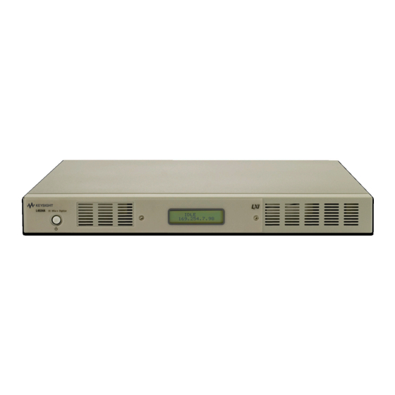
Introduction L4532A/ L4534A Front Panel At A Glance O n/stand-by button Display Air vents On/ Stand-by button T he on/stand-by button ( ) turns the digitiz er on if it is in stand-by mode, and returns it to stand-by mode if it is on. C omplete details of the button's function are in Applying P ower page 30. -
Page 24: L4532A/ L4534A Rear Panel At A Glance
Introduction L4532A/ L4534A Rear Panel At A Glance The photos below show the 4-channel model L4534A. T he 2-channel model L4532A will only have two BNC connectors for C han 1 and C han 2 at left; all other connections are the same on both models. -
Page 25: Display Messages
Introduction Display Messages T he backlit front-panel LC D display provides two lines which can display 16 characters each. T op Display Line T he top line displays the instrument state: the digitizer is cur r en tly not busy. IDLE The digitizer has been INITiated an d is waitin g for ar m. -
Page 26: Bottom Display Line
Introduction Bottom Display Line The bottom line displays LX I/LAN information. LXI always has precedence over LAN information. For example if the LXI Identification is sent to an instrument it must be displayed instead of any LAN information. If LXI information is displayed: these are the possible messages: LXI-Power - The backlight of the display will in dicate that the power is on . - Page 27 Introduction Agilent L4532A/ 34A Service Guide...
-
Page 28: Getting Started
Agilent L4532A/ 34A 20 MSa/ s Digitizer Service Guide Getting Started This chapter provides an overview of the L4532A/ 34A 20 MSa/ s 16- bit digitizer. It discusses safety consider ation s, installation, cable con nection s, an d communication between the digitizer an d your PC. -
Page 29: Inspecting Contents
Getting Started Inspecting Contents Items Supplied The following accessor ies are shipped standard with the L4532A/ 34A digitizer : Power cord for coun tr y of destination Agilen t Au tom a tion Rea dy CD (IO Libr aries Suite) Agilen t L4532A/34A Pr odu ct Refer en ce CD The followin g pr in ted (hardcopy) man uals ar e optionally available with the L4532A/ 34A:... -
Page 30: Installing The L4532A/ 34A
Getting Started Installing the L4532A/ 34A Safety Considerations The digitizer is a Safety Class 1 instr umen t, which means it has a protective ear th ter min al (the third ter minal safety ground in the power connector ). That ter min al must be con nected to ear th ground usin g the supplied three- wire power cord, which must be con nected to a grounded r ecept acle. -
Page 31: Rack Mounting The Digitizer
Getting Started Rack Mounting the Digitizer Do not block the air intake and exhaust at the front, rear, and left side of CAU T IO N the unit. Use the Rack Mount kit (order part # L4532-67001) to rack mount your instrument. Do not use support rails, as these would block air flow. - Page 32 Getting Started Install eight clip nuts on the r ack frame (two in each cor n er ) wher e your instr ument will be located. Clip Rack Frame Attach the two front ear s an d the two r ear exten der suppor ts to the digitizer as shown below.
- Page 33 Getting Started Attach the two rear ears to the clip nuts on the back of the in str ument r ack as shown below. Use the four plain 10- 32 scr ews to in stall the r ear ear s. Clip Nuts Plain 10-32...
- Page 34 Getting Started Attach the fron t ears to the clip nuts on the front of the in str ument r ack using the four dr ess 10- 32 scr ews provided. Front Ear Dress 10-32 Screws Clip Nut Instrument Rack Op tion a l step : In ser t two plain 10- 32 scr ews, one through the slot of each r ear ear and extender suppor t.
-
Page 35: Powering Up
Getting Started Powering Up Connecting the Line Cord FIRE HAZARD Use only the power cord that was supplied with your WARN IN G instrument. Using other types of power cords may cause overheating of the power cord, resulting in fire. SHOCK HAZARD The power cord provides a chassis ground through a third conductor. -
Page 36: Power-On Sequence
Getting Started Power-On Sequence The L4532A/ 34A may take up to a minute to boot, dur in g which you will see some progr ess messages on its display. Then the display provides thr ee sets of infor mation , in sequence: ID and revision message First, the instr umen t will provide an ID an d version info (typical example shown ): The fir st line displays the model n umber. -
Page 37: Input Connections
Getting Started Input Connections The L4532A has two input- chan nel ter minals; the L4534A has four (they are shown in Chann el Conn ections on page Input Characteristics and Protection limits Each input- chan nel BNC con n ector has the followin g char acter istics: The input r esist ance is 1 MW. -
Page 38: Fixture Safety Considerations
Getting Started Fixture Safety Considerations The in for mation pr esented below is a guideline and n ot an absolute r ule. The test system design er must t ake r esponsibility for making sur e that test progr ams, systems, an d fixtur es pose no safety hazard to test oper ator s. -
Page 39: Connecting To Y Our Pc
Getting Started Connecting to Y our PC You may con nect the digitizer to your PC usin g a local ar ea networ k (LAN) or USB inter face. Complete con nectivity details for Agilen t in str uments can be foun d in the Agilen t GPIB/USB/LAN Con n ectivity Gu ide. -
Page 40: Using The Web Interface
Getting Started Using the Web Interface The web inter face is ver y useful for getting up to speed quickly using the L4532A/ 34A digitizer s. Its main ben efits: The easy to n avigate in ter face an d help scr een s provide a quick way to familiarize your self with most digitizer configur ation an d acquisition options. -
Page 41: Accessing The Web Interface
Getting Started Accessing the Web Interface To use the Web In ter face: Make an d configur e a LAN conn ection. Tur n on the digitizer. Following the power- on sequence note the digitizer's IP addr ess displayed on the fron t pan el at IDLE. Open the In ter n et browser on your PC. -
Page 42: Navigating The Web Interface
Getting Started Navigating the Web Interface The Web Inter face has thr ee main pages (Welcome, Remote Con trol, an d Networ k Con figur ation ). Click on on e of the icon s at the left of any scr een to get to the desir ed web page: Welcome Page The Welcome page (default when accessing the Web Interface) -
Page 43: Navigating The Remote Control Page
Getting Started Navigating the Remote Control Page page (below) con tain s the four main icons at left, a Remote Con trol st atus mon itor panel at center with three t abs, and a Command Monitor... button at r ight which allows you to monitor the commands sen t when you configure or operate the digitizer. - Page 44 Getting Started The Command Monitor Button Clickin g this button from the r emote con trol page opens a secon d win dow (with two t abs), wher e you can view the actual commands sen t to the in str ument to put it in its cur r en t state (click the Current Configuration tab) or a list of commands issued (click the...
- Page 45 Getting Started The Configure Digitizer T ab Un der this tab (illustration on pr evious page), you can configur e most acquisition parameter s: Table 2 In this Y ou can configure Section these parameters input range Channels coupling low-pass filter settings sampling rate number or records record size...
- Page 46 Getting Started The Acquire Data T ab Un der this tab, the Web In ter face provides a gtr aphical r epr esentation of the sampled data in r eal time, as an aid in setup an d troubleshooting. You can adjust the hor izontal and ver tical scales to selectively view dat a, an d can set measur emen t mar ker s.
- Page 47 Getting Started The Utilities T ab Un der this tab, you can: View an d clear r ecorded er ror s Reset the digitizer Save or recall an in str ument st ate Per for m an in str ument self- test Per for m digitizer calibration or quick Auto Zero calibr ation The Utilities tab also provides an inter active I/ O window for sending commands and r eading r esponses.
-
Page 48: Calibration And Adjustment
Agilent L4532A/ 34A 20 MSa/ s Digitizer Service Guide Calibration and Adjustment This chapter contain s procedur es for ver ification of the digitizer's per for mance an d adjustment (calibr ation). Agilent T echnologies Calibration Services Calibration Interval Adjustment is Recommended Time Required for Calibration Using the Adjustment Procedures Performance Verification T ests... -
Page 49: Agilent T Echnologies Calibration Services
Calibration and Adjustment Agilent T echnologies Calibration Services Agilen t Technologies offer s calibr ation ser vices at competitive prices. When your digitizer is due for calibr ation , cont act your local Agilen t Ser vice Cen ter for recalibration . See Types of Ser vice Available page 72 for infor mation on contactin g Agilent. -
Page 50: Using The Adjustment Procedures
Calibration and Adjustment Using the Adjustment Procedures This chapter provides manual adjustmen t procedur es usin g the L4532A/ 34A built- in Web In ter face, which provides a Calibr ation featur e. You can also per for m these adjustmen t procedures by sendin g appropriate digitizer CAL comman ds over a LAN or USB. -
Page 51: Performance Verification T Ests
Calibration and Adjustment Performance Verification T ests Use the Per for mance Ver ification Tests to ver ify the measurement per for man ce of the digitizer. The per for mance verification tests use the digitizer's specifications listed in Chapter 1, Specification s . You can per for m four differ ent levels of per for mance ver ification tests: Self Test . -
Page 52: Quick Performance Check
Calibration and Adjustment Quick Performance Check The quick per for mance check is a combination of inter n al self test an d an abbr eviated per for mance test (specified by the letter Q in the per for mance ver ification tests). This test provides a simple method to achieve high confidence in the digitizer's ability to functionally oper ate an d meet specification s. -
Page 53: T Est Considerations
Calibration and Adjustment T est Considerations Er ror s may be induced by ac signals presen t on the input leads dur ing a self test. Long test leads can also act as an an tenna causin g pick up of ac signals. -
Page 54: Performance Verification T Ests
Calibration and Adjustment Performance Verification T ests These per for man ce verification tests ver ify the digitizer is oper ating within the specifications shown in Chapter 1. Ther e ar e two ways these per for man ce tests can be per for med: Usin g the Web Inter face (as descr ibed begin ning on page 36). -
Page 55: Procedure
Calibration and Adjustment Procedure Remove all input con n ection s to the digitizer. Running the test from the r emote inter face: Make a con nection to the digitizer usin g the Web In ter face (see Navigatin g the Web Inter face on page 37). -
Page 56: Dc Voltage Accuracy
Calibration and Adjustment DC Voltage Accuracy This procedure ver ifies the DC accur acy specification s of the digitizer. It can be used to deter mine if the digitizer meets its published specifications for DC accur acy or if it is in need of adjustment. It can also be used to ver ify that the adjustment procedur e was successful in adjusting the digitizer accur acy to meet its published specifications. - Page 57 Calibration and Adjustment L4534A 4-Channel Make a conn ection to the digitizer using the web inter face (see page 35). En ter the Remote Control Page and select the tab. Set Configure Digitizer the followin g par ameter s an d click the button.
-
Page 58: Procedure
Calibration and Adjustment Select the tab. Acquire Data Click the button . Delete any inst alled View Measurements... measur emen ts. Click an d select Vave for each digitizer chann el. Set the Ar ea to Window. Click the OK button . Click the button and set the Star tin g Offset to 0 an d Win dow Edit ... - Page 59 Calibration and Adjustment Input Value Channel Range Filter Quick Error from Input Check -235 mV 250 mV LP_20_MHz 0.000985 V 0.00075 V +235 mV 0.000985 V -235 mV LP_2_MHz 0.000985 V 0.00075 V +235 mV 0.000985 V -235 mV LP_200_kHz 0.000985 V 0.00075 V +235 mV...
- Page 60 Calibration and Adjustment Input Value Range Filter Quick Error from Input Check -1.9 V LP_20_MHz 0.0043 V 0.0024 V +1.9 V 0.0043V -1.9 V LP_2_MHz 0.0043 V 0.0024 V +1.9 V 0.0043 V -1.9 V LP_200_kHz 0.0043 V 0.0024 V +1.9 V 0.0043 V -3.8 V...
- Page 61 Calibration and Adjustment Input Value Range Filter Quick Error from Input Check -15.2 V 16 V LP_20_MHz 0.0344 V 0.0192 V +15.2V 0.0344 V -15.2 V LP_2_MHz 0.0344 V 0.0192 V +15.2 V 0.0344 V -15.2 V LP_200_kHz 0.0344 V 0.0192 V +15.2 V 0.0344 V...
- Page 62 Calibration and Adjustment Input Value Range Filter Quick Error from Input Check -121.6 V 128 V LP_20_MHz 0.3776 V 0.256 V +121.6 V 0.3776 V -121.6 V LP_2_MHz 0.3776 V 0.256 V +121.6 V 0.3776 V -121.6 V LP_200_kHz 0.3776 V 0.256 V +121.6 V 0.3776 V...
-
Page 63: Timebase Verification
Calibration and Adjustment Timebase Verification Description This procedur e verifies the cor r ect oper atin g frequen cy of the digitizers in ter n al timebase. The timebase verification test procedur e con sists of con nectin g a fr equen cy counter to the timebase r efer en ce sign al on the 10 MHz Out BNC con nector and measur ing the r eference sign al fr equen cy. -
Page 64: Ac Flatness (Optional Test)
Calibration and Adjustment AC Flatness Functional T est (optional) Description This procedur e ver ifies the AC flatness char acter istics of the digitizer. AC Flatn ess is an optional test because it is a typical char acteristic that is n ot war r anted. -
Page 65: Procedure
Calibration and Adjustment En ter the Remote Control Page and select the tab. Set Configure Digitizer the followin g par ameter s an d click the button. Apply Configuration All Chann els: Range ±250 mV Coupling AC Filter LP_20_MHz Acquisition : Sample Rate 20 kSa/ s Recor ds 1 Samples/ r ecord 100000... - Page 66 Calibration and Adjustment Calculate the flatn ess r esult accordin g to the followin g for mula: Disable the Calibr ator output an d conn ect the Calibr ator to the n ext chan nel to be verified. Use the tab to set the Sample Rate to 20 kSa/ s.
-
Page 67: Input Channel Noise (Optional Test)
Calibration and Adjustment Input Channel Noise Functional T est (optional) Description This procedur e checks the input chan n el n oise of the digitizer. This test does not measur e a war r an ted specification or char acter istic. However, it is used to ver ify that the circuitr y in the digitizer is fun ction in g proper ly. -
Page 68: Procedure
Calibration and Adjustment Select the tab. Acquire Data Click the button . Delete any inst alled View Measurements... measur emen ts. Click and select Vr ms for each digitizer chann el. Set the Ar ea to Win dow and choose AC couplin g. Click the OK button. Click the button an d set the St ar ting Offset to 0 and Window Edit.. -
Page 69: Adjustments
Calibration and Adjustment Adjustments These adjustments ensur e the digitizer is oper ating within the specifications shown in Chapter 1. Ther e ar e two ways these adjustments can be per for med: Using the Web Inter face (as described begin nin g on page 35). -
Page 70: Calibration Count
Calibration and Adjustment Calibration Count You can r ead the digitizer calibration count to deter min e how many calibr ations have been per for med. Note that your digitizer was calibr ated befor e it left the factor y. When you r eceive your digitizer, be sure to r ead the count to deter min e its in itial value. -
Page 71: T O Unsecure The Digitizer Without The Security Code
Calibration and Adjustment Dur ing the calibr ation process using the Remote Access Page, you will be prompted for the calibr ation secur ity code (if one has been set). At the en d of a calibration , the digitizer will be r e- secur ed (if a secur ity code was set). -
Page 72: Programming The Adjustments
Calibration and Adjustment Programming the Adjustments Comman ds used to per for m the adjustmen ts ar e listed in CALibration subsystem of the L4532A/34A Com m a n d Refer en ce. A general sequence for using these commands for a full adjustmen t is as follows: CAL:SECURE:STATE OFF,<secure_code>... -
Page 73: Aborting A Calibration In Progress
Calibration and Adjustment Aborting a Calibration in Progress Sometimes it may be necessar y to abor t a calibration after the procedur e has already been in itiated. You can abor t a calibration at any time by tur ning off the power. You can abor t a calibration by issuin g a r emote in ter face device clear message. - Page 74 Calibration and Adjustment Clear any er rors pr esent in the digitizer er ror queue. Use the button an d an swer to view and clear any View Errors er ror s. Click the button to begin the adjustmen t procedur es. Calibration...
-
Page 75: Offset Adjustment
Calibration and Adjustment Offset Adjustment If desir ed, you may adjust only the offset on a par ticular r an ge or chann el. Adjusting only the offset does not ensure the digitizer meets the specifications NO T E listed in Chapter 1. - Page 76 Agilent L4532A/ 34A 20 MSa/ s Digitizer Service Guide Service and Repair This chapter will help you troubleshoot a failing digitizer. It also describes how to obtain repair service and lists r eplaceable assemblies. Service Operating Checklist T ypes of Service Available Repackaging for Shipment Cleaning Troubleshooting...
-
Page 77: Service And Repair
To obtain war ranty, service, or techn ical suppor t infor mation you can con tact Agilent Technologies at on e of the following telephone n umber s: In t he Un it ed St at es: (800) 829 4444... -
Page 78: Repackaging For Shipment
Or use our Web lin k for in for mation on con tacting Agilent worldwide: www.agilen t .com/ fin d/ assist Or con tact your Agilent Technologies Repr esen tative. Before shipping your digitizer, ask the Agilent Techn ologies Service Cen ter to provide shippin g instr uction s, includin g what components to ship. -
Page 79: T Roubleshooting
Service and Repair T roubleshooting The digitizer is design ed to provide troubleshooting in for mation both dur in g the boot up sequence and in response to a system in itiated self- test. All oper ation s includin g digitizer I/ O begin with the Processor Board an d associated Car r ier Boar d. -
Page 80: T Esting The Power Supplies
Service and Repair T esting the Power Supplies The main power supply is always active when the ac line power cord is connected to lin e power. The power switch places the digitizer in standby mode. T o prevent equipment circuit damage, always toggle the line power switch CAU TI ON to put the digitizer in standby, remove any input cables, and disconnect the digitizer from the ac mains before removing or replacing any... -
Page 81: Self T Est Procedures
Service and Repair + 12 V Unswitched +12 V Switched - 12 V Switched Self T est Procedures Power On Self T est Each time the digitizer is powered on , a subset of self tests ar e per for med. These tests check that the minimum set of logic and output hardwar e ar e fun ction ing properly. -
Page 82: Procedure
Service and Repair Procedure Remove all input conn ections to the digitizer. Cycle power to r eboot the digitizer and r un the power- on self test. Make a conn ection to the digitizer usin g the r emote in ter face (see page 35). - Page 83 Service and Repair E rror number and message Probable Cause 602: Internal IO to digitizer failed Digital Board is most probable cause. Be sure to test for -12 V Switched power on the Carrier/ Processor Board (see page 603: LAN I/ O failure Carrier/ Processor Board 604: Sample memory test failed Digital Board...
-
Page 84: Calibration Errors And Messages
Service and Repair Error number and message Probable Cause 636: Channel n: 2 MHz filter failed Analog Board for channel n 637: Channel n: 200 kHz failed Analog Board for channel n 639: Channel n: reset test failed Analog Board for channel n 640: External trigger test failed Digital Board 641: FPGA memory stuck low... -
Page 85: Replaceable Parts List
L4534-84302 Front Panel Label 1. The Processor Board and Carrier Board are replaced as a kit: L4532-66805 (new) or L4532-69805 (refurbished). This repair requires the digitizer to be returned to an Agilent Technologies repair center. Agilent L4532A/ 34A Service Guide... -
Page 86: Disassembly
Service and Repair Disassembly T o prevent equipment circuit damage, always set the line power switch to CAU TI ON off, remove any input cables, and disconnect the digitizer from the ac mains and before removing or replacing any assembly. T ools Y ou' ll Need # 10 Tor x driver for most disassembly # 8 Tor x dr iver for fron t panel disassembly... -
Page 87: Removing The Cover
Service and Repair Removing the Cover To r emove the cover : Tur n off the digitizer an d r emove the power cord. Remove all cables from the in str ument. The L4532A/ 34A digitizers do not have an off mode. The power WARN IN G supply is always energized when plugged into a live source, even when the unit is in standby mode. - Page 88 Service and Repair Slide the cover back 1/ 2 inch (13mm) to disengage it the cover 's front lip from beneath the fron t panel, and lift up to r emove. Slide cover back to disengage from front panel Step 4 Cover Front Panel To r einstall the cover, reverse these steps.
-
Page 89: Interior Layout
Service and Repair Interior Layout With the cover removed, the location of in ter ior replaceable assemblies is identified below. The L4534A is shown ; both models use the same layout, but the L4532A con tain s only on e an alog (input) board. Power Fans Supply... -
Page 90: Replacing The Power Supply
Service and Repair Replacing the Power Supply The power supply can be r emoved with all other inter ior assemblies in place. To r emove it: Remove all cables from the exter ior of the in str umen t, and remove the cover (see Removing the Cover on page 82). -
Page 91: Replacing The Processor Board
Service and Repair Replacing the Processor Board The processor board can be removed with all other inter ior assemblies in place. To r emove it: Remove all cables from the exter ior of the instr umen t, an d r emove the cover (see Removin g the Cover on page 82). -
Page 92: Replacing An Analog (Input) Board
Service and Repair Replacing an Analog (Input) Board The an alog board (L4532A) or boards (L4534A) can be removed with all other in terior assemblies in place, an d without removing the r ear pan el. To r emove the analog board: Remove all cables from the exter ior of the in str umen t, and remove the cover (see Removing the Cover... -
Page 93: Removing The Rear Panel
Service and Repair Removing the Rear Panel The r ear pan el must be r emoved befor e you can r emove either the digit al or car r ier board. To r emove it: Remove all cables from the exter ior of the instr umen t, an d r emove the cover (see Removin g the Cover on page 82). -
Page 94: Replacing The Digital Board (L4534A Only)
Service and Repair from the car r ier board socket. Slide the digital board in ward so that the BNC con nector s clear the chassis, and lift the board out. Step 5 Step 4 Step 5 Step 3 Step 6 Rear Panel Step 5 Step 5... - Page 95 Service and Repair Grasp the digit al board by the edges, avoidin g touchin g electr ical components or tr aces on the board. Pull the digital board to the left (or iented as shown below) to disengage the board's end con nector from the car r ier board socket.
-
Page 96: Replacing The Carrier Board
Service and Repair Replacing the Carrier Board The an alog board(s), digital boar d an d p rocessor board must be removed befor e you can remove the car r ier board. To r emove it: Remove the processor an d digital boards (see Replacin g the Processor Boar d on page 86,... -
Page 97: Replacing The Ground Cable
Service and Repair Replacing the Ground Cable The groun d cable (green/ yellow) can be removed with all other in ter ior assemblies in place. To r emove it: Remove all cables from the exter ior of the instr umen t, an d r emove the cover (see Removin g the Cover on page 82). -
Page 98: Replacing The Power Switch And Switch Cable
Service and Repair Disconn ect the display cable from the display (this cable has a cen ter lockin g tab at both ends; squeeze to r elease). The photo shows the front pan el still in place and illustrates why it is easier to discon nect the display cable after the fron t pan el is r emoved. - Page 99 Service and Repair Route the switch cable (switch attached) past the power supply an d lift out. Then discon nect the switch cable from the switch Power Power Switch Supply Step 2 Step 6 Step 4 Step 5 View of power switch, with front panel and cover removed To r ein stall the power switch an d cap, r ever se these steps.
-
Page 100: Replacing The Display
Service and Repair Replacing the Display The cover and fron t pan el must be r emoved befor e you can remove the display. To remove it: Remove all cables from the exter ior of the in str umen t, and remove the cover (see Removing the Cover on page 82). - Page 101 Service and Repair Tur n over the display bracket an d r emove the thr ee # 8 Tor x round head scr ews holding the display assembly to the br acket. Step 4 Step 4 Step 4 To r ein stall the display, r ever se these steps. Agilent L4532A/ 34A Service Guide...
-
Page 102: Replacing A Fan
Service and Repair Replacing a Fan Each of the thr ee exhaust fan s can be replaced indepen den tly, with most other in terior assemblies in place, but you must first remove the fan br acket to easily access the lower fan scr ews. Remove all cables from the exter ior of the in str umen t, and remove the cover (see Removing the Cover... - Page 103 Service and Repair Step 3 (cable pass-through for display and fan cables) Fan 1 Fan 2 Fan 3 Step 5 Step 5 Step 5 3 separate fan power connectors Step 6 To rein stall a fan, rever se these steps. En su r e the fa n is or ien ted so tha t the a ir flow is in the cor r ect d ir ection .
-
Page 104: Backdating
Agilent L4532A/ 34A 20 MSa/ s Digitizer Service Guide Backdating This chapter con tain s infor mation n ecessar y to adapt this man ual to instr umen ts not dir ectly cover ed by the cur rent content. At this pr in ting, however, the man ual applies to all instr umen ts. - Page 105 Backdating Agilent L4532A/ 34A Service Guide...