Sign In
Upload
Download
Table of Contents
Contents
Add to my manuals
Delete from my manuals
Share
URL of this page:
HTML Link:
Bookmark this page
Add
Manual will be automatically added to "My Manuals"
Print this page
×
Bookmark added
×
Added to my manuals
Manuals
Brands
Stratasys Manuals
3D Printers
FDM 2000
Manual
Stratasys FDM 2000 Manual
Hide thumbs
1
2
3
4
5
6
7
8
9
10
11
12
13
14
15
16
17
18
19
20
21
22
23
24
25
26
27
28
29
30
31
32
33
34
35
36
37
38
39
40
41
42
43
44
45
46
47
48
49
50
51
52
53
54
55
56
57
58
59
60
61
62
63
64
65
66
67
68
69
70
71
72
73
74
75
76
77
78
79
80
81
82
83
84
85
86
87
88
89
90
91
92
93
94
95
96
97
98
99
100
101
102
103
104
105
106
107
108
109
110
111
112
113
114
115
116
117
118
119
120
121
122
123
124
125
126
127
128
129
130
131
132
133
134
135
136
137
138
139
140
141
142
143
144
145
146
147
148
page
of
148
Go
/
148
Contents
Table of Contents
Troubleshooting
Bookmarks
Table of Contents
Section 1
Introduction
About this Manual
Purpose
Conventions
Materials
Bass
Finishing the Part
Capabilities
Requirements
Installation
Table of Contents
FDM 2000/3000/8000 Procedures
Calibration
Toolpath Width Calibration
T10 Tip Offset Calibration
Creating a Calibration Box
FDM 2000/3000/8000 Usage
Changing the FDM Head
Removing an FDM Head from the FDM F2/3/8000-20
Attaching an FDM Head
Removing Backflow from the Head
Setting Modeling Temperatures
Changing the FDM Tip
Attaching FDM Tips to the FDM Head _ F2/3/8000-25
Changing Spools of Modeling Material
Removing an Empty Spool of Material _ F2/3/8000-27
Removing a Mounted Spool of Material F2/3/8000-27
Mounting a Spool of Material
Enabling the Auto Shutoff
Dry Filament Measurement Procedure
Drying P400 ABS Filament
Replacing the Foam Foundation
Removing the Foundation
Attaching the Foundation
Positioning the FDM Head
FDM 2000/3000/8000 Maintenance
Equipment Required
Cleaning the FDM Head
Daily Cleaning
Periodic Maintenance
Checking the Operation of the Filament Sensorf2/3/8000-39
Cleaning and Lubricating the Lead Screws
FDM 2000/3000/8000 Troubleshooting
Torque Limiting
Section 2
Introduction to Waterworks P400/500 Soluble Release
Preparing the FDM
Changing the Watlow Temperatures
Changing the FDM Tip
Attaching FDM Tips to the FDM Head
Removing an FDM Tip from the FDM Head
Changing Spools of P400/500 Material
Mounting a Spool of Material
Removing an Empty Spool of Material
Removing a Mounted Spool of Material
Downloading Insight and Button Files
Calibrating for Soluble Material
Removing Soluble Supports with the Ultrasonic Cleaner
Advertisement
Quick Links
1
Introduction
2
Materials
3
Capabilities
4
Section 1
5
Changing the Fdm Head
6
Downloading Insight and Button Files
Download this manual
Introduction
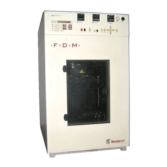
FDM 2000 / 3000 / 8000
Release 2.0
Stratasys Document no. 105208-0001
Rev. B
Table of
Contents
Previous
Page
Next
Page
1
2
3
4
5
Advertisement
Chapters
Section 1
14
Section 2
81
Table of Contents
Need help?
Do you have a question about the FDM 2000 and is the answer not in the manual?
Ask a question
Questions and answers
Related Manuals for Stratasys FDM 2000
3D Printers Stratasys FDM Vantage Series User Manual
(132 pages)
3D Printers Stratasys FDM Titan User Manual
(142 pages)
3D Printers Stratasys FDM 200mc User Manual
(68 pages)
3D Printers Stratasys FDM 3000 Manual
(148 pages)
3D Printers Stratasys Fortus 360mc Quick Reference Card
(2 pages)
3D Printers Stratasys FORTUS 360mc Manual
(162 pages)
3D Printers Stratasys F170 Operation And Maintenance Manual
F123 series shared office 3d printers (91 pages)
3D Printers Stratasys F170 User Manual
F123 series shared office 3d printers (230 pages)
3D Printers Stratasys F900 User Manual
3d production system (153 pages)
3D Printers Stratasys F120 User Manual
Shared office 3d printer (217 pages)
3D Printers Stratasys F120 Site Preparation Manual
(17 pages)
3D Printers Stratasys F770 User Manual
(262 pages)
3D Printers Stratasys F123 Series Manual
Shared office 3d printing system (21 pages)
3D Printers Stratasys F190 CR Site Preparation Manual
(22 pages)
3D Printers Stratasys F370 CR Site Preparation Manual
(22 pages)
3D Printers Stratasys F3300 User Manual
(236 pages)
This manual is also suitable for:
Fdm 3000
Fdm 8000
Table of Contents
Print
Rename the bookmark
Delete bookmark?
Delete from my manuals?
Login
Sign In
OR
Sign in with Facebook
Sign in with Google
Upload manual
Upload from disk
Upload from URL


Need help?
Do you have a question about the FDM 2000 and is the answer not in the manual?
Questions and answers