Table of Contents
Advertisement
Quick Links
Advertisement
Table of Contents

Subscribe to Our Youtube Channel
Related Manuals for Keysight Technologies U3022AE10


Summary of Contents for Keysight Technologies U3022AE10
- Page 1 Keysight Technologies U3022AE10 Multiport Test Set Extension Notice: This document contains references to Agilent. Please note that Agilent’s Test and Measurement business has become Keysight Technologies. For more information, go to www.keysight.com. User’s and Service Guide...
- Page 2 INCLUDING BUT NOT LIMITED TO THE agreement and written consent the public. Accordingly, Keysight IMPLIED WARRANTIES OF from Keysight Technologies, Inc. as provides the Software to U.S. MERCHANTABILITY AND FITNESS FOR governed by United States and government customers under its A PARTICULAR PURPOSE.
-
Page 3: Table Of Contents
Table of Contents Keysight U3022AE10 Multiport Test Set Extension User's and Service Guide Introduction ............. . . 8 Description . - Page 4 Table of Contents System Operational Check ..........32 Equipment Setup .
- Page 5 Table of Contents Verification Limits ............61 Cal Kit Operational Check Procedure .
- Page 6 Table of Contents Safety ............. .93 Acoustic Statement (European Machinery Directive).
- Page 7 U3022AE10...
-
Page 8: Introduction
U3022AE10 Introduction Introd uction This document describes how to use and service the U3022AE10 Multiport Test Set. 4-Port PNA-L with U3022AE10* Figure 1 Shown in older color format. Keysight U3022AE10 User's and Service Guide... - Page 9 U3022AE10 Introduction Figure 2 2-Port PNA-X with U3022AE10* * Shown in older color format. Figure 3 4-Port PNA-X with U3022AE10* * Shown in older color format. Keysight U3022AE10 User's and Service Guide...
-
Page 10: Description
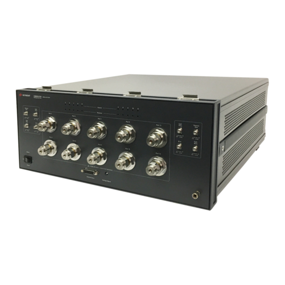
U3022AE10 Description Description The U3022AE10 is a Multiport Test Set designed to be configured with a 2 or 4-Port PNA, PNA-L or PNA-X for a 12 or 14-Port network analyzer measurement system. • 10 test ports (3.5 mm male connectors) •... -
Page 11: Pna And Pna-X Receiver Compression Note
Ensure the network analyzer has the latest version of firmware installed. The following web site links will provide necessary information needed: •Network Analyzer Firmware - http://na.support.keysight.com/pna/firmware/firmware.html •U3022AE10 Test Set Files - http://na.support.keysight.com/multiport/testsetsupport.html Keysight U3022AE10 User's and Service Guide... -
Page 12: Available Options
Extended frequency range from 300 kHz to 26.5 GHz. Rack Mounting Kits Installation instructions are included in the option package. • U3022AE10-1CM, Rack Mount Kit without Handles (1CM114A*) 5063-9216 • U3022AE10-1CN, Front Handle Kit (1CN103A*) 5063-9229 • U3022AE10-1CP, Rack Mount Kit with Handles (1CP106A*) 5063-9236... -
Page 13: Network Analyzer Interface Kit Options
Available Options Network Analyzer Interface Kit Options The U3022AE10 requires one of the following kits to interface the test set with your network analyzer. The interface kit model option includes the hard ware lock-link and cable kit listed in Table 3. -
Page 14: General Specifications
• U3022AE10 maximum power is 350 W. This is a Safety Class I product (provided with a protective earthing ground incorporated in the power cord). The mains plug shall be inserted only into a socket outlet provided with a protective earth contact. -
Page 15: Environmental Requirements
Table 4 Instrument Dimensions Model Weight Height Wid th Depth 11.4 kg 19.1 cm 42.5 cm 43.2 cm U3022AE10 (25 lb) (7.5 in) (16.7 in) (17 in) Keysight U3022AE10 User's and Service Guide... -
Page 16: Frequency Range And Power Levels
+27 dBm RCVR A IN and B IN +12 dBm Damage Power Levels to U3022AE10 Access and Test Ports: Max Level to Port 1 & 2 Test Ports +30 dBm Refer to your analyzer’s specifications to determine the maximum input power levels for the access and test ports, or to optimize the power levels in the receivers. -
Page 17: Typical Reflection Tracking
500 MHz to 3.2 GHz 3.2 GHz to 10 GHz 10 GHz to 16 GHz 16 GHz to 20 GHz 20 GHz to 24 GHz 24 GHz to 26.5 GHz a. Upper end is limited to 20 GHz. Keysight U3022AE10 User's and Service Guide... -
Page 18: Front And Rear Panel Features
Set connected to the PNA-X will never have an "ON" Active LED. Instead, the last Test Set in the I/O cable chain will be the Test Set showing the "Active LED" status for all. Keysight U3022AE10 User's and Service Guide... - Page 19 Fuse (F 5 A/250V, 2110-0709) UL listed and CSA certified For continued protection against fire hazard replace line fuse only with same type and rating. The use of other fuses, circuit breakers or materials is prohibited. Keysight U3022AE10 User's and Service Guide...
- Page 20 U3022AE10 Front and Rear Panel Features Figure 6 Line Module and Fuse Verify that the premise electrical voltage supply is within the range specified on the instrument. Keysight U3022AE10 User's and Service Guide...
-
Page 21: Hardware Lock-Link Kit Installation (U3021-60001)
2. Remove the feet from the bottom of the analyzer. 3. Remove the 2 lower standoffs from the rear panel on the analyzer. Figure 7 Rear Bottom Feet Standoffs (x2) Feet (x4) Keysight U3022AE10 User's and Service Guide... - Page 22 5. Remove the top two standoffs from the rear panel on the test set. 6. Install the top left and right rear lock-links from the kit (5063-9253) using screws (0515-1244). Figure 9 Install Rear Lock-links to the Test Set 5022-2816 5022-2818 Keysight U3022AE10 User's and Service Guide...
- Page 23 “Network Analyzer Interface Kit Options” on page 13 “Contacting Keysight” on page 94 for ordering information. • PNA-L - 5023-0132 (Kit includes lock-links and screws) • Test Set - 5063-9253 (Kit includes lock-links and screws). Keysight U3022AE10 User's and Service Guide...
-
Page 24: Hardware Lock-Link Kit Installation (U3021-60002)
PNA or PNA-X. 2. Remove the feet from the bottom of the analyzer. 3. Remove the 2 lower standoffs from the rear panel on the analyzer. Figure 12 Rear Bottom Feet Standoffs (x2) Feet (x4) Keysight U3022AE10 User's and Service Guide... - Page 25 6. Install the two rear lock-links onto the Test Set. Looking at the front panel, the N5242-20138 is the right foot and the N5242-20139 is the left foot. Two screws (0515-2317) are included with this option. Figure 14 Install Lock-links to Test Set N5242-20139 N5242-20138 0515-2317 Keysight U3022AE10 User's and Service Guide...
- Page 26 • PNA or PNA-X- 5023-0132 (Kit includes lock-links and screws) • Test Set - N5242-20138 (right foot) and N5242-20139 (left foot) and screw (0515-2317) for use with the PNA or PNA-X. Keysight U3022AE10 User's and Service Guide...
-
Page 27: N5232A/B Rf Interface Cable Connections
Each end of the interconnect RF cables have a different length from the bend. When connecting the RF Interconnect cables be sure that the longer end (from the bend) is connected to the analyzer. Keysight U3022AE10 User's and Service Guide... - Page 28 CPRL THRU U3022-20038 RCVR D IN B IN indicates the final two digits of the part number for each cable. Figure 19 14-Port Interface Connections Figure 17 Port 13 Port 14 Port 2 38 37 Keysight U3022AE10 User's and Service Guide...
-
Page 29: N5222A/B And N5242A/B Rf Interface Cable Connections
Port 1, CPLR THRU CPLR THRU U3042-20046 Port 2, CPLR THRU CPLR THRU U3042-20047 Port 2, RCVR B IN B IN U3042-20048 Port 2, SOURCE OUT SOURCE OUT U3042-20049 Port 2, CPLR ARM CPLR ARM Keysight U3022AE10 User's and Service Guide... - Page 30 The cables must be connected in the numeric order listed in Table 9 on page Figure 18 12-Port RF Interface Cable Connections 42 44 47 49 Figure 19 14 Port RF Interface Cable Connections Port 13 Port 14 Keysight U3022AE10 User's and Service Guide...
-
Page 31: Test Set I/O Cable Installation
Test Set I/O Cable Installation 1. Connect the analyzer’s Test Set I/O cable (N4011-21002) to the Test Set Interface connector on the rear panels, similar to Figure 20. Figure 20 Test Set I/O Cable Connection Keysight U3022AE10 User's and Service Guide... -
Page 32: System Operational Check
Figure 25 on page 35 The trace ripple (peak-peak variation will be higher than when using an ECal Module due to variation in your Short’s performance. If response is in question perform “Cal Kit Operational Check” on page Keysight U3022AE10 User's and Service Guide... - Page 33 U3022AE10 System Operational Check Figure 21 Typical Reflection Response Ports 1-2 (Standard) Figure 22 Typical Reflection Response Ports 1-2 (Option 001) Keysight U3022AE10 User's and Service Guide...
- Page 34 U3022AE10 STD RF Diagram Mechanical Switches Port 3 Port 5 Port 7 Port 9 Port 11 Port 12 Port 10 Port 8 Port 6 Port 4 Figure 24 Typical Reflection Response Ports 3-12 (Standard) Keysight U3022AE10 User's and Service Guide...
- Page 35 Port 2 Port 1 Port 13 Port 14 U3022AE10 STD RF Diagram Mechanical Switches Port 3 Port 5 Port 7 Port 9 Port 11 Port 12 Port 10 Port 8 Port 6 Port 4 S1212 Keysight U3022AE10 User's and Service Guide...
-
Page 36: Controlling The Test Set With N5222A/B, N5232A/B Or N5242A/B
The following key conventions are used throughout this document. • [HARDKEYS] are labeled front panel keys SOFTKEYS are indicated on the instrument display • • (Italicized in parenthesis) are menu paths for the "B" model analyzer. Keysight U3022AE10 User's and Service Guide... -
Page 37: Multiport Mode (Option 551)
Utility > System > Configure > Multiport Capability -OR- (Instrument > Setup > External Hardware > Multiport > Multiport Configuration...). 2. Select U3022AE10 (12-Port System) from the drop-down menu and select Restart as a multiport PNA with this testset > OK. The analyzer will restart the network application with the test set interface features. -
Page 38: External Test Set Control Feature
This menu will allow the physical Ports 1 thru 8 to be identified as any port for your convenience. For example, Port 5 can be re-named Port 2. The External Test Set Control-U3022AE10 also allows control of the DUT control lines, refer to “Control Lines”... -
Page 39: Trace Measure S-Parameter
Trace/Chan > Trace > New Trace -OR- (Instrument > Trace > New Trace). The dialog box allows the selection of any of the 144 S-Parameters. New S-Parameter Measurement Figure 30 Keysight U3022AE10 User's and Service Guide... - Page 40 In the search menu type “Multiport and Balanced.” Figure 31 Selecting Balanced Measurements Receivers Tab: The S-Parameter measurements can be ratioed with selectable Denominators for each port and receiver. Refer to the standard documentation for more information. Figure 32 Receiver Measurements Keysight U3022AE10 User's and Service Guide...
-
Page 41: Sweep Setup For Multiport And Standalone Modes
1. Select [Sweep] > Sweep Setup > Timing. 2. Select Timing tab. 3. Select Sweep Mode: Stepped. 4. Deselect Time: Auto Sweep Time. 5. Set Dwell Time > Apply > OK. Figure 34 Sweep Setup, N52xxB Keysight U3022AE10 User's and Service Guide... -
Page 42: Rf Path Configuration With Option 029
Save > User Preset > Save current state as User Preset. Do not use the factory Preset (User Preset Off); the analyzer will return to Option 029 path configuration. Figure 35 RF Path Configuration Keysight U3022AE10 User's and Service Guide... -
Page 43: N-Port Calibration
Response > Cal Wizard > Characterize ECal Mod ule -OR- (Response > Cal > Other Cals > ECal...). 2. Follow the prompts and save the ECal characterization file. Refer to the Help menu for characterizing information. Figure 36 ECal Characterization and Calibration Wizard Keysight U3022AE10 User's and Service Guide... - Page 44 If measurement errors occur, ensure the newest version of firmware is installed on the analyzer. Measurement errors can be a result of firmware algorithms. Consult with Keysight Service or firmware web page for the latest firmware revisions and history at http://na.support.keysight.com/pna/firmware/firmware.html Keysight U3022AE10 User's and Service Guide...
-
Page 45: Interface Control Mode
• Control data is sent in the following order and this order cannot be changed: Refer to the Help menu. 1. GPIB Interface 2. Material Handler Interface 3. Test Set Interface 4. Dwell Time Keysight U3022AE10 User's and Service Guide... -
Page 46: How To Access Interface Control Settings
The analyzer includes the Interface Control application and rear panel connection. Please review this application before connecting the test set to the network analyzer. Information regarding this application can be found in the Help menu, Interface Control. Figure 39 Interface Control Application Keysight U3022AE10 User's and Service Guide... -
Page 47: Using Interface Control Mode
The quantity of Test Set I/O entries that can be entered is limited by the available memory of the analyzer. Address and Data example: addr.data (3) 16.1 32.2 Keysight U3022AE10 User's and Service Guide... - Page 48 Word Pad. Applies the settings and closes the dialog box. Cancel: Does not apply changes that were made and closes the dialog box. Help: Provides additional information for using the interface control application. Keysight U3022AE10 User's and Service Guide...
-
Page 49: Scpi Control Mode
To access the Command Processor select Utility > System > Configure > SICL/GPIB/SCPI -OR- (System Setup > Remote Interface > SCPI Monitor Input > Show SCPI Parser Console), then check the SCPI Command Processor Console box. Figure 41 Command Console for 'A' Model Analyzers Keysight U3022AE10 User's and Service Guide... -
Page 50: Scpi Command Processor Console
PNA-X control capability than Method 2. The following example shows two executable commands needed to create an S-parameter measurement on your Multiport system. Method 1 - Using GPIB/SCPI Command Values Figure 43 Keysight U3022AE10 User's and Service Guide... - Page 51 Address and Data values are separated by a comma. Commands should be separated by a new line, or carriage return. For example: CONT:EXT:TEST:DATA <address>,<data> CONT:EXT:TEST:DATA 0,0 Example: CONT:EXT:TEST:DATA 0,0 Method 2 - Using Test Set Address and Data Values Figure 44 Keysight U3022AE10 User's and Service Guide...
-
Page 52: Address And Data Values
Two separate commands must to be sent, you may use the same dialog box. The entry will be 0.3 in one command line, and 16.48 in the second line. Table 11 Test Port Address and Data Values Address Source Path Receiver Path Data Ports Ports Keysight U3022AE10 User's and Service Guide... - Page 53 Address and Data Values Figure 45 Address and Data Example 1 (Port 3 and 11) Keysight 2-Port Port 1 0.81 Port 3 Port 11 Port 5 Port 7 Port 9 Receiver Port Source Port Keysight U3022AE10 User's and Service Guide...
-
Page 54: Control Lines
100 mA (each line) Control Line DC resistance < 10 Ω (each line) Voltage Range: Positive Input 0 to +5 V Negative Input –5 to 0 V Internal Variable Voltage +2 to +5 V Keysight U3022AE10 User's and Service Guide... - Page 55 Internal voltage output, adjusted with the trimmer on the rear panel. Positive Input Connection for internal (pin 12) or external positive voltage supply. Negative Input Connection for ground (pin 15) or external negative voltage supply. ground terminal Keysight U3022AE10 User's and Service Guide...
-
Page 56: Internal Voltage Supply Configuration
You may only connect pin 12–13, and pin 14–15; damage may result if any other paths are short-circuited. Figure 47 Internal DC Power Configuration (rear panel view) Line 1 Line 2 (Rear Panel View) TO DUT (Only required Lines) Line 8 2 to 5 Vdc TEST SET Keysight U3022AE10 User's and Service Guide... -
Page 57: External Voltage Supply Configuration
Test Set to the DUT and External DC Power Supply Line 1 Line 2 (Rear Panel View) TO DUT (Only required Lines) DC Power Supply Line 8 2 to 5 Vdc Positive: 0 to 5 Vdc Negative: 5 to 0 Vdc TEST SET Keysight U3022AE10 User's and Service Guide... -
Page 58: Setting The Control Lines With Address And Data Values
DUT Control Line 6 set to logic low or connected to Pin 14 DUT Control Line 7 set to logic low or connected to Pin 14 DUT Control Line 8 set to logic low or connected to Pin 14 Keysight U3022AE10 User's and Service Guide... - Page 59 3. The SUM of the <data> values = 6 4. Front panel analyzer Interface Control Mode line entry = 112.6 > OK. Since all control lines have the same <address>, only one "<address>.<data>" command line is needed to control all 8 lines. Keysight U3022AE10 User's and Service Guide...
-
Page 60: Cal Kit Operational Check
N5232A/B 4-Port Network Analyzer (Option 416 and 551) or N5242A/B 4-Port Network Analyzer (Option 400 and 551) or N5242A/B 2-Port Network Analyzer (Option 200 and 551) Set of interconnect cables (analyzer to test set), see Table 3 on page Keysight U3022AE10 User's and Service Guide... -
Page 61: Verification Limits
Only a functional certificate is provided for the test set. It is recommended that you return your instrument to Keysight Technologies for servicing or repair if the test set and network analyzer performance exceed the operational verification limits. -
Page 62: Cal Kit Operational Check Procedure
Utility > System > Configure > Multiport Capability -OR- (Instrument > Setup > External Hardware > Multiport > Multiport Configuration...). Select Restart as multiport PNA with this testset and select U3022AE10 (12-Port) from the drop-down menu > OK. Refer to Figure 27 on page 5. -
Page 63: 1-Port Calibration And Verification Procedure
Figure 50 Calibration Complete Repeat step 1 thru step 6 (1-Port Calibration Procedure) for Ports 2 thru 8. When finished, there should be 8 Cal Sets saved with the titles “999.1” thru “999.12” (12-Port). Keysight U3022AE10 User's and Service Guide... -
Page 64: Cal Set Verification
4. Compare the Reflection Tracking (1,1) trace to the appropriate limits in Table 16 on page 61. This can be done using Markers. 5. Repeat step 3 and step 4 for Cal Sets "999.1" thru "999.12" (12-Port). Keysight U3022AE10 User's and Service Guide... - Page 65 U3022AE10 Cal Kit Operational Check Figure 52 PNA or PNA-X Port 1 & 2 and PNA-L Ports 1-12 Figure 53 PNA or PNA-X Port 1& 2 and PNA-L Ports 1-12 (Option 001) Keysight U3022AE10 User's and Service Guide...
- Page 66 PNA or PNA-X Port 3-12 (Option 001) Response from 10 MHz to 500 MHz is normal due to the PNA or PNA-X couplers in comparison to the Test Set bridges. The bridges have more gain in the coupled RF path. Keysight U3022AE10 User's and Service Guide...
-
Page 67: Verifying A Cal Kit Operational Check Failure
5. Click Change Measurement and select the test port S-parameter > Apply > OK. Click Read Mod ule Data. 6. Select the ECal Module you are using, and select the ECal Mod ule Memory > Factor > OK. Figure 56 ECal Confidence Check Keysight U3022AE10 User's and Service Guide... -
Page 68: Service Information
These servicing instructions are for use by qualified personnel only. To avoid electrical shock, do not perform any servicing unless you are qualified to do so. Replaceable Parts The following replaceable parts are available from Keysight Technologies “Find-A- Part” system on the web at https://www.keysight.com/my/fapHomePage. Table 17... - Page 69 RF Cable, Semi-rigid (N5242A/B) U3022-20043 RF Cable, Semi-rigid (N5242A/B) U3022-20044 RF Cable, Semi-rigid (N5242A/B) U3022-20045 RF Cable, Semi-rigid (N5242A/B) U3022-20046 RF Cable, Semi-rigid (N5242A/B) U3022-20047 RF Cable, Semi-rigid (N5242A/B) U3022-20048 RF Cable, Semi-rigid (N5242A/B) U3022-20049 Keysight U3022AE10 User's and Service Guide...
-
Page 70: System Block Diagrams
U3022AE10 System Block Diagrams System Block Diagrams Figure 57 U3022AE10 RF Block Diagram (12-Port) SOURCE OUT CPLR THRU RCVR A IN CPLR ARM CPLR ARM RCVR B IN CPLR THRU SOURCE OUT Keysight U3022AE10 User's and Service Guide... - Page 71 U3022AE10 System Block Diagrams Figure 58 U3022AE10 RF Block Diagram (14-Port) SOURCE OUT CPLR THRU RCVR A IN CPLR ARM CPLR ARM RCVR B IN CPLR THRU SOURCE OUT Keysight U3022AE10 User's and Service Guide...
- Page 72 U3022AE10 System Block Diagrams Figure 59 U3022AE10 RF Block Diagram (12-Port, Option 001) SOURCE OUT CPLR THRU RCVR A IN CPLR ARM CPLR ARM RCVR B IN CPLR THRU SOURCE OUT Keysight U3022AE10 User's and Service Guide...
- Page 73 U3022AE10 System Block Diagrams Figure 60 U3022AE10 RF Block Diagram (14-Port, Option 001) SOURCE OUT CPLR THRU RCVR A IN CPLR ARM CPLR ARM RCVR B IN CPLR THRU SOURCE OUT Keysight U3022AE10 User's and Service Guide...
- Page 74 U3022AE10 System Block Diagrams Figure 61 U3022AE10 RF Block Diagram (12-Port, Option 002) SOURCE OUT CPLR THRU RCVR A IN CPLR ARM CPLR ARM RCVR B IN CPLR THRU SOURCE OUT Keysight U3022AE10 User's and Service Guide...
- Page 75 U3022AE10 System Block Diagrams Figure 62 U3022AE10 RF Block Diagram (14-Port, Option 002) SOURCE OUT CPLR THRU RCVR A IN CPLR ARM CPLR ARM RCVR B IN CPLR THRU SOURCE OUT Keysight U3022AE10 User's and Service Guide...
-
Page 76: Theory Of Operation
(4 - 12). In the state shown in the block diagram, switch 402 routes the coupler arm from the PNA Port 2 to the B Receiver and all unused test set even ports (4 - 12) coupler arm paths are terminated. Keysight U3022AE10 User's and Service Guide... -
Page 77: Troubleshooting The Test Set
Set the Standby switch to the ON position. Both the rear panel and internal power supply fans should be operational. Verify that the DC indicator LEDs are ON as shown in Figure 63 on page Keysight U3022AE10 User's and Service Guide... - Page 78 The dc voltages shown, are functionally used by this part. 3 - 5 - 7 - 9 - 11 4 - 6 - 8 - 10 - 12 Test Set Port On board programmed Logic Device. Keysight U3022AE10 User's and Service Guide...
- Page 79 Verify that the control voltage pin connections to the DUT control lines are connected properly. Refer to “Control Lines” on page b. Verify that the rear panel DC voltage control adjustment can be set to 5 Vdc. Refer to Figure 5 on page Keysight U3022AE10 User's and Service Guide...
-
Page 80: Rf Switching Failures
"U" shaped jumper cables. Equipment Required • PNA, PNA-L or PNA-X Network Analyzer • Two RF Flex Cables (3.5 mm male/female) • 3.5 mm Adapters (female to female) • Test Set I/O Cable Keysight U3022AE10 User's and Service Guide... -
Page 81: Equipment Setup
Figure 66 on page 83 Figure 67 on page 84 Source Out to CPLR THRU Source Figure 68 on page 85 A/B IN to CPLR ARM Receiver Figure 68 on page 85 Figure 69 on page 86 Keysight U3022AE10 User's and Service Guide... -
Page 82: Source Signal Path Insertion Loss Test
P10 CPLR, S20 Source Out to Port 12 16.5 P12 CPLR, S20 a. Use the Source Out port (on the left) associated with the odd test ports. Figure 65 Source Out to Ports 3-12 Path Response Keysight U3022AE10 User's and Service Guide... - Page 83 16.48 P8 CPLR, S21 B IN to Port 10 16.64 P10 CPLR, S21 B IN to Port 12 16.80 P12 CPLR, S21 Figure 66 A or B IN to Ports 3-12 Path Response, Standard Keysight U3022AE10 User's and Service Guide...
- Page 84 U3022AE10 Troubleshooting the Test Set Figure 67 A or B IN to Ports 3-12 Path Response, Option 001 Keysight U3022AE10 User's and Service Guide...
- Page 85 Description <Address>.<Data> Components A IN to Left Side CPLR ARM Figure 68 B IN to Right side 16.0 CPLR ARM Figure 68 Source Out to CPLR THRU or A/B IN to CPLR ARM, Standard Keysight U3022AE10 User's and Service Guide...
- Page 86 U3022AE10 Troubleshooting the Test Set Figure 69 A/B IN to CPLR THRU, Option 001 Keysight U3022AE10 User's and Service Guide...
- Page 87 U3022AE10 Troubleshooting the Test Set Figure 70 Top View (Option 001) Coupler/ Bridge (x10) RF Switch (x4) Switch Interface Bd. (top Bd.) Test Set Control Bd (bottom) Keysight U3022AE10 User's and Service Guide...
- Page 88 U3022AE10 Troubleshooting the Test Set Figure 71 Bottom View DUT Control Bd. Switch (x4) Fuse (x2) Power Supply Line Module Keysight U3022AE10 User's and Service Guide...
-
Page 89: Safety And Regulatory Information
Allow all residual alcohol moisture to evaporate, and fumes to dissipate prior to energizing the instrument. To prevent electrical shock, d isconnect the Keysight U3022AE10 from mains electrical supply before cleaning. Use a dry cloth or one slightly dampened with water to clean the external case parts. -
Page 90: Before Applying Power
4 °C for every 100 watts dissipated in the cabinet. If the total power dissipated in the cabinet is greater than 800 watts, forced convection must be used. Keysight U3022AE10 User's and Service Guide... - Page 91 The detachable power cord is the instrument d isconnecting device. It d isconnects the mains circuits from the mains supply before other parts of the instrument. The front panel switch is only a stand by switch and is not a LINE switch (d isconnecting device). Keysight U3022AE10 User's and Service Guide...
-
Page 92: Instrument Markings
Universal recycling symbol. This symbol indicates compliance with the China standard GB 18455-2001 as required by the China RoHS regulations for paper/fiberboard packaging. South Korean Certification (KC) mark. It includes the marking’s identifier code in the format shown. R-R-Kst- ZZZZZZZ Keysight U3022AE10 User's and Service Guide... -
Page 93: Battery
Safety and Regulatory Information Battery: Do not throw batteries away but collect as small chemical waste, or in accordance with your country’s requirements. You may return the battery to Keysight Technologies for disposal. Refer to “Contacting Keysight” on page 94 for assistance. - Page 94 Keysight for repair. If you wish to send your instrument to Keysight Technologies for service or repair: • Include a complete description of the service requested or of the failure and a description of any failed test and any error message.
- Page 95 Keysight U3022AE10 User's and Service Guide...
- Page 96 This information is subject to change without notice. © Keysight Technologies 2007-2015, 2020 Edition 2, June 2020 Supersedes: March 2015 www.keysight.com...
Need help?
Do you have a question about the U3022AE10 and is the answer not in the manual?
Questions and answers