Table of Contents
Advertisement
Quick Links
Keysight Technologies
U3022AH10
Notice: This document contains references to
Agilent. Please note that Agilent's Test and
Measurement business has become Keysight
Technologies. For more information, go to
www.keysight.com.
Use this manual with the following document:
PNA Series Network Analyzer On-line Help
System.
User's and
Service Guide
Advertisement
Table of Contents

Related Manuals for Keysight Technologies U3022AH10


Summary of Contents for Keysight Technologies U3022AH10
- Page 1 Keysight Technologies U3022AH10 Notice: This document contains references to Agilent. Please note that Agilent’s Test and Measurement business has become Keysight Technologies. For more information, go to www.keysight.com. Use this manual with the following document: PNA Series Network Analyzer On-line Help System.
- Page 2 THESE TERMS, THE WARRANTY Keysight shall be under no obligation TERMS IN THE SEPARATE to update, revise or otherwise modify © Keysight Technologies, Inc. 2011, AGREEMENT WILL CONTROL. the Software. With respect to any 2018, 2019 technical data as defined by FAR Technology Licenses 2.101, pursuant to FAR 12.211 and...
-
Page 3: Table Of Contents
Table of Contents U3022AH10 Introduction ............. . . 8 Description . - Page 4 Table of Contents System Configurations ........... .21 System Setup N5242A PNA-X .
- Page 5 Table of Contents Address and Data Values ........... 49 Setting the Test Port Paths with Address and Data .
- Page 6 Table of Contents Connector Care and Cleaning Precautions........86 Electrostatic Discharge Protection .
- Page 7 U3022AH10 U3022AH10 Option 129 U3022AH10 User's and Service Guide...
-
Page 8: Introduction
U3022AH10 Introduction Introduction This document describes how to use the Keysight U3022AH10 Multiport Test Set. N5242A 2-Port PNA-X with U3022AH10 (Std) Figure 1 Figure 2 N5242A 4-Port PNA-X with U3022AH10 (Std) U3022AH10 User's and Service Guide... - Page 9 U3022AH10 Introduction Figure 3 PNA-X with U3022AH10 Option 129 U3022AH10 User's and Service Guide...
-
Page 10: Description
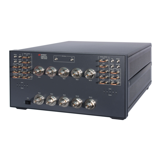
U3022AH10 Description Description The Keysight U3022AH10 is a 10-Port Multiport Test Set Extension designed to be configured for high power measurements in either a 12 or 14 port network analyzer measurement system. The Keysight U3022AH10 has the following key features: •... -
Page 11: Network Analyzer Requirements
N5242-20206 RF Locking Link, Opt 129 (right) N5242-20207 Rear Locking Link, Opt 129 (left) N3022-20238 RF cable, semi-rigid, ECal jumper U3022AH10 Option 042 Accessories (Purchased Separately) 0515-2317 Screw, metric (T15, M3.5, 12 mm long) 5023-0132 Locking feet, rear N5242-20138 Rear Locking Link (right) -
Page 12: Definitions
* New dark color version (Keysight Palette 2015) Network Analyzer Interface Kit Options The U3022AH10 requires the following kit to interface the test set with your analyzer. The interface kit model option includes the hardware Lock-Link and cable kit listed in... -
Page 13: General Specifications
PNA-X that is used with the Test Set and components used for high power configurations. A functional certificate is supplied for the U3022AH10. The U3022AH10 performance is based on external components such as the calibration kit and network analyzer. There are no internal adjustment in the U3022AH10, therefore an annual calibration is not required. -
Page 14: Environmental Requirements
11.4 kg 19.1 cm 42.5 cm 42.6 cm (25 lb) (7.5 in) (16.7 in) (17.0 in) U3022AH10 14.4 kg 22.9 cm 42.5 cm 50.8 cm Option 129 (31.7 lb) (9.0 in) (16.7 in) (20.0 in) U3022AH10 User's and Service Guide... -
Page 15: Frequency Range And Maximum Power Levels
General Specifications Frequency Range and Maximum Power Levels The U3022AH10 frequency range is 10 MHz to 26.5 GHz. It is recommend that you do not operate near damage levels. The power levels must be 3 dB below maximum level to ensure no damage. See... - Page 16 10 GHz to 15 GHz −8.5 dB 15 GHz to 20 GHz −10.0 dB 20 GHz to 26.5 GHz −15 dB Reflection Tracking takes into account Source Loss, Receiver Loss, Margin, and PNA-X Mixer Cal. U3022AH10 User's and Service Guide...
-
Page 17: Front And Rear Panel Features
— CPLR THRU - SRC OUT, Jumper can be removed to install the amplifiers and isolators. • Ports 3 - 12 — SRC OUT - CPLR THRU, Jumper can be removed to install the amplifiers and isolators. • Option 129 Port — NOISE SOURCE PORTS, In and OUT (SMA female). U3022AH10 User's and Service Guide... -
Page 18: Test Ports - 3.5 Mm Bulkhead (Male)
• The LED is Off (not illuminated) when the Test Set power switch is in Standby, or not addressed by a PNA-X. Standby Switch Note that this switch is Standby only, not a line switch. To disconnect the mains from the instrument, remove the power cord. U3022AH10 User's and Service Guide... -
Page 19: Control Lines And Voltage Adjust
Connection to another Test Set. Line Module The line fuse, as well as a spare, reside within the line module. Figure 6 on page 20 illustrates where the fuses are located and how to access them. U3022AH10 User's and Service Guide... -
Page 20: Available Fuses
For continued protection against fire hazard replace line fuse only with same type and rating. The use of other fuses or material is prohibited. Figure 6 Line Fuse Verify that the premise electrical voltage supply is within the range specified on the instrument. U3022AH10 User's and Service Guide... -
Page 21: System Configurations
U3022AH10 System Configurations System Configurations The Keysight U3022AH10 High Power Test Set can be configured for many applications. Included in this document are four typical configurations: "System Setup, 12/14 Port RF Cable Interface Configuration" on page 25. • Figure 44, “1 Watt High Power Configuration” on page 66. -
Page 22: System Setup N5242A Pna-X
3. Install the two rear locking feet (5023-0132) using the included screws (0515-1619), where the standoffs were removed. Refer to Figure Figure 8 Install Locking Feet Locking Feet Screws (0515-1619) (5023-0132) Included in package U3022AH10 User's and Service Guide... - Page 23 U3022AH10 System Configurations 4. Install the two rear locking feet onto the U3022AH10. Looking at the front panel, the N5242-20138 (for Std) or N5242-20206 (for Opt 129) is the right foot and the N5242-20139 (for Std) or N5242-20207 (for Opt 129) is the left foot. Two screws (0515-2317) are included with these rear feet.
- Page 24 • PNA − 5023-0132 (Kit includes locking feet and screws) • Test Set (STD) − N5242-20138 and N5242-20139 are the rear lock feet • Test Set (Opt 129) - N5242-20206 and N5242-20207 are the rear lock feet (provided) • Screw − 0515-2317 U3022AH10 User's and Service Guide...
-
Page 25: System Setup, 12/14 Port Rf Cable Configuration
• Port 13 over Port 3 (U3022-80002) • Port 14 over Port 4 (U3022-80003) 5. Connect the cable (N4011-21002) from the PNA-X Test Set I/O to the U3022AH10 Test Set I/O on the rear panel. See Figure 13 on page 6. - Page 26 System Setup, 12/14 Port RF Cable Interface Configuration 91 92 92 91 93 94 94 93 91 92 92 91 93 94 94 93 Figure 13 Rear Panel I/O Cable Configuration (Opt 129 Rear View) U3022AH10 User's and Service Guide...
-
Page 27: System Operational Checks
Before beginning this procedure complete the following steps: • Stack the analyzer system for the 12/14-Port System. • Install the Test Set I/O cable on the U3022AH10 and PNA-X rear panels. • Install all of the RF interface cables as shown in Figure •... - Page 28 System Configurations U3022AH10 Figure 14 Typical Reflection Response Port 1 and 2 Figure 15 Port 1 and 2, RF Path Diagram U3022AH10 User's and Service Guide...
- Page 29 System Configurations U3022AH10 Figure 16 Typical Reflection Response Test Set (Odd Ports) Figure 17 Typical Reflection Response Test Set (Even Ports) U3022AH10 User's and Service Guide...
- Page 30 System Configurations U3022AH10 Figure 18 Test Set RF Path Diagram U3022AH10 User's and Service Guide...
-
Page 31: Controlling The System With N5242A/B
Controlling the System with N5242A/B Controlling the System with N5242A/B This section will describe how to setup and operate the U3022AH10 Multiport Test Set with the N5242A/B 2-Port or 4-Port PNA-X Network Analyzer. The U3022AH10 Multiport Test Set is considered a “slave” instrument. The N5242A/B must be used to control the Test Set. -
Page 32: 12/14 Port System With N5242A/B
Figure 19 Multiport Configuration Select U3022AE10 or U3022AH10 (Opt 129) from the Test Set drop-down menu and select Restart as a multiport PNA with this testset. Press OK. The PNA-X will restart the network application with the U3022AH10 Multiport Test Set interface features. -
Page 33: External Test Set Control Feature
Controlling the System with N5242A/B External Test Set Control Feature To verify that the network application has the U3022AH10 interface features, select Channel > External Test Set > Other -OR- (Instrument > Setup > External Hardware > External Device... > Multiport > Other Test Set Setup...). - Page 34 The following menu will allow the physical Ports 1 through 12 to be identified as any port for your convenience. For example, Port 5 can be named Port 2. The External Test Set Control - U3022AH10 also allows control of the DUT control lines, refer to “DUT Control Lines”...
-
Page 35: Trace Measure S-Parameter
The front panel R LED indicates the port is the Receiver and the S LED indicates the port is the Source. The 'B' Model analyzer S-Parameter selections are done by using the front keypad. For example, to select S25: MEAS [MEAS] > Enter S-Parameter > [2][.][5] [Enter] Figure 25 12-Port Trace Measure U3022AH10 User's and Service Guide... -
Page 36: New Trace Measure S-Parameter
Multiple S-Parameters can be made from the New Measurement menu. In the drop-down menu select Trace > New Trace -OR- (Instrument > Trace > New Trace). Figure 26 Selecting PNA-X New Trace Measure Figure 27 New Trace Selection U3022AH10 User's and Service Guide... -
Page 37: Balanced Tab
In the search menu type in “Multiport and Balanced.” Figure 28 Balanced Receiver Tab: The S-Parameter measurements can be ratioed with selectable Denominators for each port and receiver. Refer to the standard PNA-X documentation for more information. Figure 29 Receiver Ports U3022AH10 User's and Service Guide... -
Page 38: Rf Path Configuration Check For Analyzers With Option 029
Utilities System> Configure > Preferences -OR- (Utility > System > System Setup > Preferences > User Preset). If not, select Meas: Port 1 Noise Tuner Switch is set to external. Figure 30 RF Path Configuration U3022AH10 User's and Service Guide... -
Page 39: Sweep Setup For Multiport And Standalone Pna-X Modes
1. Select [Sweep] > Sweep Setup > Timing. 2. Select Timing tab. 3. Select Sweep Mode: Stepped. 4. Deselect Time: Auto Sweep Time. 5. Set Dwell Time > Apply > OK. Figure 32 Sweep Setup, N52xxB U3022AH10 User's and Service Guide... -
Page 40: N-Port Calibration With N5242A/B
3. Connect the ECal or the mechanical cal kit to the ports you are calibrating following the Cal Wizard prompts and press Measure after each connection. 4. At the Calibration Completed prompt, select Save As User Calset and type the name desired. Press Save. U3022AH10 User's and Service Guide... -
Page 41: Interface Control Mode
• Control data is sent in the following order and this order cannot be changed: Refer to the PNA Help menu. 1. GPIB Commands - BEFORE 2. Handler I/O Control 3. Test Set I/O Control (addr.data) 4. Dwell After Command 5. Aux I/O Output Voltage U3022AH10 User's and Service Guide... -
Page 42: How To Access Interface Control Settings
Please review this application before connecting the test set to the PNA. Information regarding this application can be found in the PNA Help menu, Interface Control. The application is shown in Figure 34 below. Figure 34 Interface Control Application U3022AH10 User's and Service Guide... -
Page 43: Using Interface Control Mode
The front panel Enter key can be used to insert a new line into the field. The quantity of test set I/O entries that can be entered is limited by the available memory of the analyzer. Address and Data example: addr.data (3) 16.1 32.2 U3022AH10 User's and Service Guide... - Page 44 Word Pad. Applies the settings and closes the dialog box. Cancel: Does not apply changes that were made and closes the dialog box. Help: Provides additional information for using the interface control application. U3022AH10 User's and Service Guide...
-
Page 45: Scpi Control Mode
Utility > System > Configure > SICL/GPIB/SCPI -OR- (System Setup > Remote Interface > SCPI Monitor Input > Show SCPI Parser Console), and check SCPI Command Processor Console box. Figure 36 Command Console for 'A' Model Analyzers U3022AH10 User's and Service Guide... -
Page 46: Scpi Command Processor Console
Address and data are separated by a comma. Commands should be separated by a new line, or carriage return. For example: CONT:EXT:TEST:DATA <address>,<data> CONT:EXT:TEST:DATA 0,0 Example: CONT:EXT:TEST:DATA 0,0 Figure 38 SCPI Command Processor Refer to “Address and Data Values” on page U3022AH10 User's and Service Guide... -
Page 47: Option 129 External Source Path
U3022AH10 Option 129 External Source Path The U3022AH10 with Option 129 allows an external ECal module, or noise source, to be switched into the Source path of Ports 1, 3, 5, 9, or 11. Only one port can be the active source. The front panel EXT NOISE SOURCE IN is... - Page 48 Noise Source Port 5 0.11 Noise Source Port 7 0.12 Noise Source Port 9 0.13 Noise Source Port 11 An 8 is added to the Data Value to activate the Option 129 switch, as indicated in Table U3022AH10 User's and Service Guide...
-
Page 49: Address And Data Values
Source Port 3 = address 0, data 1, and Receiver Port 7 = address 0, data 48. The data values are added together, for an entry of 0.49. For more information, refer to the PNA-X Help menu. U3022AH10 User's and Service Guide... - Page 50 U3022AH10 Address and Data Values Example 1 U3022AH10 Option 129 Block Diagram Figure 40 U3022AH10 User's and Service Guide...
- Page 51 U3022AH10 Address and Data Values Example 2 U3022AH10 Option 129 Block Diagram Figure 41 S-Parameter measurements are not possible in this example. U3022AH10 User's and Service Guide...
- Page 52 U3022AH10 Address and Data Values Example 2b U3022AH10 STD Block Diagram Figure 42 S-Parameter measurements are not possible in this example. U3022AH10 User's and Service Guide...
- Page 53 Selects Noise Source IN and OUT paths and Receiver for Port 9 (S99) Selects Noise Source IN and OUT paths and Receiver for Port 11 (S1111) Refer to "System Block Diagrams" starting on page 72 for in-depth RF path information. U3022AH10 User's and Service Guide...
-
Page 54: Dut Control Lines
To select a Test Set DUT control line configuration, all 8 DUT control lines must be set. To do this you must add AD7 to AD0 binary number and convert this to a decimal equivalent. U3022AH10 User's and Service Guide... - Page 55 Input a signal that is outputted when each line is low from the external DC power supply. Able to output 0 V as low from the each line by connecting to pin 15. ground terminal U3022AH10 User's and Service Guide...
-
Page 56: Setting The Variable Source Voltage
DUT and the U3022AH10 without an external DC power supply. Connect pin 12 to pin 13 for +5 V, and pin 14 to pin 15 to provide the ground path. Connect each DUT control line to the external device under test. -
Page 57: Using An External Power Supply
Using an External Power Supply Figure 45 below illustrates an example of the connection between the DUT and the U3022AH10 with an external DC power supply. Input the High and Low signals from the external power supply to the Positive Input and Negative Input respectively, and connect each line to the control terminal of the DUT. - Page 58 0 to +5 V Negative Input –5 to 0 V Maximum Current 100 mA (in total of each line) Impedance < 10 Ω Range of Variable Voltage +2 to +5 V Figure 46 Block Diagram of DUT Control U3022AH10 User's and Service Guide...
-
Page 59: High Power Measurements
When using high power configurations an attenuator must be placed in the receiver path, and the couplers and isolators must be installed in the source path or damage to the PNA-X, or the U3022AH10 Test Set will occur. Refer to “Frequency Range and Maximum Power Levels” on page Getting Started A power meter is required for the following procedure. -
Page 60: Measuring Booster Amplifier Gain
Table Figure 47, and Figure 6. Turn On the PNA-X and U3022AH10 Test Set. 7. Select multiport mode. Refer to “Controlling the System with N5242A/B” page 8. Select trace S11 if you are using Port 1 or Odd Ports SRC Out. If you are using another port as the source port, set Sxx to the port desired. - Page 61 A IN Port 3 SOURCE OUT CPLR THRU Odd Ports RCVR IN RCVR OUT SRC IN SRC OUT Port 1 CPLR THRU SRC OUT Coupler Booster Amplifier Coupler Coupler Main Output 20 dB INPUT OUTPUT U3022AH10 User's and Service Guide...
- Page 62 CPLR THRU SRC OUT Coupler Booster Amplifier 20 dB Coupler Coupler Main Input Output Output Figure 50 Measuring the Booster Amplifier Gain Power Meter Coupler 20 dB Coupler Coupler Main Output Booster Amplifier OUTPUT INPUT U3022AH10 User's and Service Guide...
-
Page 63: Setting The Power Level At The Output Of The Dut
Save this state to recall the power level for the Input power level to the DUT. The power level should not be above the level that was determined in step 13 page U3022AH10 User's and Service Guide... - Page 64 RCVR REF IN). 7. Turn Off the booster amplifier and connect the external coupler ARM to the REF INPUT (RCVR R1 IN or RCVR R2 IN). Refer to Figure 51 Figure 52 page U3022AH10 User's and Service Guide...
- Page 65 RCVR A/B IN). 16. Connect the attenuator outputs to receiver A IN and B IN. If you are using Ports 13 or 14, connect the same value attenuators from RCVR OUT to RCVR C/D IN. U3022AH10 User's and Service Guide...
- Page 66 Booster Amplifier OUTPUT INPUT Isolator Figure 52 20 Watt High Power Configuration REF Attenuator Coupler 20 dB RCVR A Attenuator Coupler Coupler Main Output RCVR A Attenuator Fix Attenuator Fix Attenuator Booster Amplifier OUTPUT INPUT U3022AH10 User's and Service Guide...
-
Page 67: Calibrating The System And Measuring The Dut
The isolators placement is important to ensure that the signal is attenuated into the U3022AH10 SRC OUT isolator connections for Port 1 and Port 2. The reverse attenuation or isolation factor of the isolator should be 20 dB or greater. -
Page 68: Service Information
Refer to “Contacting Keysight” on page There are many other repair and calibration options available from the Keysight Technologies support organization. These options cover a range of service agreements with varying response times. Contact Keysight for additional information on available service agreements for this product. - Page 69 U3022AH10 Service Information Figure 53 Top View DUT Co ntrol Bd Test Set Control Bd Switch Interface Bd (bottom Bd) (top Bd) Option 129 Switch Couplers (x10) U3022AH10 User's and Service Guide...
- Page 70 U3022AH10 Service Information Figure 54 Bottom View Power Supply Line Module Fuses (x2) Option 129 Switch Couplers (x10) U3022AH10 User's and Service Guide...
-
Page 71: Theory Of Operation
U3022AH10 Theory of Operation Theory of Operation The following is a description of the operation of the U3022AH10. Reference the U3022AH10 block diagrams shown, beginning with Figure 55 on page 72. This section assumes the user has a general understanding of couplers, switches, and network analyzers. -
Page 72: System Block Diagrams
SOURCE OUT CPLR THRU SOURCE OUT SOURCE OUT CPLR THRU CPLR THRU CPLR THRU SOURCE OUT SOURCE OUT CPLR THRU SRC OUT SRC IN SOURCE OUT CPLR ARM CPLR THRU B IN B IN CPLR ARM U3022AH10 User's and Service Guide... - Page 73 CPLR ARM SRC IN SRC OUT SOURCE OUT CPLR THRU CPLR THRU SOURCE OUT SOURCE OUT CPLR THRU CPLR THRU SOURCE OUT SRC OUT SRC IN CPLR ARM B IN RCVR IN RCVR OUT REF ATTN U3022AH10 User's and Service Guide...
- Page 74 A IN CPLR ARM SRC IN SRC OUT SOURCE OUT CPLR THRU CPLR THRU SOURCE OUT SOURCE OUT CPLR THRU CPLR THRU SOURCE OUT SRC OUT SRC IN CPLR ARM B IN RCVR IN RCVR OUT U3022AH10 User's and Service Guide...
- Page 75 U3022AH10 Theory of Operation Figure 58 14-Port System, Option 129 Test Set U3022AH10 User's and Service Guide...
-
Page 76: Troubleshooting The Test Set
Troubleshooting the Test Set Troubleshooting the Test Set If the U3022AH10 is not operating properly, use the following procedures to isolate and repair the type of failure encountered. It is recommended that a qualified service technician perform the following procedures. -
Page 77: Non-Rf Malfunctions
Verify that the DC power indicator LEDs are ON. Refer to Figure 60, page Note: The LED indicators only indicate the presence of a DC voltage, not the DC voltage level. Use the indicated wire locations for voltage measurements. TP1 is your common. U3022AH10 User's and Service Guide... -
Page 78: Rf Switching Malfunctions
+21 Vdc voltage from the switch driver board. 1. The PNA and the Test Set need to be connected together with the Test Set I/O cable (N4011-21002). 2. Verify the Test Set I/O cable is installed correctly. See Figure 13 on page U3022AH10 User's and Service Guide... -
Page 79: Source And Receiver Path Test
• Set the PNA to Interface Control Mode with front panel keys: Trace/Chan > Channel > Hardware Setup > Interface Control -OR- (Instrument > Setup > Internal Hardware > Interface Control...). In the drop-down window, select the Enable Interface Control box. U3022AH10 User's and Service Guide... - Page 80 A/B IN to CPLR ARM Receiver Figure 63 The <addrs>.<data> values shown in the following test instructions are for the new Option 129 Test Set. Refer to Table 11 page 62 for values used for the standard model. U3022AH10 User's and Service Guide...
-
Page 81: Source Signal Path Insertion Loss Test
Source OUT to Port 12 P12 CPLR, S20 16.5 (16.117) 1. Use the Source IN port associated with this group of test ports. 2. Standard model source control codes. Figure 61 Source OUT to Ports 3-12 Path Response U3022AH10 User's and Service Guide... -
Page 82: Receiver Signal Path Insertion Loss Test
16.64 P10 CPLR, S21 B IN to Port 12 P12 CPLR, S21 16.80 Use the Source IN port associated with this group of test ports. Figure 62 RCVR A/B IN to Ports 3-12 Path Response U3022AH10 User's and Service Guide... - Page 83 Path Components (Typical) Group <address>.<data> Odd Ports A IN to CPLR ARM Figure 63 Even Ports B IN to CPLR ARM 16.0 1. Use the Source IN port associated with this group of test ports. U3022AH10 User's and Service Guide...
-
Page 84: Safety And Regulatory Information
Declaration of Conformity A copy of the Declaration of Conformity is available upon request, or a copy is available on the Keysight Technologies web site at http://regulations.about.keysight.com/DoC/ Statement of Compliance This product has been designed and tested in accordance with accepted industry standards, and has been supplied in a safe condition. - Page 85 4 °C for every 100 watts dissipated in the cabinet. If the total power dissipated in the cabinet is greater than 800 watts, then forced convection must be used. U3022AH10 User's and Service Guide...
-
Page 86: Servicing
LINE switch (disconnecting device). To prevent electrical shock, disconnect the Keysight Technologies U3022AH10 from mains electrical supply before cleaning. Use a dry cloth or one slightly dampened with water to clean the external case parts. Do not attempt to clean internally. -
Page 87: Electrostatic Discharge Protection
2. While wearing a grounded wrist strap, grasp the outer shell of the cable connector. 3. Connect the other end of the cable to the test port and remove the short from the cable. Figure 64 ESD Protection Setup U3022AH10 User's and Service Guide... -
Page 88: Instrument Markings
Forty years is the expected useful life of the product. This symbol on all primary and secondary packaging indicates compliance to China standard GB 18455-2001. South Korean Certification (KC) mark; includes the marking's identifier code which follows the format: MSIP-REM-YYY-ZZZZZZZZZZZZZZ. U3022AH10 User's and Service Guide... -
Page 89: Battery
Safety and Regulatory Information U3022AH10 Battery: Do not throw batteries away but collect as small chemical waste, or in accordance with your country’s requirements. You may return the battery to Keysight Technologies for disposal. Refer to “Contacting Keysight” on page 90 for assistance. -
Page 90: Keysight Support, Services, And Assistance
Keysight for repair. If you wish to send your instrument to Keysight Technologies for service or repair: — To improve turn-around time, return your test set along with your network analyzer and cables to Keysight so that we may verify the operation of the complete system. - Page 91 U3022AH10 User's and Service Guide...
- Page 92 This information is subject to change without notice. © Keysight Technologies 2011, 2018, 2019 Edition 4: March 2019 Supersedes: June 2018 www.keysight.com...
Need help?
Do you have a question about the U3022AH10 and is the answer not in the manual?
Questions and answers