Table of Contents
Advertisement
Quick Links
Keysight Technologies
U3022AM06
Multiport Test Set
Notice: This document contains references to
Agilent Technologies. Agilent's former Test and
Measurement business has become Keysight
Technologies. For more information, go to
www.keysight.com.
Use this manual with the following documents:
PNA Series Network Analyzer On-Line Help
System
User's and
Service Guide
Advertisement
Table of Contents

Related Manuals for Keysight Technologies U3022AM06


Summary of Contents for Keysight Technologies U3022AM06
- Page 1 Keysight Technologies U3022AM06 Multiport Test Set Notice: This document contains references to Agilent Technologies. Agilent's former Test and Measurement business has become Keysight Technologies. For more information, go to www.keysight.com. Use this manual with the following documents: PNA Series Network Analyzer On-Line Help...
- Page 2 THESE TERMS, THE WARRANTY Keysight shall be under no obligation TERMS IN THE SEPARATE to update, revise or otherwise modify © Keysight Technologies, Inc. 2009, AGREEMENT WILL CONTROL. the Software. With respect to any 2019 technical data as defined by FAR Technology Licenses 2.101, pursuant to FAR 12.211 and...
-
Page 3: Table Of Contents
Table of Contents U3022AM06 Introduction Description Verifying the Shipment Network Analyzer Requirements Measurement Application Notes Available Options Test Set Options Accessory Options Network Analyzer Interface Kit Options General Specifications Power Requirements Environmental Requirements Equipment Heating and Cooling Required Conditions for Accuracy Enhanced Measurement... - Page 4 Table of Contents New Trace Measure S-Parameter Balanced Tab RF Path Configuration with Option 029 N- Port Calibration Interface Control Mode Overview of the Interface Control How to Access Interface Control Mode Using Interface Control Mode SCPI Control Mode Overview of the SCPI Control How to Access the Command Processor SCPI Command Processor Console Address and Data Values...
- Page 5 Table of Contents Troubleshooting the Test Set Non-RF Failures RF Switching Failures RF Switching Path Test Equipment Required Equipment Setup Source and Receiver Path Tests Wiring Diagram and Internal Views Safety and Regulatory Information Introduction Safety Earth Ground Statement of Compliance Before Applying Power Servicing Connector Care and Cleaning Precautions...
- Page 6 Table of Contents...
- Page 7 U3022AM06 Keysight U3022AM06 User's and Service Guide...
-
Page 8: U3022Am06 Introduction
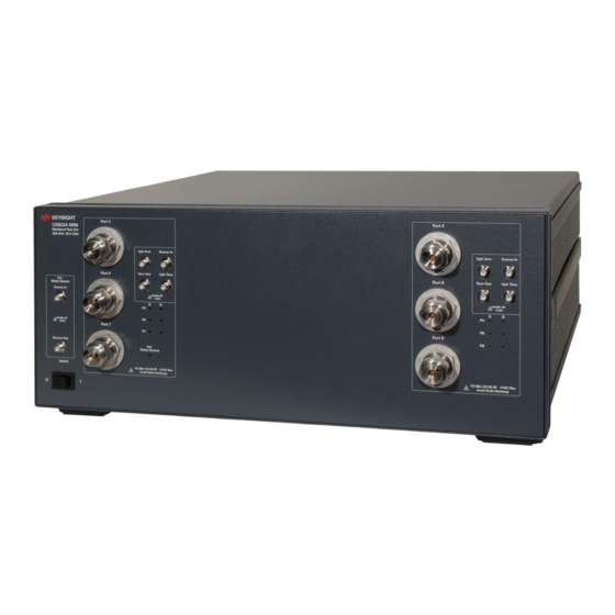
U3022AM06 Introduction Introd uction This document describes how to use and service the U3022AM06 Multiport Test Set. Figure 1 U3022AM06 Test Set Keysight U3022AM06 User's and Service Guide... - Page 9 U3022AM06 Introduction Figure 2 N5230A 4-Port PNA-L with U3022AM06 Figure 3 E8362B 2-Port PNA with U3022AM06 Keysight U3022AM06 User's and Service Guide...
- Page 10 U3022AM06 Introduction Figure 4 N5222A/B or N5242A/B 2-Port PNA-X with U3022AM06 Figure 5 N5222A/B or N5242A/B 4-Port PNA-X with U3022AM06 Keysight U3022AM06 User's and Service Guide...
-
Page 11: Description
The Keysight PNA and PNA-X Network Analyzers will be referred to throughout this document as the PNA and PNA-X. The U3022AM06 will be referred to as the Test Set. Verifying the Shipment To verify the contents shipped with your product, refer to the “Box Content List”... -
Page 12: Network Analyzer Requirements
Ensure that the network analyzer has the latest version of firmware installed. The following web site links will provide the necessary information needed: • Documentation - http://na.support.keysight.com/pna/documents.html (PNA) http://na.support.keysight.com/multiport.html (Test Set) • U3022AM06 Test Set File - http://na.support.keysight.com/multiport/testsetsupport.html • Network Analyzer Firmware - http://na.support.keysight.com/pna/firmware/firmware.html Keysight U3022AM06 User's and Service Guide... -
Page 13: Measurement Application Notes
Accessory Options Front handle and rack flange accessories: • Option 1CM - Rack-Mount without Handles Kit (1CM114A) • Option 1CN - Front Handle Kit (1CN103A) • Option 1CP - Rack-Mount with Front Handle Kit (1CP106A) Keysight U3022AM06 User's and Service Guide... -
Page 14: Network Analyzer Interface Kit Options
U3022AM06 Available Options Network Analyzer Interface Kit Options The U3022AM06 requires one of the following kits to interface the Test Set with your Analyzer. The interface kit model option includes the hard ware lock-link and cable kit listed in Table... -
Page 15: General Specifications
Test Set to the Analyzer. • U3022AM06 maximum power is 350 W. This is a Safety Class I prod uct (provided with a protective earthing ground incorporated in the power cord). The mains plug shall only be inserted into a socket outlet provided with a protective earth contact. -
Page 16: Environmental Requirements
Test Set. Table 4 Instrument Dimensions Model Weight Height Width Depth 19.1 cm 42.5 cm 43.2 cm U3022AM06 11.4 kg (25 lb) (7.5 in) (16.7 in) (17 in) Keysight U3022AM06 User's and Service Guide... -
Page 17: Frequency Range And Power Levels
(+30 dBm, 7 Vdc). The power levels must be 3 dB below maximum level to ensure no damage. Table 6 Recommended Maximum Power Levels and Vrms U3022AM06 Test Port RF Power Levels PORT 3-8 +27 dBm 5 Vdc U3022AM06 Access Ports: SOURCE OUT +20 dBm 2.2 Vdc... -
Page 18: Typical Reflection Tracking
500 MHz to 3.2 GHz −3 3.2 GHz to 10 GHz −5 10 GHz to 16 GHz −7 16 GHz to 20 GHz −10 20 GHz to 24 GHz −11 24 GHz to 26.5 GHz −12 Keysight U3022AM06 User's and Service Guide... -
Page 19: Front And Rear Panel Features
Active LED The Active LED is on when the Test Set is connected and addressed by a Analyzer. The LED is off when the Test Set is in Standby, or not addressed by the Analyzer. Keysight U3022AM06 User's and Service Guide... - Page 20 Requires an English 1/4-20 thread nut (2950-0004) and lock washer (2190-0067). Pass Through Connection to another Test Set. Interface Test Set Interface The Test Set Interface connector is used to send address and data to the Test Set from the Analyzer. Keysight U3022AM06 User's and Service Guide...
- Page 21 For continued protection against fire hazard replace line fuse only with same type and rating. The use of other fuses or material is prohibited. Figure 8 Line Module and Fuse Verify that the premise electrical voltage supply is within the range specified on the instrument. Keysight U3022AM06 User's and Service Guide...
-
Page 22: Installation Procedures, Test Set To Analyzer
2. Remove the feet from the bottom of the Analyzer. 3. Remove the 2 lower standoffs from the rear panel on the Analyzer using a T20 Torx driver. Figure 9 Rear Bottom Feet Standoffs (x2) Feet (x4) Keysight U3022AM06 User's and Service Guide... - Page 23 5. Remove the two upper standoffs from the rear panel on the Test Set. 6. Install the left and right lock-links onto the Test Set. Figure 11 Install Rear Lock-links to the Test Set Right lock-link Left lock-link 5022-2816 5022-2818 Screw 0515-1244 (x2) T20 M3.5X0.6 12 mm Keysight U3022AM06 User's and Service Guide...
- Page 24 If the Analyzer's lock-links are not aligned with the screw holes, loosen the screws securing the lock-links to the instrument slightly to align and tighten. Figure 13 Lock-Link Screws Refer to “Network Analyzer Interface Kit Options” on page 14 Keysight U3022AM06 User's and Service Guide...
-
Page 25: Hardware Lock-Link Installation (U3021-60002)
2. Remove the feet from the bottom of the Analyzer. 3. Remove the 2 lower standoffs from the rear panel on the Analyzer using a T20 Torx driver. Figure 14 Rear Bottom Feet Standoffs (x2) Feet (x4) Keysight U3022AM06 User's and Service Guide... - Page 26 5. Remove the top two standoffs from the rear panel on the Test Set. 6. Install the left and right lock-links onto the Test Set. Figure 16 Install Lock-link on Test Set Right lock-link Left lock-link N5242-20138 N5242-20139 Screw 0515-2317 (x2) T15 M3.5X0.6 12 mm Keysight U3022AM06 User's and Service Guide...
- Page 27 8. Secure the Analyzer’s lower lock-links to the Test Set’s upper lock-link, using the spring–loaded screws. If the Analyzer's lock-link are not aligned with the screw holes, loosen the screws securing the lock-link to the instrument slightly to align and tighten. Figure 18 Lock-Link Screws Keysight U3022AM06 User's and Service Guide...
-
Page 28: Hardware Lock-Link Installation (U3021-60003)
N5245-20131 - Left Lock-link, Test Set 2. Remove the feet from the bottom of the Analyzer. 3. Remove the 2 lower standoffs from the rear panel on the Analyzer. Figure 19 Rear Bottom Feet Standoffs (x2) Feet (x4) Keysight U3022AM06 User's and Service Guide... - Page 29 N5242-20130 is the right foot and the N5242-20131 is the left foot. Two screws (0515-2317) are included with this option. Figure 21 Install Lock-link on Test Set Right lock-link Left lock-link N5242-20130 N5242-20131 Screw 0515-2317 (x2) T15 M3.5X0.6 12 mm Keysight U3022AM06 User's and Service Guide...
- Page 30 8. Secure the Analyzer’s lower lock-links to the Test Set’s upper lock-link, using the spring–loaded screws. If the Analyzer's lock-link are not aligned with the screw holes, loosen the screws securing the lock-link to the instrument slightly to align and tighten. Figure 23 Lock-Link Screws Keysight U3022AM06 User's and Service Guide...
-
Page 31: Rf Interface Cable Connections (U3021-60045)
Table 9 10-Port Interface Cable Connection (U3021-60045) RF Cables From: PNA-L To: Test Set Z5623-20418 SOURCE OUT SOURCE OUT Z5623-20418 CPLR ARM CPLR ARM Z5623-20419 CPLR THRU CPLR THRU Z5623-20419 RCVR IN RCVR OUT Keysight U3022AM06 User's and Service Guide... - Page 32 Port 2 over Port 4 (U3022-80004) • Port 9 over Port 2 (U3022-80006) • Port 10 over Port 3 (U3022-80007) Refer to “System Operational Checks” on page 40 for turn-on verification of the multiport system. Keysight U3022AM06 User's and Service Guide...
-
Page 33: Rf Interface Cable Connections (U3021-60043)
Each end of the interconnect RF cables have a different length from the bend. When connecting the RF Interconnect cables be sure that the longer end (from the bend) is connected to the Analyzer. Keysight U3022AM06 User's and Service Guide... - Page 34 Figure 25 illustrates the final two digits of the part number for each cable. The cables must be connected in the numeric order listed in Table Figure 25 8-Port Interface Connections 19 17 23 21 Keysight U3022AM06 User's and Service Guide...
-
Page 35: Rf Interface Cable Connection (U3021-60046 Or U3021-60047)
Analyzer's port numbers. • Port 9 over Port 3 (U3022-80006) • Port 10 over Port 4 (U3022-80008) Over torque will cause damage to the Test Set and may cause connectors to spin or become loose. Keysight U3022AM06 User's and Service Guide... - Page 36 Kit U3021-60047 contains eight extra cables that are not listed above and are not used in this interface connection Figure 26 N5242A/B RF Interface Cable Connections 29 30 Port 9 Port 10 42 41 30 32 42 44 Keysight U3022AM06 User's and Service Guide...
-
Page 37: Rf Interface Cable Connection (U3021-60050)
Analyzer's port numbers. • Port 9 over Port 3 (U3022-80006) • Port 10 over Port 4 (U3022-80008) Over torque will cause damage to the Test Set and may cause connectors to spin or become loose. Keysight U3022AM06 User's and Service Guide... - Page 38 Apply the Port 9 and 10 labels over Ports 3 and 4 on the PNA-X. Figure 27 N5247A/B RF Interface Cable Connections 162 163 161 Label Label 167 166 Port 9 Port 10 163 161 167 165 Keysight U3022AM06 User's and Service Guide...
-
Page 39: Test Set I/O Cable Installation
Perform the “System Operational Checks” on page If the problem still exists, perform the “RF Switching Failures” on page If a power hole or other failure still exist, refer to “Contacting Keysight” on page 100. Keysight U3022AM06 User's and Service Guide... -
Page 40: System Operational Checks
Figure 32 to 34 on pages 42 to 43 The trace ripple (peak-peak variation) will be higher than when using an ECal Module due to variation in your Short’s performance. If response is in question perform “Cal Kit Operational Check” on page Keysight U3022AM06 User's and Service Guide... - Page 41 U3022AM06 System Operational Checks Figure 29 Typical Reflection Response Ports 1-2 Figure 30 Reflection Response Signal Path Diagram Ports 1-2 Keysight U3022AM06 User's and Service Guide...
- Page 42 U3022AM06 System Operational Checks Figure 31 Typical Reflection Response Ports 3-8 Figure 32 Reflection Response Signal Path Diagram Ports 3-8 Keysight U3022AM06 User's and Service Guide...
- Page 43 U3022AM06 System Operational Checks Figure 33 Reflection Response Signal Path Diagram Ports 5-6 Figure 34 Reflection Response Signal Path Diagram Ports 7- 8 Keysight U3022AM06 User's and Service Guide...
-
Page 44: Controlling The Test Set
20 to 30 °C temperature range. Nominal performance is not warranted. • Typical describes characteristic performance, which 80% of instruments are expected to meet when operated over a 20 to 30 °C temperature range. Typical performance is not warranted. Keysight U3022AM06 User's and Service Guide... -
Page 45: Multiport Mode (Option 551)
Utility > System > Configure > Multiport Capability - OR - (Instrument > Setup > External Hardware > Multiport > Multiport Configuration...). 2. Select U3022AM06 (8 or 10-Port System) from the drop-down menu and select Restart as a multiport PNA with this testset > OK. The Analyzer will restart the network application with the Test Set interface features. -
Page 46: External Test Set Control Feature
This menu will allow the physical Ports 1 thru 10 to be identified as any port for your convenience. For example; Port 5 can be named Port 2. The External Test Set Control-U3022AM06 also allows control of the DUT control lines, refer to “Control Lines”... -
Page 47: Trace Measure S-Parameter
Trace/Chan > Trace > New Trace. - OR- (Instrument > Trace > New Trace). The dialog box allows the selection of any of the 100 S-Parameters. Refer to Figure 39 Figure 40 on page New S-Parameter Measurement Figure 38 Keysight U3022AM06 User's and Service Guide... - Page 48 U3022AM06 Controlling the Test Set Figure 39 10-Port New Trace Measure (S11 - S55) Use the scroll bar to select other s-parameter measurements Figure 40 10-Port New Trace Measure (S66 - S1010) Keysight U3022AM06 User's and Service Guide...
-
Page 49: Balanced Tab
In the search menu type “Multiport and Balanced.” Figure 41 Selecting Balanced Measurements Receivers Tab The S-Parameter measurements can be ratioed with selectable Denominators for each port and receiver. Refer to the standard documentation for more information. Figure 42 Receiver Measurements Keysight U3022AM06 User's and Service Guide... -
Page 50: Rf Path Configuration With Option 029
2. Verify that the Port 1 Noise Tuner Switch is set to external. Select Utilities System> Configure > Preferences. If not, select Meas: Port 1 Noise Tuner Switch is set to external. Figure 43 RF Path Configuration Keysight U3022AM06 User's and Service Guide... -
Page 51: N-Port Calibration
Measurement errors can be a result of firmware algorithms. Consult with Keysight Service or firmware web page for the latest Option 551 firmware revisions and history at http://na.support.keysight.com/pna/firmware/firmware.html Figure 44 ECal Characterization and Calibration Wizard Keysight U3022AM06 User's and Service Guide... - Page 52 If measurement errors occur, ensure the newest version of firmware is installed on the analyzer. Measurement errors can be a result of firmware algorithms. Consult with Keysight Service or firmware web page for the latest Option 551 firmware revisions and history at http://na.support.keysight.com/pna/firmware/firmware.html Keysight U3022AM06 User's and Service Guide...
-
Page 53: Interface Control Mode
Control data is sent in the following order and this order cannot be changed: Refer to the Help menu. 1. GPIB Commands - BEFORE 2. Handler I/O Control 3. Test Set I/O Control (addr.data) 4. Dwell After Command 5. Aux I/O Output Voltage Keysight U3022AM06 User's and Service Guide... -
Page 54: How To Access Interface Control Mode
The analyzer includes the Interface Control application and rear panel connection. Please review this application before connecting the Test Set to the Network Analyzer. Information regarding this application can be found in the Help menu, Interface Control. Figure 47 Interface Control Keysight U3022AM06 User's and Service Guide... -
Page 55: Using Interface Control Mode
The quantity of Test Set I/O entries that can be entered is limited by the available memory of the analyzer. Address and Data example: addr.data (3) 16.1 32.2 Keysight U3022AM06 User's and Service Guide... - Page 56 Word Pad. Applies the settings and closes the dialog box. Cancel: Does not apply changes that were made and closes the dialog box. Help: Provides additional information for using the interface control application. Keysight U3022AM06 User's and Service Guide...
-
Page 57: Scpi Control Mode
(System Setup > Remote Interface > SCPI Monitor Input > Show SCPI Parser Console). 2. Check the SCPI Command Processor Console box (Figure 49 and 50). Command Console for 'A' Model Analyzers Figure 49 Keysight U3022AM06 User's and Service Guide... -
Page 58: Scpi Command Processor Console
Method 1 provides more PNA-X control capability than Method 2. The following example shows two executable commands needed to create an S-parameter measurement on your Multiport system. Method 1 - Using GPIB/SCPI Command Values Figure 51 Keysight U3022AM06 User's and Service Guide... - Page 59 Address and Data values are separated by a comma. Commands should be separated by a new line, or carriage return. For example: CONT:EXT:TEST:DATA <address>,<data> CONT:EXT:TEST:DATA 0,0 Example: CONT:EXT:TEST:DATA 0,0 Method 2 - Using Test Set Address and Data Values Figure 52 Keysight U3022AM06 User's and Service Guide...
-
Page 60: Address And Data Values
4-Port network analyzers provide Ports 9 and 10. These ports do not utilize the Test Set switch paths, therefore they do not have address data values. Refer to “System Block Diagram” on page 79 for in-depth RF path information. Keysight U3022AM06 User's and Service Guide... - Page 61 U3022AM06 Address and Data Values Figure 53 Example - Address and Data (Port 3 and 7) Keysight U3022AM06 User's and Service Guide...
-
Page 62: Option 129 External Noise Source
Address and Data Values Option 129 External Noise Source The U3022AM06 with Option 129 is only operational when the PNA-X is in standalone mode and is controlled by either Interface Control or GPIB Control mode. Option 129 allows an external noise source, ECal module, or other component to be switched into the Source path of Test Ports 1, 3, 5, or 7. - Page 63 Table 15 on previous page). As shown in Figure 54 below, we used the Interface Control Mode to send <0.57> as a command on one line. Figure 54 Example 3 - Option 129 Test Port Path Selection Keysight U3022AM06 User's and Service Guide...
-
Page 64: Control Lines
100 mA (each line) Control Line DC resistance < 10 Ω (each line) Voltage Range: Positive Input 0 to +5 V Negative Input –5 to 0 V Internal Variable Voltage +2 to +5 V Keysight U3022AM06 User's and Service Guide... - Page 65 Internal voltage output, adjusted with the trimmer on the rear +2 V to +5 V panel. Positive Input Connection for internal (pin 12) or external positive voltage supply. Negative Input Connection for ground (pin 15) or external negative voltage supply. ground terminal Keysight U3022AM06 User's and Service Guide...
-
Page 66: Internal Voltage Supply Configuration
You may only connect pin 12–13, and pin 14–15, damage may result if any other paths are short-circuited. Figure 56 Internal DC Power Configuration (rear panel view) Line 1 Line 2 (Rear Panel View) TO DUT (Only required Lines) Line 8 2 to 5 Vdc TEST SET Keysight U3022AM06 User's and Service Guide... -
Page 67: External Voltage Supply Configuration
Test Set to the DUT and External DC Power Supply Line 1 Line 2 (Rear Panel View) TO DUT (Only required Lines) DC Power Supply Line 8 2 to 5 Vdc Positive: 0 to 5 Vdc Negative: 5 to 0 Vdc TEST SET Keysight U3022AM06 User's and Service Guide... -
Page 68: Setting The Control Lines With Address And Data Values
DUT Control Line 6 set to logic low or connected to Pin 14 DUT Control Line 7 set to logic low or connected to Pin 14 DUT Control Line 8 set to logic low or connected to Pin 14 Keysight U3022AM06 User's and Service Guide... - Page 69 3. The SUM of the <data> values = 6 4. Front panel analyzer Interface Control Mode line entry = 112.6 > OK. Since all control lines have the same <address>, only one "<address>.<data>" command line is needed to control all 8 lines. Keysight U3022AM06 User's and Service Guide...
-
Page 70: Cal Kit Operational Check
Set of interconnect cables (analyzer and test set), see “RF Interface Cable Connections (U3021-60043)” on page “RF Interface Cable Connections (U3021-60045)” on page “RF Interface Cable Connection (U3021-60046 or U3021-60047)” on page 35 “RF Interface Cable Connection (U3021-60050)” on page 37 Keysight U3022AM06 User's and Service Guide... -
Page 71: Verification Limits
Test Set are only characteristic and intended as non- warrantied information. Only a functional certificate is provided for the Test Set. It is recommended that you return your instrument to Keysight Technologies for servicing or repair if the Test Set and analyzer performance exceed the operational verification limits. -
Page 72: Operational Check Procedure
Utility > System > Configure > Multiport Capability -OR- (Instrument > Setup External Hardware > Multiport > Multiport Configuration...). Select Restart as a multiport PNA with this test set and select U3022AM06 (8-Port) from the drop-down menu > OK. Refer to Figure 35 on page 5. -
Page 73: 1-Port Calibration And Verification Procedure
(Response > Cal > Cal Sets & Cal Kits > ECal Confidence Check). Select Change Measurement and select the test port S-Parameter > Apply > OK > Read Mod ule Data. For further information refer to “ECal Confidence Check” on page Figure 59 Calibration Complete Keysight U3022AM06 User's and Service Guide... -
Page 74: Cal Set Verification
4. Compare the Reflection Tracking (1,1) trace to the appropriate limits in Table 20 on page 71. The trace should be above the limit. 5. Repeat step 3 step 4 for Cal Sets "999.1" thru "999.8" (8-Port). Keysight U3022AM06 User's and Service Guide... - Page 75 Typical Reflection Tracking with N5242A/B (Ports 1 - 2) Response from 10 MHz to 500 MHz is normal due to the PNA or PNA-X couplers in comparison to the Test Set bridges. The bridges have more gain in the coupled RF path. Keysight U3022AM06 User's and Service Guide...
- Page 76 U3022AM06 Cal Kit Operational Check Figure 63 Typical Reflection Tracking Trace with N5242A/B (Ports 3 to 8) Keysight U3022AM06 User's and Service Guide...
-
Page 77: Verifying Cal Kit Operational Check Failure
S-parameter > Apply > OK. Click Read Mod ule Data. 6. Select ECal Mod ule dialog box: Select the ECal Module you are using, and select the ECal Mod ule Memory and Factor ID > OK. Figure 64 ECal Confidence Check Keysight U3022AM06 User's and Service Guide... -
Page 78: Service Information
U3022AM06 Service Information Service Information This section provides information to troubleshoot and repair the U3022AM06 Test Set. Refer to “Keysight Support, Services, and Assistance” on page 100 information on returning your Test Set to Keysight Technologies. No operator serviceable parts inside. Refer servicing to qualified personnel. To prevent electrical shock do not remove covers. -
Page 79: System Block Diagram
U3022AM06 System Block Diagram System Block Diagram Figure 65 U3022AM06 Standard Configuration Keysight U3022AM06 User's and Service Guide... - Page 80 U3022AM06 System Block Diagram U3022AM06 Option 129 Figure 66 Keysight U3022AM06 User's and Service Guide...
-
Page 81: Theory Of Operation
Test Set. In the state shown in the RF block diagram, switch 21 routes the Coupler Ports (2, 4, 6 and 8) ARM from analyze Port 2 to the B Receiver and all unused Test Set Ports (4, 6 and 8) Coupler ARM paths are terminated. Keysight U3022AM06 User's and Service Guide... -
Page 82: Troubleshooting The Test Set
Set the Standby switch to the on position. Both the rear panel and internal power supply fans should be operational. Verify that the DC indicator LEDs are on as shown in Figure 67 on page Keysight U3022AM06 User's and Service Guide... - Page 83 Verify that the control voltage pin connections to the DUT control lines are connected properly. Refer to “Control Lines” on page b. Verify that the rear panel DC voltage control adjustment can be set to 5 Vdc. Refer to Figure 7 on page Keysight U3022AM06 User's and Service Guide...
-
Page 84: Rf Switching Failures
Gather the equipment and accessories listed below: • PNA, PNA-L or PNA-X Network Analyzer • Two RF Flex Cables (3.5 mm male) • 3.5 mm Adapters (female to female) Test Set I/O Cable • Keysight U3022AM06 User's and Service Guide... -
Page 85: Equipment Setup
Insertion Loss (typical) Source In to Ports 3-8 Source Figure 68 on page 87 Source In to Cplr Thru Source Figure 69 on page 87 Rcvr Out to Ports 3-8 Receiver Figure 70 on page 88 Keysight U3022AM06 User's and Service Guide... - Page 86 Rcvr Out to Port 6 16.32 P6 Cplr, S21 Figure 70 on page 88 Rcvr Out to Port 8 16.48 P8 Cplr, S21 Rcvr Out to Cplr Arm 16.0 Figure 69 on page 87 Keysight U3022AM06 User's and Service Guide...
- Page 87 U3022AM06 Troubleshooting the Test Set Figure 68 Source IN to Ports 3-8 Path Response Figure 69 Source IN to Cplr Thru & Rcvr Out to Cplr Path Response Keysight U3022AM06 User's and Service Guide...
- Page 88 U3022AM06 Troubleshooting the Test Set Figure 70 Rcvr Out to Ports 3-8 Path Response Keysight U3022AM06 User's and Service Guide...
-
Page 89: Wiring Diagram And Internal Views
U3022AM06 Wiring Diagram and Internal Views Wiring Diagram and Internal Views Figure 71 Test Set Diagram Keysight U3022AM06 User's and Service Guide... - Page 90 U3022AM06 Wiring Diagram and Internal Views Figure 72 Top View Power DUT Control Board Supply LEDs Switch Interface Board Active Harness RF Switch Couplers (x6) Keysight U3022AM06 User's and Service Guide...
- Page 91 U3022AM06 Wiring Diagram and Internal Views Figure 73 Bottom View Power Supply Rear Panel Fan Screw Terminals for Supplies Fuse Assy RF Couplers (x6) Keysight U3022AM06 User's and Service Guide...
- Page 92 U3022AM06 Wiring Diagram and Internal Views Figure 74 Top View, Option 129 DUT Control Power Board Supply LEDs Switch Interface Board Active Harness RF Switch Couplers (x6) Keysight U3022AM06 User's and Service Guide...
- Page 93 U3022AM06 Wiring Diagram and Internal Views Figure 75 Bottom View, Option 129 Power Supply Rear Panel Fan Screw Terminals for Supplies Fuse Assy RF Couplers (x6) Keysight U3022AM06 User's and Service Guide...
-
Page 94: Safety And Regulatory Information
The documentation contains information and warnings that must be followed by the user to ensure safe operation and to maintain the product in a safe condition. Keysight U3022AM06 User's and Service Guide... -
Page 95: Before Applying Power
800 watts, then forced convection must be used. This instrument has auto-ranging line voltage input, be sure the supply voltage is within the specified range and voltage fluctuations do not to exceed 10 percent of the nominal supply voltage. Keysight U3022AM06 User's and Service Guide... -
Page 96: Servicing
LINE switch (d isconnecting device). The power cord is connected to internal capacitors that may remain live for 5 seconds after d isconnecting the plug from its power supply. Keysight U3022AM06 User's and Service Guide... -
Page 97: Connector Care And Cleaning Precautions
1 M of isolation from ground. These techniques for a static-safe work station should not be used when working on circuitry with a voltage potential greater than 500 volts. Keysight U3022AM06 User's and Service Guide... -
Page 98: Regulatory And Instrument Markings Information
Forty years is the expected useful life of the product. This symbol on all primary and secondary packaging indicates compliance to China standard GB 18455-2001. South Korean Certification (KC) mark; includes the marking's identifier code which follows the format: MSIP-REM-YYY-ZZZZZZZZZZZZZZ. Keysight U3022AM06 User's and Service Guide... -
Page 99: Emc Compliance
LpA <70 dB Operator position am Arbeitsplatz Normal operation mode Per ISO 7779 normaler Betrieb nach DIN 45635 t.19 To find a current Declaration of Conformity for a specific Keysight product, go to: http://regulations.about.keysight.com/DoC/default.htm Keysight U3022AM06 User's and Service Guide... -
Page 100: Keysight Support, Services, And Assistance
Keysight for repair. If you wish to send your instrument to Keysight Technologies for service or repair: • To improve turn-around time, return your Test Set along with your analyzer and cables to Keysight so that we may verify the operation of the complete system. - Page 101 Keysight U3022AM06 User's and Service Guide...
- Page 102 This information is subject to change without notice. © Keysight Technologies 2009-2019 Print Date, August 2019 Supersedes: November 2017 U3022-90006 www.keysight.com...
Need help?
Do you have a question about the U3022AM06 and is the answer not in the manual?
Questions and answers