Table of Contents
Advertisement
Quick Links
Advertisement
Table of Contents

Related Manuals for Keysight Technologies U3020AD01


Summary of Contents for Keysight Technologies U3020AD01
- Page 1 Keysight Technologies U3020AD01 User’s and Service Guide Notice: This document contains references to Agilent. Please note that Agilent’s Test and Measurement business has become Keysight Technologies. For more information, go to www.keysight.com.
- Page 2 Notices Technology Licenses Warranty © Keysight Technologies, Inc. The hard ware and/or software THE MATERIAL CONTAINED IN THIS 2011-2014 described in this document are DOCUMENT IS PROVIDED “AS IS,” AND IS SUBJECT TO BEING CHANGED, WITHOUT furnished under a license and may be No part of this manual may be NOTICE, IN FUTURE EDITIONS.
-
Page 3: Table Of Contents
Table of Contents U3020AD01 Introduction ..............2 Description . - Page 4 Table of Contents Contents-2...
- Page 5 U3020AD01 User’s and Service Guide U3020-90004...
-
Page 6: U3020Ad01
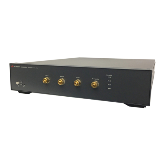
U3020AD01 Introduction Introd uction This document describes how to use the Keysight U3020AD01 Dynamic Accuracy Test Set with a Keysight N5247A PNA-X Network Analyzer. Figure 1 N5247A with the U3020AD01 User’s and Service Guide U3020-90004... -
Page 7: Description
U3020AD01 Description Description The Keysight U3020AD01 Dynamic Accuracy Test Set is designed for use with the PNA-X Network Analyzers and based on the L4490A RF Switch Platform. The U3020AD01 is used to characterize the PNA-X power linearity (dynamic accuracy) designed for maximum measurement accuracy over a 110 dB dynamic range. The signal is controlled via internal attenuators. -
Page 8: General Performance
A functional certificate is supplied for the U3020AD01. There are no internal adjustment in the U3020AD01, therefore an annual calibration is not required. This product has an autoranging line voltage input. Be sure the supply voltage is CAUTION within the specified range. -
Page 9: Environmental Requirements
PNA-X and Test Set to be maintained within ± 1 °C of the ambient temperature at calibration. Dimensions and Space Requirements Standard installation of the U3020AD01 and PNA includes configuration and installation on a customer provided lab bench or table top of adequate size and strength.... -
Page 10: Maximum Power Levels And Performance Characteristics
U3020AD01 General Performance Maximum Power Levels and Performance Characteristics Table 3 Power Levels RF Input/Output Power Damage Levels: SRC 1 IN +30 dBm SRC 2 IN +30 dBm SRC 2 CPLD OUT +30 dBm RCVR OUT +30 dBm Refer to your PNA-X standard documentation specifications to determine the... -
Page 11: Front And Rear Panel Features
• SRC 2 CPLD OUT (Coupler Out) Instrument State LEDs When the power is applied to the U3020AD01, the instrument enters its power-on sequence which requires several seconds to complete. The LEDs provide information on the state of the instrument during power-on and during upgrades of the instrument firmware. - Page 12 U3020AD01 Front and Rear Panel Features Table 5 LED Definitions and Instrument States Color Instrument State ATTN Off Instrument in “ready” state LAN connection established LAN Green Green - instrument has an IP address Firmware download complete ATTN...
- Page 13 U3020AD01 Front and Rear Panel Features Figure 3 Rear Panel GPIB Line Module GPIB Connector This connector allows the Test Set to be connected directly to a controller. The instrument is controlled over Local Area Network (LAN). Line Mod ule The line module contains the power cord receptacle.
-
Page 14: System Setup
U3020AD01 System Setup System Setup Add ing Instruments to the Interface This section contains information to configure the U3020A LAN and GPIB interfaces using Keysight IO Libraries “Connection Expert Utility.” Configuring the LAN Interface 1. Connect the Test Set to the PC. -
Page 15: Locating The Instrument
U3020AD01 System Setup Locating the Instrument Keysight Connection Expert opens with a “Welcome Screen,” and a window similar to that shown in Figure 4. The available computer interfaces are configured during installation of the Keysight IO Libraries and are displayed in the left column (Explorer Pane). The properties of the configured interface are displayed in the right column (Propertied Pane). -
Page 16: Configuring The Gpib Interface
U3020AD01 System Setup Configuring the GPIB Interface Programming access to the Test Set is also available through the instrument's GPIB interface. The GPIB connector is located on the rear panel of the instrument. 1. Select the Keysight Control icon > Keysight Connection Expert. If a GPIB card is installed in your computer, the GPIB interface was configured during installation of the IO libraries and is displayed in the Explorer Pane of the “Welcome”... -
Page 17: Controlling The Test Set And Making Measurements
U3020AD01 System Setup Controlling the Test Set and Making Measurements Keysight U3020A is a “slave” instruments. A controller must be used to control the Test Set. There are two methods that can be used to control the Test Set. • Using LAN connection •... - Page 18 U3020AD01 System Setup Description This command disable or enable the use of Auto-IP standard to automatically assign an IP address to the U3020A when on a network that does not have DHCP servers. Syntax SYSTem:COMMunicate:LAN:AUTOip {OFF|0|ON|1} SYSTem:COMMunicate:LAN:AUTOip? Example The following command disable the Auto-IP:...
- Page 19 U3020AD01 System Setup Description This command assigns the IP address of the Domain Name System (DNS) server. Contact your network administrator to determine if DNS is being used and for the correct address. Syntax SYSTem:COMMunicate:LAN:DNS <address> SYSTem:COMMunicate:LAN:DNS? If you change the DNS address, you must cycle power on the U3020A to activate NOTE the new address.
- Page 20 U3020AD01 System Setup Description This command assigns a Default Gateway for the U3020A. The specified IP Address sets the Default Gateway which allows the instrument to communicate with systems that are not on the local subnet. Thus, this is the Default Gateway where packets are sent which are destined for a device not on the local subnet, as determined by the Subnet Mask setting.
- Page 21 U3020AD01 System Setup GPIB Configuration Commends Description This command assigns a GPIB address to the U3020A. Syntax SYSTem:COMMunicate:GPIB:ADDRess <address> SYSTem:COMMunicate:GPIB:ADDRess? If you change the GPIB address, you must cycle power on the U3020A to activate NOTE the new address. Example...
- Page 22 U3020AD01 System Setup Controlling Test Set Attenuator Settings Description This command executes the specified factory defined sequence from the non-volatile memory. If the specified sequence name not currently stored in the memory, due to corrupted program or accidentally deleted, an error will be generated.
- Page 23 U3020AD01 System Setup Theory of Operation This section provides a general description of the U3020A Dynamic Accuracy Test Set. This is followed by a more detailed operating theory. The operation of each group is described briefly to the assembly level only. Detailed component level circuit theory is not provided.
- Page 24 U3020AD01 System Setup Controller Mod ule Inside the controller module there are two main components, the AC-DC power supply and controller board. The AC-DC power supply is a 12V/65W power supply that is converted to various voltages by means of DC-DC converter inside the module. It provides regulated voltages to all assemblies in the Test Set as well as following voltages to drive programmable step attenuator in the Test Set.
-
Page 25: Making Measurements And Functional Tests
• 85032B Calibration Kit (50 W, Type-N or equivalent) There are no adjustments required for the Keysight U3020AD01 Test Set. The U3020AD01 Test Set is designed to be placed near the network analyzer on a bench top and connected as shown in... - Page 26 U3020AD01 Making Measurements and Functional Tests Set up the network analyzer as follows: Refer to the standard PNA documentation for adapter removal. 1. Select [Center Frequency] > [2.5 GHz]. 2. Select [Frequency Span] > [3 GHz]. Perform a full 4-Port adapter removal calibration at the four test ports of the network analyzer.
-
Page 27: Transmission
U3020AD01 Making Measurements and Functional Tests Transmission 1. Connect the cable attached to PORT 1 of the network analyzer to “SRC 1 IN” of the Test Set. 2. Connect the cable from PORT 2 of the network analyzer to “SRC 2 IN” of the Test Set. - Page 28 U3020AD01 Making Measurements and Functional Tests Table 7 Test Record Parameter Nominal Measured Results Operating Frequency 1 GHz to 4 GHz Isolation: (1.8 GHz to 2.2 GHz) RCVR OUT to SRC 1 IN < -45 dB RCVR OUT to SRC 2 IN SRC 1 IN to SRC 2 IN <...
-
Page 29: Service Information
Service Information Service Information There are many other repair and calibration options available from the Keysight Technologies support organization. The options cover a range of service agreements with varying response times. Contact Keysight for additional information on available service agreements for this product. - Page 30 U3020AD01 Service Information Figure 10 U3020AD01 (top view) Power Supply Attenuator Controller Isolator (x4) Attenuator Power Divider Coupler User’s and Service Guide U3020-90004...
-
Page 31: Replaceable Parts
U3020AD01 Service Information Replaceable Parts Special options are built to order, long lead times may be encountered when ordering replacement parts. Table 8 Replaceable Parts Replacement Part Part Number Power divider, 1 to 26.5 GHz 0955-1421 Microwave Coax Isolator (SMA f - f) -
Page 32: Electrostatic Discharge Protection
U3020AD01 Electrostatic Discharge Protection Electrostatic Discharge Protection Electrostatic discharge (ESD) can damage or destroy electronic components. The instrument is shipped in materials that prevent damage from static, and should only be removed from the packaging in an anti-static area ensuring that the correct anti-static precautions are taken. -
Page 33: Safety And Information
Declaration of Conformity A copy of the Declaration of Conformity is available upon request, or a copy is available on the Keysight Technologies web site at http://regulations.corporate.keysight.com/DoC/search.htm Statement of Compliance This product has been designed and tested in accordance with accepted industry standards, and has been supplied in a safe condition. -
Page 34: Before Applying Power
U3020AD01 Safety and Information Before Applying Power Verify that the premises electrical supply is within the range of the instrument. The instrument has an autoranging power supply. If this prod uct is not used as specified, the protection provided by the equipment WARNING could be impaired. -
Page 35: Connector Care And Cleaning Precautions
U3020AD01 Safety and Information Danger of explosion if battery is incorrectly replaced. Replace only with the WARNING same or equivalent type recommended. Discard used batteries accord ing to manufacturer’s instructions. For continued protection against fire hazard replace line fuse only with same WARNING type and rating. -
Page 36: Regulatory Information
U3020AD01 Regulatory Information Regulatory Information This section contains information that is required by various government regulatory agencies. Instrument Markings The instruction documentation symbol. The product is marked with this symbol when it is necessary for the user to refer to the instructions in the documentation. -
Page 37: Battery Collection
Regulatory Information Battery Collection Do not throw batteries away but collect as small chemical waste, or in accordance with your country’s requirements. You may return the battery to Keysight Technologies for disposal. Refer “Contacting Keysight” on page 34 for assistance. -
Page 38: Keysight Support, Services, And Assistance
Keysight for repair. If you wish to send your instrument to Keysight Technologies for service or repair: • Include a complete description of the service requested or of the failure and a description of any failed test and any error message.
Need help?
Do you have a question about the U3020AD01 and is the answer not in the manual?
Questions and answers