
Related Manuals for Keysight Technologies U3047AM08


Summary of Contents for Keysight Technologies U3047AM08
- Page 1 Keysight Technologies U3047AM08 Multiport Test Set Extension User’s and Service Guide...
-
Page 2: Safety Notices
DOCUMENT IS PROVIDED “AS IS,” computer software,” as defined by AND IS SUBJECT TO BEING Federal Acquisition Regulation © Keysight Technologies. 2015 - 2019 CHANGED, WITHOUT NOTICE, IN (“FAR”) 2.101. Pursuant to FAR FUTURE EDITIONS. FURTHER, TO THE 12.212 and 27.405-3 and... -
Page 3: Table Of Contents
Table of Contents U3047AM08 Introduction ..........................6 Description ..........................7 Measurement Application Notes .................... 7 Verifying the Shipment ......................8 Network Analyzer Requirements .................... 8 Available Options ........................9 Test Set Option ........................9 Rack Mounting Kits ....................... 9 Network Analyzer Interface Kit Options ................9 General Specifications ...................... - Page 4 Table of Contents Selecting New S-Parameter Measurement ..............32 N-Port Calibration ......................35 Interface Control Mode ....................... 38 How to Access Interface Control Mode ................39 Using Interface Control Mode ..................40 SCPI Control Mode ......................43 Overview of the SCPI Control ..................43 How to Access the Command Processor ................
- Page 5 Table of Contents Source and Receiver Switch Paths ................. 69 Troubleshooting the Test Set ....................71 Non-RF Failures ....................... 71 RF Performance Failures ....................73 RF Switching Failures ...................... 74 Test Set RF Switching Path ..................... 75 Equipment Required ......................75 Equipment Setup ......................
-
Page 6: Introduction
U3047AM08 Introduction U3047AM08 Introduction This document describes how to use and service the U3047AM08 Multiport Test Set. Figure 1 N5247A PNA-X 4-Port with U3047AM08 Keysight U3047AM08 User's and Service Guide... -
Page 7: Description
U3047AM08 Description Description The Keysight U3047AM08 is a Multiport Test Set that adds 8 ports to extend the 4-port network analyzer to 12 full crossbar test ports with N-Port calibration capability. The Keysight U3047AM08 has the following key features: — 8 test ports (1.85 mm male connectors) —... -
Page 8: Verifying The Shipment
If there is physical damage refer to “Contacting Keysight” on page 90. Keep the damaged shipping materials (if any) for inspection by the carrier and an Keysight Technologies representative. Table 2 U3047AM08 Accessories Supplied... -
Page 9: Available Options
* Previous color version (Agilent Palette 2000) Network Analyzer Interface Kit Options The U3047AM08 requires on of the following kits to interface the test set with your network analyzer. The interface kit model option includes the hardware lock-link and cable kit listed in... -
Page 10: General Specifications
— N5245A and N5247A maximum power is 450 W. — U3047AM08 maximum power is 350 W. This is a Safety Class I Product (provided with a protective earthing ground incorporated in the power cord). The mains plug shall be only be inserted in a socket outlet provided with a protective earth contact. -
Page 11: Environmental Requirements
The network analyzer is heavy. It is recommended that two individuals, or a mechanical lift, be used to lift or transport the instrument. Keysight U3047AM08 User's and Service Guide... -
Page 12: Maximum Power Levels
The power levels must be 3 dB below maximum level to ensure no damage. see Table 6 below. Table 6 Maximum Power Levels Maximum Power Levels U3047AM08 Test Port RF Power Levels: PORT 5-12 +25 dBm U3047AM08 Access Ports: SOURCE OUT +15 dBm CPLR ARM... -
Page 13: Typical Reflection Tracking
−9 dB 26.5 GHz to 43.5 GHz −11 dB −10 dB −10 dB 43.5 GHz to 50 GHz −13 dB −10 dB −11 dB 50 GHz to 67 GHz −14 dB −11 dB −13 dB Keysight U3047AM08 User's and Service Guide... -
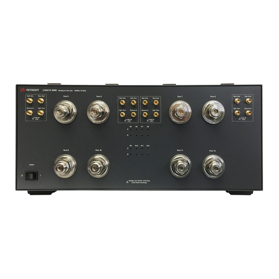
Page 14: Front And Rear Panel Features
The Active LED is on when the test set is connected and addressed by a network analyzer. The LED is off when the test set is in Standby, or not addressed by the network analyzer. Keysight U3047AM08 User's and Service Guide... - Page 15 The detachable power cord is the instrument disconnecting device. It disconnects the mains circuits from the mains supply before other parts of the instrument. The front panel switch is Keysight U3047AM08 User's and Service Guide...
- Page 16 — Fuse (F 8 A/250V, 2110-0342) UL listed and CSA certified. For continued protection against fire hazard, replace fuses, only with same type and ratings. The use of other fuses, circuit breakers or materials is prohibited. Keysight U3047AM08 User's and Service Guide...
- Page 17 U3047AM08 Front and Rear Panel Features Figure 4 Line Fuse Verify that the premise electrical voltage supply is within the range specified on the instrument. Keysight U3047AM08 User's and Service Guide...
-
Page 18: Hardware Lock-Link Installation (U3021-60002)
2. Remove the feet from the bottom of the analyzer. 3. Remove the 2 lower standoffs from the rear panel on the analyzer using a T20 Torx driver. Figure 5 Rear and Bottom Feet Standoffs (x2) Feet (x4) Keysight U3047AM08 User's and Service Guide... - Page 19 6. Install the left and right lock-links onto the test set, as shown in Figure Figure 7 Install Lock-links to the Test Set Right lock-link Left Lock-link N5242-20138 N5242-20139 Screw 0515-2317 (x2) T15 M3.5X0.6 12 mm Keysight U3047AM08 User's and Service Guide...
- Page 20 8. Secure the analyzer’s lower lock-links to the test set’s upper lock-link using the spring–loaded screws. If the analyzer's lock-links are not aligned with the screw holes, loosen the screws securing the feet to the instrument to align and tighten. Figure 9 Locked Keysight U3047AM08 User's and Service Guide...
-
Page 21: N5245A Or N5247A Rf Interface Cable Connections (U3021-60101)
CPLR THRU CPLR THRU U3047-20017 SOURCE OUT SOURCE IN Figure 10 illustrates the final two digits of the part number for each cable. The cables must be connected in the numeric order listed in Table Keysight U3047AM08 User's and Service Guide... - Page 22 U3047AM08 N5245A or N5247A RF Interface Cable Connections (U3021-60101) Figure 10 12-Port Interface Connections 16 (x8) 17 (x8) Keysight U3047AM08 User's and Service Guide...
-
Page 23: Test Set I/O Cable Installation
“System Operational Checks” on page 2. If the problem still exists, perform the “RF Switching Failures” on page 3. If a power hole or other failure still exists, refer to “Contacting Keysight” on page Keysight U3047AM08 User's and Service Guide... -
Page 24: System Operational Checks
Figure 12 on page 25 Figure 13 on page 25 Ports 5 thru 8 Figure 14 on page 26 Figure 15 on page 26 Ports 9 thru 12 Figure 16 on page 27 Figure 17 on page 27 Keysight U3047AM08 User's and Service Guide... - Page 25 Reflection Response Signal Path Diagram Ports 1 to 4 Keysight PNA-X Port 1 Port 3 Port 4 Port 2 Keysight U3047A-M08 RF Diagram Mechnical Switches Port 5 Port 9 Port 6 Port 10 Port 7 Port 11 Port 8 Port 12 Keysight U3047AM08 User's and Service Guide...
- Page 26 Reflection Response Signal Path Diagram Ports 5 to 8 Keysight PNA-X Port 1 Port 3 Port 4 Port 2 Keysight U3047A-M08 RF Diagram Mechnical Switches Port 5 Port 9 Port 6 Port 10 Port 7 Port 11 Port 8 Port 12 Keysight U3047AM08 User's and Service Guide...
- Page 27 Keysight PNA-X Port 1 Port 3 Port 4 Port 2 Keysight U3047A-M08 RF Diagram Mechnical Switches Port 5 Port 9 Port 6 Port 10 Port 7 Port 11 Port 8 Port 12 S1010 S1111 S1212 Keysight U3047AM08 User's and Service Guide...
-
Page 28: Controlling The Test Set
Stepped Sweep is available on all PNA models. 1. On the network analyzer select STIMULUS > Sweep > Sweep Setup. 2. Select Stepped Sweep. 3. Set the Dwell Time to 5 μs > OK. Figure 18 Sweep Setup Keysight U3047AM08 User's and Service Guide... -
Page 29: Rf Path Configuration
Preset by selecting Save > User Preset > Save current state as User Preset. Do not use the factory Preset (User Preset Off), or the analyzer will return to Option 029 path configuration. Figure 19 RF Path Configuration Keysight U3047AM08 User's and Service Guide... -
Page 30: Multiport Mode
The current version of the test set files are available on the web at http://na.support.keysight.com/multiport/testsetsupport.html. Copy the appropriate file to c:\program files\Keysight\Network Analyzer\testsets directory. Figure 20 Test Set Selection Keysight U3047AM08 User's and Service Guide... -
Page 31: External Test Set Control Operation
Select the Port Control down arrow for Ports 9 thru 12. For example, Port 5 can be re-named Port 2. The External Test Set Control-U3047AM08 also allows control of the DUT “Control Lines” on page 49. To change the state from... -
Page 32: Selecting S-Parameter Measurement
S-Parameter Tab: Multiple S-Parameters can be made from the New Trace menu. In the drop-down menu select Trace/Chan > Trace > New Trace -OR- (Instrument > Trace > New Trace). The dialog box allows the selection of any of the 144 S-Parameters. Keysight U3047AM08 User's and Service Guide... - Page 33 For more information on balanced (differential) component measurement, refer to the Application Note 1373-1 and 1373-2 (5988-5634EN and 5988-5635EN) at http://www.keysight.com. In the search menu type “Multiport and Balanced.” Figure 24 Selecting Balanced Measurements Keysight U3047AM08 User's and Service Guide...
- Page 34 Controlling the Test Set Receivers Tab The S-Parameter measurements can be ratioed with selectable Denominators for each port and receiver. Refer to the standard network analyzer documentation for more information. Receiver Measurements Figure 25 Keysight U3047AM08 User's and Service Guide...
-
Page 35: N-Port Calibration
Measurement errors can be a result of firmware algorithms. Consult with Keysight Service or firmware web page for the latest Option 551 firmware revisions and history. http://na.support.keysight.com/pna/firmware/ Figure 26 ECal Characterization and Cal Wizard Keysight U3047AM08 User's and Service Guide... - Page 36 Measure reflection and confirm the return loss is as expected. If the result is not as expected, repeat the calibration without the test set and ensure that the network analyzer is in standard (non-multiport) mode. Keysight U3047AM08 User's and Service Guide...
- Page 37 If measurement errors occur, ensure the newest version of firmware is installed on the network analyzer. Measurement errors can be a result of firmware algorithms. Consult with Keysight Service or firmware web page for the latest Option 551 firmware revisions and history. http://na.support.keysight.com/pna/firmware/. Keysight U3047AM08 User's and Service Guide...
-
Page 38: Interface Control Mode
— Control data is sent in the following order and this order cannot be changed: Refer to the Help menu. 1. GPIB Command - BEFORE 2. Handler I/O Control 3. Test Set I/O Control (addr.data) 4. Dwell After Command 5. Aux I/O Output Voltage Keysight U3047AM08 User's and Service Guide... -
Page 39: How To Access Interface Control Mode
Information regarding this application can be found in the network analyzer Help menu, Interface Control. The application is shown below. Figure 29 Accessing Interface Control Mode Keysight U3047AM08 User's and Service Guide... -
Page 40: Using Interface Control Mode
The quantity of test set I/O entries that can be entered is limited by the available memory of the network analyzer. Refer to the Address and Data example on page Keysight U3047AM08 User's and Service Guide... - Page 41 Interface control uses an *.xml file type. An example file is stored on the network analyzer hard drive. You can recall it into the dialog, or you can open and edit it with a word processor, such as Word Pad. Keysight U3047AM08 User's and Service Guide...
- Page 42 Controlling the Test Set Applies the settings and closes the dialog box. Cancel: Help: Does not apply changes that were made and closes the dialog box. Provides additional information for using the interface control application. Keysight U3047AM08 User's and Service Guide...
-
Page 43: Scpi Control Mode
Command Processor Console in the network analyzer's Help menu. — Command Processor settings can not be saved or recalled. — Address and data can be written from the Command Processor. Keysight U3047AM08 User's and Service Guide... -
Page 44: How To Access The Command Processor
(System Setup > Remote Interface > SCPI Monitor Input > Show SCPI Parser Console). 2. Check the SCPI Command Processor Console box. Figure 31 Command Console for 'A' Model Analyzers Command Console for 'B' Model Analyzers Figure 32 Keysight U3047AM08 User's and Service Guide... -
Page 45: Scpi Command Processor Console
This second command feeds the newly created measurement named “ch1_S10_10” to trace 2 on the PNA-X so that it will be displayed on the PNA-X screen. DISP:WIND1:TRAC2:FEED 'ch1_S10_10' NOTE: Here are syntax format examples for single digit S-parameters: ‘ch1_S99’ ‘ch1_S22’ ‘ch1_S9_10’ ‘ch1_S10_9’ Keysight U3047AM08 User's and Service Guide... - Page 46 Address and Data values are separated by a comma. Commands should be separated by a new line, or carriage return. For example: CONT:EXT:TEST:DATA <address>,<data> CONT:EXT:TEST:DATA 0,0 Example: CONT:EXT:TEST:DATA 0,0 Figure 34 Method 2 - Using Test Set Address and Data Values Keysight U3047AM08 User's and Service Guide...
-
Page 47: Address And Data Values
Table 10 Test Port Address and Data Values Address Source Path Receiver Path Data Ports Ports Ports Ports Refer to on page 66 for in-depth Figure 47, “U3047AM08 RF Block Diagram,” RF path information. Keysight U3047AM08 User's and Service Guide... - Page 48 Address and Data Example 1 (Port 5 and 6) Keysight PNA-X Port 1 Port 3 Keysight U3047A-M08 RF Diagram Mechnical Switches 16.16 Port 5 Port 9 Port 6 Port 10 Receiver Port Source Port Keysight U3047AM08 User's and Service Guide...
-
Page 49: Control Lines
100 mA (each line) Control Line DC resistance < 10 Ω (each line) Voltage Range: Positive Input 0 to +5 V Negative Input –5 to 0 V Internal Variable Voltage +2 to +5 V Keysight U3047AM08 User's and Service Guide... - Page 50 Internal voltage output, adjusted with the trimmer on the rear panel. Positive Input Connection for internal (pin 12) or external positive voltage supply. Negative Input Connection for ground (pin 15) or external negative voltage supply. ground terminal Keysight U3047AM08 User's and Service Guide...
-
Page 51: Internal Voltage Supply Configuration
Figure 37 Internal DC Power Configuration (rear panel view) Line 1 Line 2 (Rear Panel View) TO DUT (Only required Lines) Line 8 2 to 5 Vdc TEST SET Keysight U3047AM08 User's and Service Guide... -
Page 52: External Voltage Supply Configuration
Test Set to the DUT and External DC Power Supply Line 1 Line 2 (Rear Panel View) TO DUT (Only required Lines) DC Power Supply Line 8 2 to 5 Vdc Positive: 0 to 5 Vdc Negative: 5 to 0 Vdc TEST SET Keysight U3047AM08 User's and Service Guide... -
Page 53: Setting The Control Lines With Address And Data Values
DUT Control Line 6 set to logic low or connected to Pin 14 DUT Control Line 7 set to logic low or connected to Pin 14 DUT Control Line 8 set to logic low or connected to Pin 14 Keysight U3047AM08 User's and Service Guide... - Page 54 3. The SUM of the <data> values = 6 4. Front panel network analyzer Interface Control Mode line entry = 112.6 > Since all control lines have the same <address>, only one "<address>.<data>" command line is needed to control all 8 lines. Keysight U3047AM08 User's and Service Guide...
-
Page 55: Cal Kit Operational Check
Cal Kit Operational Check The following procedure can be used to confirm the 1-Port Cal operation of an ECal module or Mechanical Cal Kit with the U3047AM08 Test Set. The operation verification limits provided ensure that your U3047AM08 and network analyzer are operating properly. Refer to “Verifying Cal Kit... -
Page 56: Equipment Required
U3047AM08 Cal Kit Operational Check Equipment Required The Keysight U3047AM08 requires that the user be familiar with the equipment listed. Table 15 Equipment List Description N4694A 1.85 mm ECal Module 10 MHz - 67 GHz (Option 00F or M0F) or 85058B Verification Kit. - Page 57 ECal. If you are not, see “1-Port Calibration and Verification Procedure” on page 58, step 12. Allow the ECal module, test set and network analyzer to warm up for a minimum of 30 minutes. Keysight U3047AM08 User's and Service Guide...
-
Page 58: 1-Port Calibration And Verification Procedure
If you do not have a keyboard, select Save As User Calset > Edit Name and save as 999.x. X is the port number you are calibrating. Use the numeric keypad on the network analyzer front panel to enter “999.1.” Keysight U3047AM08 User's and Service Guide... - Page 59 11. Compare the Reflection Tracking (1,1) trace to the appropriate limits in Table 7 on page 13. The trace should be above the limit. 12. Repeat steps 10 and 11 for Cal Sets “999.1” thru “999.12” (12-Port). Keysight U3047AM08 User's and Service Guide...
- Page 60 U3047AM08 Cal Kit Operational Check Figure 42 Typical Reflection Tracking Trace (Ports 1 to 4) Figure 43 Typical Reflection Tracking Trace (Ports 5 to 8) Keysight U3047AM08 User's and Service Guide...
- Page 61 U3047AM08 Cal Kit Operational Check Figure 44 Typical Reflection Tracking Trace (Ports 9 to 12) Keysight U3047AM08 User's and Service Guide...
-
Page 62: Verifying Cal Kit Operational Check Failure
4. Select [Response] > Cal > More > ECal > ECal Confidence Check -OR- (Response > Cal > ECal Confidence Check...). 5. ECal Confidence Check dialog box: Click Change Measurement and select the test port S-parameter > Apply > OK. Click Read Module Data. Keysight U3047AM08 User's and Service Guide... - Page 63 Figure 45 ECal Confidence Check 6. Select ECal Module dialog box. Select the ECal Module you are using, and select the ECal Module Memory and Factor ID > OK. Figure 46 ECal Confidence Check Trace Keysight U3047AM08 User's and Service Guide...
-
Page 64: Service Information
U3047AM08 Service Information Service Information This section provides information to troubleshoot and repair the U3047AM08 “Keysight Support, Services, and Assistance” on page 90 Test Set. Refer to for information on returning your test set to Keysight Technologies. No operator serviceable parts inside. Refer servicing to qualified personnel. - Page 65 Front Panel LED Board (programmed) N5261-60005 Test Set Control Board (programmed) N5261-60006 DUT Control Board U3020-63223 SW Interface Board 25 V, programmed U3025-60068 U3047AM08 User’s and Service Guide U3047-90004 RF Cable, Semi-rigid U3047-20016 RF Cable, Semi-rigid U3047-20017 Keysight U3047AM08 User's and Service Guide...
-
Page 66: System Block Diagram
U3047AM08 Service Information System Block Diagram Figure 47 U3047AM08 RF Block Diagram Keysight U3047AM08 User's and Service Guide... - Page 67 U3047AM08 Service Information Figure 48 Electrical Block Diagram Keysight U3047AM08 User's and Service Guide...
-
Page 68: Theory Of Operation
Test Set I/O for control of the RF switch paths (through the Switch Interface board (U3025-60068). The front panel “Active” and port LEDs are on only when the network analyzer has addressed the U3047AM08 test set. The rear panel fan is on when the controller board supplies are operational. -
Page 69: Rf Coupler
Port 8 and 12. In the state shown in the block diagram, switch 40 routes the RF Source back to the network analyzer Port 2, and the test set Source path to Ports 8 and 12 are terminated. Keysight U3047AM08 User's and Service Guide... - Page 70 Port 8 and 12. In the state shown in the block diagram, switch 43 routes the Port 2 Coupler Arm to the Receiver, and test set Ports 8 and 12 Coupler Arm paths are terminated. Keysight U3047AM08 User's and Service Guide...
-
Page 71: Troubleshooting The Test Set
U3047AM08 Service Information Troubleshooting the Test Set If the U3047AM08 is not operating properly, use the following procedures to isolate and repair the type of failure encountered. It is recommended that a qualified service technician perform the following procedures. Refer to the Keysight PNA Series: Service & Support Home Page at: http://na.support.keysight.com/pna... - Page 72 = LED INDICATOR Instrument Rear Panel 4. Front panel R and S indicator LED check. a. If the indicators are not operating, continue to “RF Switching Failures” step and step 2. Keysight U3047AM08 User's and Service Guide...
-
Page 73: Rf Performance Failures
Figure 3 on page RF Performance Failures If the U3047AM08 operates correctly, but RF performance fails the operational test. The following procedures can be used to isolate the failed component. Suspect the coax switches (N1811-60019), RF cables, or coupler (5087-7754). -
Page 74: Rf Switching Failures
Driver board. If the LEDs remain Off, replace the Controller board. b. If the Status LEDs are On and the front panel Active LED is On, suspect the front panel LED board or the ribbon cable (replace as needed). Keysight U3047AM08 User's and Service Guide... -
Page 75: Test Set Rf Switching Path
RF switches for this testing. After making your entry, select <OK> to execute the command. To return back for further entries, select Interface Control on the network analyzer display. Keysight U3047AM08 User's and Service Guide... -
Page 76: Cable Connections
Figure 50 on page 77 Source IN to Ports 12 64.2 P12 CPLR, S40, 41 & 42 Figure 51 on page 77 1. Use the Source IN port associated with this group of test ports. Keysight U3047AM08 User's and Service Guide... - Page 77 U3047AM08 Service Information Figure 50 Source IN to Ports 5 to 8 Path Response Figure 51 Source IN to Ports 9 to 12 Path Response Keysight U3047AM08 User's and Service Guide...
- Page 78 Figure 52 on page 79 RCVR OUT to Ports 12 64.32 P12 CPLR, S43, 44 & 45 Figure 53 on page 79 1. Use the RCVR OUT port associated with this group of test ports. Keysight U3047AM08 User's and Service Guide...
- Page 79 U3047AM08 Service Information Figure 52 RCVR OUT to Ports 5 to 8 Path Response Figure 53 RCVR OUT to Ports 9 to 12 Path Response Keysight U3047AM08 User's and Service Guide...
- Page 80 Port 7 & 11 Source IN to CPLR THRU 32.0 Port 8 & 12 Source IN to CPLR THRU 64.0 Figure 54 Source IN to CPLR THRU & RCVR OUT to CPLR ARM Path Response Keysight U3047AM08 User's and Service Guide...
- Page 81 RCVR OUT to CPLR ARM Port 6 & 10 RCVR OUT to CPLR ARM 16.0 Port 7 & 11 RCVR OUT to CPLR ARM 32.0 Port 8 & 12 RCVR OUT to CPLR ARM 64.0 Keysight U3047AM08 User's and Service Guide...
- Page 82 U3047AM08 Service Information Figure 55 Test Set Top View DUT Control Bd Test Set Control Bd (Bottom Bd) Switch Interface Bd (Top Bd) Receiver Switches (x12) Test Ports (x8) Keysight U3047AM08 User's and Service Guide...
- Page 83 U3047AM08 Service Information Figure 56 Test Set Bottom View Line Mod ule Power Supply Fuse (x2) Source Switches (x12) Keysight U3047AM08 User's and Service Guide...
-
Page 84: Safety And Regulatory Information
Declaration of Conformity A copy of the Declaration of Conformity is available upon request, or a copy is available on the Keysight Technologies web site at http://regulations.about.keysight.com/DoC/ Statement of Compliance This product has been designed and tested in accordance with accepted industry standards, and has been supplied in a safe condition. -
Page 85: Before Applying Power
This instrument has auto-ranging line voltage input, be sure the supply voltage is within the specified range and voltage fluctuations do not to exceed 10 percent of the nominal supply voltage. Keysight U3047AM08 User's and Service Guide... -
Page 86: Servicing
To prevent electrical shock, disconnect the Keysight Technologies U3047AM08 from mains electrical supply before cleaning. Use a dry cloth or one slightly dampened with water to clean the external case parts. Do not attempt to clean internally. -
Page 87: Electrostatic Discharge Protection
2. While wearing a grounded wrist strap, grasp the outer shell of the cable connector. 3. Connect the other end of the cable to the test port and remove the short from the cable. Figure 57 ESD Protection Setup Keysight U3047AM08 User's and Service Guide... -
Page 88: Regulatory Information
Forty years is the expected useful life of the product. This symbol on all primary and secondary packaging indicates compliance to China standard GB 18455-2001. South Korean Certification (KC) mark; includes the marking's identifier code which follows the format: MSIP-REM-YYY-ZZZZZZZZZZZZZZ. Keysight U3047AM08 User's and Service Guide... -
Page 89: Battery
Regulatory Information Battery: Do not throw batteries away but collect as small chemical waste, or in accordance with your country’s requirements. You may return the battery to Keysight Technologies for disposal. Refer to “Contacting Keysight” on page 90 for assistance. -
Page 90: Keysight Support, Services, And Assistance
Keysight for repair. If you wish to send your instrument to Keysight Technologies for service or repair: — To improve turn-around time, return your test set along with your network analyzer and cables to Keysight so that we may verify the operation of the complete system. - Page 91 Keysight U3047AM08 User's and Service Guide...
- Page 92 This information is subject to change without notice. © Keysight Technologies 2015 - 2019 Print Date: May 2019 Supersedes: November 2018 U3047-90004 www.keysight.com...
Need help?
Do you have a question about the U3047AM08 and is the answer not in the manual?
Questions and answers