
Related Manuals for Keysight Technologies U3022AM42


Summary of Contents for Keysight Technologies U3022AM42
- Page 1 Keysight Technologies U3022AM42 Multiport Test Set Extension User’s and Service Guide...
- Page 2 INFORMATION CONTAINED HEREIN, software is customarily provided to from Keysight Technologies, Inc. as INCLUDING BUT NOT LIMITED TO THE the public. Accordingly, Keysight governed by United States and IMPLIED WARRANTIES OF provides the Software to U.S.
-
Page 3: Table Of Contents
Table of Contents U3022AM42 Introduction ................6 Description. - Page 4 Table of Contents Controlling the Test Set with N5242A/B............28 Typeface Key Conventions .
- Page 5 Table of Contents ECal Confidence Check ............62 Service Information .
-
Page 6: Introduction
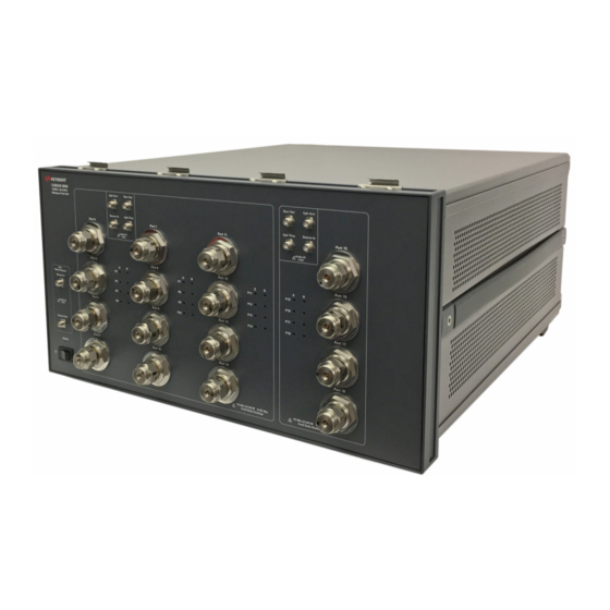
U3022AM42 Introduction Introd uction This document describes how to use and service the U3022AM42 Multiport Test Set Extension. Figure 1 U3022AM42 Multiport Test Set Keysight U3022AM42 User's and Service Guide... - Page 7 U3022AM42 Introduction Figure 2 4-Port N5242B PNA-X with U3022AM42 Keysight U3022AM42 User's and Service Guide...
-
Page 8: Description
• Keysight PNA compatibility with rear panel Test Set I/O interface for operational control. The PNA requires the N-Port calibration option. • The U3022AM42 is directly controlled by the PNA front panel controls or with an external computer connected to the PNA GPIB port. -
Page 9: Verifying The Shipment
Network Analyzer Configuration Requirements 4-Port Options Test Set File System Figure Network Analyzer N5242B PNA-X u3022am42_pnax_p4 Figure 2 on page 7 • Test Set Files - http://na.support.keysight.com/multiport/testsetsupport • Multiport Test Set Support - http://na.support.keysight.com/multiport/ Keysight U3022AM42 User's and Service Guide... -
Page 10: Network Analyzer Interface Kit Options
U3022AM42 Description Network Analyzer Interface Kit Options The U3022AM42 requires on of the following kits to interface the test set with your analyzer. The interface kit model option includes the hardware lock-link and cable kit listed in Table 3. Table 3... -
Page 11: General Specifications
• Air conditioning equipment (or other motor–operated equipment) should not be placed on the same AC line that powers the test set and analyzer. • U3022AM42 maximum power is 350 W. This is a Safety Class I product (provided with a protective earthing ground incorporated in the power cord). -
Page 12: Environmental Requirements
Table 4 Instrument Dimensions Model Weight Height Wid th Depth 50.0 cm 22.15 cm 42.5 cm U3022AM42 14 kg (30.9 lb) (8.7 in) (16.7 in) (19.7 in) Keysight U3022AM42 User's and Service Guide... -
Page 13: Frequency Range And Power Levels
Refer to your analyzer’s specifications to determine the maximum input power levels for the access and test ports, or to optimize the power levels in the receivers. Damage and maximum levels are not necessarily the optimum level. Keysight U3022AM42 User's and Service Guide... -
Page 14: Front And Rear Panel Features
When the two Test Sets are connected together, as in the multi-Test Set system, the first Test Set connected to the PNA-X will never have an "ON" Active LED. Instead, the last Test Set in the I/O cable chain will be showing the "Active LED" status for all. Keysight U3022AM42 User's and Service Guide... -
Page 15: Control Lines And Voltage Adjust
LINE switch. Alternatively, an externally installed switch or circuit breaker (which is readily identifiable and is easily reached by the operator) may be used as a disconnecting device. Keysight U3022AM42 User's and Service Guide... -
Page 16: Power Cords
For continued protection against fire hazard replace line fuse only with same type and rating. The use of other fuses, circuit breakers or materials is prohibited. Figure 5 Line Fuse Verify that the premise electrical voltage supply is within the range specified on the instrument. Keysight U3022AM42 User's and Service Guide... -
Page 17: Hardware Lock-Link Installation (U3021-60005)
2. Remove the feet from the bottom of the analyzer. 3. Remove the two lower standoffs from the rear panel on the analyzer using a T20 torx driver. Figure 6 Rear Bottom Feet & Standoffs Standoffs (x2) Feet (x4) Keysight U3022AM42 User's and Service Guide... - Page 18 6. Install the left and right lock-links onto the test set, as shown in Figure 8. Figure 8 Install Lock-links onto the Test Set Screw 0515-2317 (x2) Right lock-link Left lock-link T15 M3.5X0.6 12 mm N5242-20206 N5242-20207 Keysight U3022AM42 User's and Service Guide...
- Page 19 8. Secure the analyzer’s lower lock-links to the test set upper locking feet using the spring–loaded screws. If the analyzer’s lower lock-links are not aligned with the screw holes, loosen the screws securing the feet to the instrument to align and tighten. Lock-link Secured Figure 10 Keysight U3022AM42 User's and Service Guide...
-
Page 20: N5242A/B Rf Interface Cable Connections
Port 2 SOURCE OUT Port 15-18 SOURCE IN U3042-20125 Port 2 RCVR B IN Port 15-18 RCVR OUT U3042-20127 Port 2 CPLR ARM Port 15-18 CPLR ARM Refer to “Interconnect Cable Verification” on page Keysight U3022AM42 User's and Service Guide... - Page 21 PNA-X RF Interface Cable Connections 20 22 28 26 Apply an overlay label to PNA-X Port 3 and 4: "3" to be "19" and "4" to be "20." Continue to “Test Set I/O Cable Installation” on page Keysight U3022AM42 User's and Service Guide...
-
Page 22: Test Set I/O Cable Installation
“System Operational Check” on page 2. If the problem still exists, perform the “RF Switching Failures” on page 3. If a power hole or other failure still exists, refer to “Contacting Keysight” on page Keysight U3022AM42 User's and Service Guide... -
Page 23: System Operational Check
Figure 19 on page 27 Ports 15 to 18 Figure 18 on page 27 Figure 17 on page 26 Figure 19 on page 27 The trace ripple (peak-peak variation) is normal for this raw uncorrected measurement. Keysight U3022AM42 User's and Service Guide... - Page 24 U3022AM42 System Operational Check Figure 13 Typical Reflection Response Port 1 Figure 14 Typical Reflection Response Port 2 Keysight U3022AM42 User's and Service Guide...
- Page 25 U3022AM42 System Operational Check Figure 15 Reflection Response Signal Path Diagram Port 1 to 4 Keysight U3022AM42 User's and Service Guide...
- Page 26 U3022AM42 System Operational Check Figure 16 Typical Reflection Response Ports 3 to 14 Figure 17 Reflection Response Signal Path Diagram Ports 3 and 5 Keysight U3022AM42 User's and Service Guide...
- Page 27 System Operational Check Figure 18 Typical Reflection Response Ports 15 to 18 Figure 19 Reflection Response Signal Path Diagram Ports 14 and 18 Response 10 MHz to 500 MHz is normal for the PNA-X couplers only. Keysight U3022AM42 User's and Service Guide...
-
Page 28: Controlling The Test Set With N5242A/B
Stepped Sweep is available on all PNA models. 1. On the PNA select STIMULUS > Sweep > Sweep Setup. 2. Select Stepped Sweep. 3. Set the Dwell Time to 5 μs > OK. Figure 20 Sweep Setup Keysight U3022AM42 User's and Service Guide... -
Page 29: Sweep Setup For Pna-X N52Xxb Models
1. Select [Sweep] > Sweep Setup > Timing. 2. Select Timing tab. 3. Select Sweep Mode: Stepped. 4. Deselect Time: Auto Sweep Time. 5. Set Dwell Time > Apply > OK. Figure 21 Sweep Setup, N52xxB Keysight U3022AM42 User's and Service Guide... -
Page 30: Multiport Mode
2. In Multiport mode, PNA Port 3 becomes Test Port 19 and PNA Port 4 becomes Test Port 20. 3. Standalone PNA mode supports all standard PNA option applications. To control the test paths in the Standalone PNA mode, see "Setting the Analyzer to Standalone Mode" on page Keysight U3022AM42 User's and Service Guide... -
Page 31: How To Access Multiport Mode
(Instrument > Setup > External Hardware > Multiport > Multiport Configuration...). 2. Select U3022AM42 (20-Port System) from the drop-down menu and select Restart as a multiport PNA with this testset > OK. See Figures 24 and 25 below. The analyzer will restart the network application with the test set interface features. -
Page 32: External Test Set Control Feature
This menu will allow the physical Ports 1 thru 20 to be identified as any port for your convenience. For example, Port 5 can be named Port 2. The External Test Set Control-U3022AM42 also allows control of the DUT control lines, refer “Control Lines” on page 50. -
Page 33: Trace Measure S-Parameter
S-Parameter Tab: Multiple S-Parameters can be made from the New Trace menu. In the drop-down menu select Trace/Chan > New Trace -OR- (Instrument > Trace > New Trace). The dialog box allows the selection of any of the 400 S-Parameters. Figure 27 New S-Parameter Measurement Keysight U3022AM42 User's and Service Guide... -
Page 34: Balanced Tab
Figure 28 Selecting Balanced Measurements Receivers Tab: The S-Parameter measurements can be ratioed with selectable Denominators for each port and receiver. Refer to the standard PNA-X documentation for more information. Figure 29 Receiver Measurements Keysight U3022AM42 User's and Service Guide... -
Page 35: Rf Path Configuration For Analyzer With Noise Figure Capability
Utilities System> Configure > Preferences -OR- (Utility > System > System Setup > Preferences > User Preset). If not, select Meas: Port 1 Noise Tuner Switch is set to external. Figure 30 RF Path Configuration Keysight U3022AM42 User's and Service Guide... -
Page 36: N-Port Calibration
Response > Cal Wizard > Characterize ECal Module -OR- (Response > Cal > Other Cals > ECal...) and follow the prompts. 2. Save the ECal characterization file. Refer to the Help menu for characterizing information. Figure 31 ECal Characterization Keysight U3022AM42 User's and Service Guide... - Page 37 If measurement errors occur, ensure the newest version of firmware is installed on the PNA. Measurement errors can be a result of firmware algorithms. Consult with Keysight Service or firmware web page for the latest PNA firmware revisions and history. http:\\na.support.keysight.com\pna\firmware\firmware Keysight U3022AM42 User's and Service Guide...
-
Page 38: Interface Control
• Control data is sent in the following order and this order cannot be changed: Refer to the PNA Help menu. 1. GPIB Commands - BEFORE 2. Handler I/O Control 3. Test Set I/O Control (addr.data) 4. Dwell After Command 5. Aux I/O Output Voltage Keysight U3022AM42 User's and Service Guide... -
Page 39: How To Access Interface Control Settings
Please review this application before connecting the test set to the PNA. Information regarding this application can be found in the PNA Help menu, Interface Control. The application is shown in Figure 34 below. Figure 34 Interface Control Application Keysight U3022AM42 User's and Service Guide... -
Page 40: Using Interface Control Mode
The front panel Enter key can be used to insert a new line into the field. The quantity of test set I/O entries that can be entered is limited by the available memory of the analyzer. Address and Data example: addr.data (3) 16.1 32.2 Keysight U3022AM42 User's and Service Guide... - Page 41 Word Pad. Applies the settings and closes the dialog box. Cancel: Does not apply changes that were made and closes the dialog box. Help: Provides additional information for using the interface control application. Keysight U3022AM42 User's and Service Guide...
-
Page 42: Scpi Control Mode
Utility > System > Configure > SICL/GPIB/SCPI -OR- (System Setup > Remote Interface > SCPI Monitor Input > Show SCPI Parser Console), check SCPI Command Processor Console box. Figure 36 Command Console for 'A' Model Analyzers Keysight U3022AM42 User's and Service Guide... -
Page 43: Scpi Command Processor Console
Method 1 provides more PNA-X control capability than Method 2. The following example shows two executable commands needed to create an S-parameter measurement on your Multiport system. Method 1 - Using GPIB/SCPI Command Values Figure 38 Keysight U3022AM42 User's and Service Guide... - Page 44 Address and Data values are separated by a comma. Commands should be separated by a new line, or carriage return. For example: CONT:EXT:TEST:DATA <address>,<data> CONT:EXT:TEST:DATA 0,0 Example: CONT:EXT:TEST:DATA 0,0 Method 2 - Using Test Set Address and Data Values Figure 39 Keysight U3022AM42 User's and Service Guide...
-
Page 45: Address And Data Values
Controlling the Test Set with N5242A/B. The RF signal path configurations can be set by using the preprogrammed Address and Data values of the U3022AM42. Using the Test Set Address and Data values is only available while the system is in Standalone Mode. - Page 46 32.162 S15_15 to S18_18 measurements) Port > Adds.Data 64.17 64.34 64.51 64.68 > Note: System Ports 19 and 20 are not connected to the Test Set, therefore do not require “Address & Data” values. Keysight U3022AM42 User's and Service Guide...
- Page 47 85,0,17 CONT:EXT:TEST:DATA 16,0; delay 20ms CONT:EXT:TEST:DATA 32,17; delay 20ms Port Address Data CONT:EXT:TEST:DATA 64,34; delay 20ms To add the Ext Noise Source path to port 7, change "32,17" to "32,145" as shown in Table Keysight U3022AM42 User's and Service Guide...
- Page 48 U3022AM42 Address and Data Values Figure 40 Example 1, Address and Data Entry for Port 7 and 16, Tx/Rx Setup Port 7 TxRx (S77) Setup Code Entry Port 16 TxRx (S16_16) Setup Code Entry Keysight U3022AM42 User's and Service Guide...
- Page 49 Again, ports that share a common address will get their data values summed for our final entry: 0.80 16.6 32.34 SCPI Command Entry Method CONT:EXT:TEST:DATA 0,80; delay 20ms CONT:EXT:TEST:DATA 16,6; delay 20ms CONT:EXT:TEST:DATA 32,34; delay 20ms Keysight U3022AM42 User's and Service Guide...
-
Page 50: Control Lines
Voltage Range: Positive Input 0 to +5 V Negative Input –5 to 0 V Maximum Current 100 mA (in total of each line) < 10 Ω Impedance Range of Variable Voltage +2 to +5 V Keysight U3022AM42 User's and Service Guide... - Page 51 Input a signal that is outputted when each line is low from Negative Input the external DC power supply. Able to output 0 V as low from the each line by connecting to pin 15. ground terminal Keysight U3022AM42 User's and Service Guide...
-
Page 52: Internal Voltage Supply Configuration
You may only connect pin 12–13, and pin 14–15, damage may result if any other paths are short-circuited. Figure 42 Internal DC Power Configuration (rear panel view) Line 1 Line 2 (Rear Panel View) TO DUT (Only required Lines) Line 8 2 to 5 Vdc TEST SET Keysight U3022AM42 User's and Service Guide... -
Page 53: External Voltage Supply Configuration
Line 1 Line 2 (Rear Panel View) TO DUT (Only required Lines) DC Power Supply Line 8 + Gnd 2 to 5 Vdc Positive: 0 to 5 Vdc Negative: 5 to 0 Vdc TEST SET Keysight U3022AM42 User's and Service Guide... -
Page 54: Setting The Control Lines With Address And Data Values
DUT Control Line 6 set to logic low or connected to Pin 14 DUT Control Line 7 set to logic low or connected to Pin 14 DUT Control Line 8 set to logic low or connected to Pin 14 Keysight U3022AM42 User's and Service Guide... - Page 55 3. The SUM of the <data> values = 6 4. Front panel analyzer Interface Control Mode line entry = 112.6 > OK. Since all control lines have the same <address>, only one "<address>.<data>" command line is needed to control all 8 lines. Keysight U3022AM42 User's and Service Guide...
-
Page 56: Cal Kit Operational Check
N4691B 3.5 mm ECal Module 300 kHz to 26.5 GHz (Option 00F or M0F) or Mechanical cal kit 85052B or 85052D N5242A Option 400 and 551 Set of interconnect cables (PNA and test set) Keysight U3022AM42 User's and Service Guide... -
Page 57: Verification Limits
Only a functional certificate is provided for the test set. It is recommended that you return your instrument to Keysight Technologies for servicing or repair if the test set and network analyzer performance exceed the operational verification limits. -
Page 58: Cal Kit Operational Check Procedure
Utility > System > Configure > Multiport Capability -OR- (Instrument > Setup > External Hardware > Multiport > Multiport Configuration...). Select Restart as Multiport PNA with this Test Set and select U3022AM42 (20-Port) from the drop-down menu > OK. Refer to Figures 23 and 24 on page 5. -
Page 59: 1-Port Calibration Procedure
(Response > Cal > Cal Sets & Cal Kits > ECal Confidence Check). Select Change Measurement and select the test port S-Parameter > Apply > OK > Read Module Data. For further information refer to the Help menu. Figure 45 Calibration Complete Keysight U3022AM42 User's and Service Guide... -
Page 60: Cal Set Verification
4. Compare the Reflection Tracking (1,1) trace to the appropriate limits in Table 13 on page 57. Use the Markers function to measure the trace values. 5. Repeat step 3 and step 4 for Cal Sets “999.1” thru “999.18” (18-Port). Keysight U3022AM42 User's and Service Guide... - Page 61 Standard Reflection Tracking Trace (Ports 3 to 18) Response from 10 MHz to 500 MHz is normal due to the PNA-X couplers in comparison to the test set bridges. The bridges have more gain in the coupled RF path. Keysight U3022AM42 User's and Service Guide...
-
Page 62: Verifying Cal Kit Operational Check Failure
5. Click Change Measurement and select the test port S-parameter Apply > OK. Click Read Module Data. 6. Select the ECal module you are using, and select ECal Module Memory > Factory > OK. Figure 49 ECal Confidence Check Keysight U3022AM42 User's and Service Guide... -
Page 63: Service Information
These servicing instructions are for use by qualified personnel only. To avoid electrical shock, do not perform any servicing unless you are qualified to do so. Replaceable Parts The following replaceable parts are available from Keysight Technologies “Find-A-Part” system on the web at http://www.keysight.com/my/faces/fapHomePage.jspx. Table 14 Available Replacement Parts (SPO) Keysight ... - Page 64 Available Replaceable Parts (M42) Keysight Description Part Number U3022AM42 User’s Guide U3022-90012 LED Status Board N5261-60005 Switch Interface Board U3025-60062 Controller Board N5261-60006 Power Switch and LED Z5623-60221 PNA-X Lock-link kit U3021-60005 PNA-X Cable kit U3021-60077 Keysight U3022AM42 User's and Service Guide...
-
Page 65: System Block Diagrams
U3022AM42 System Block Diagrams System Block Diagrams Figure 50 System RF Block Diagram Keysight U3022AM42 User's and Service Guide... - Page 66 U3022AM42 System Block Diagrams Figure 51 U3022AM42 RF Block Diagram Keysight U3022AM42 User's and Service Guide...
-
Page 67: Theory Of Operation
RF switch paths (through the Switch Interface board (U3025-60062). The front panel “Active” and port LEDs are on only when the network analyzer has addressed the U3022AM42 test set. The rear panel fan is on when the controller board supplies are operational. -
Page 68: Rf Bridge
Provides control of the Rcvr Out path to network analyzer Port 2 (Cplr Arm) and test set Port 15, 16, 17, and 18. S37 - Source to Ports (1, and 3-14) Provides control of the Noise Source path. Keysight U3022AM42 User's and Service Guide... -
Page 69: Troubleshooting The Test Set
Troubleshooting the Test Set Troubleshooting the Test Set If the test set exhibits performance failures, refer to "U3022AM42 RF Block Diagram" on page 66 "Test Set Diagram" on page 71 to help diagnose the issues. Refer to "U3022AM42 Test Set Path Characteristics"... -
Page 70: Non-Rf Failures
Set the Standby switch to the on position. Both the rear panel and internal power supply fans should be operational. Verify that the DC indicator LEDs are on as shown in Figure 52. Figure 52 DC Power Status LEDs Keysight U3022AM42 User's and Service Guide... - Page 71 Verify that the control voltage pin connections to the DUT control lines are connected properly. Refer to “Address and Data Values” on page b. Verify that the rear panel DC voltage control adjustment can be set to 5 Vdc. Refer to Figure 4 on page Keysight U3022AM42 User's and Service Guide...
-
Page 72: Rf Switching Failures
6. Set the analyzer to Interface Control Mode: Select Channel > Hard ware Setup > More > Interface Control… -OR- (Instrument > Setup > Internal Hardware > Interface Control...) and click Enable Interface Control box. Keysight U3022AM42 User's and Service Guide... - Page 73 Ext. Source IN to Ports 3-14 Source Figure 59 on page 80 Ext. Source IN to CPLR THRU Source Figure 60 on page 80 Ext. Source OUT to Source IN Source Figure 61 on page 80 Keysight U3022AM42 User's and Service Guide...
-
Page 74: Source And Receiver Path Tests
P16 CPLR, S40 Source IN to Port 17 64.3 P17 CPLR, S40 Source IN to Port 18 64.4 P18 CPLR, S40 1. Use the Source IN port associated with this group of test ports. Keysight U3022AM42 User's and Service Guide... - Page 75 U3022AM42 Troubleshooting the Test Set Source IN to Ports 3 to 14 Path Response Figure 54 Figure 55 Source IN to Ports 15 to 18 Path Response Keysight U3022AM42 User's and Service Guide...
- Page 76 P16 CPLR, S41 RCVR OUT to Port 17 64.48 P17 CPLR, S41 RCVR OUT to Port 18 64.64 P18 CPLR, S41 1. Use the RCVR OUT port associated with this group of test ports. Keysight U3022AM42 User's and Service Guide...
- Page 77 U3022AM42 Troubleshooting the Test Set Figure 56 RCVR OUT to Ports 3 to 14 Path Response Figure 57 RCVR OUT to Ports 15 to 18 Path Response Keysight U3022AM42 User's and Service Guide...
- Page 78 <Address>.<Data> Components Port 1 RCVR OUT to CPLR ARM 16.0 32.0 Port 2 RCVR OUT to CPLR ARM 64.0 Figure 58 Source IN to CPLR THRU or RCVR OUT to CPLR ARM Path Response Keysight U3022AM42 User's and Service Guide...
-
Page 79: Ext. Source And Test Ports 3-14 Path Tests
P11 CPLR, S30 16.6 32.128 Ext. Source IN to CLPR THRU S30, S37 16.0 32.128 Ext. Source OUT to Source IN 16.0 32.128 1. Use the Source IN port associated with this group of test ports. Keysight U3022AM42 User's and Service Guide... - Page 80 Figure 59 Ext. Noise Source IN to Ports 3 to 14 Path Response Figure 60 Ext. Noise Source IN to CLPR THRU Path Response Figure 61 Ext. Noise Source OUT to Source IN Path Response Keysight U3022AM42 User's and Service Guide...
- Page 81 U3022AM42 Troubleshooting the Test Set Figure 62 Top Internal View Coupler/Bridge (x16) SW40 SW20 SW30 SW10 SW37 Multiport SW21 Switch (x8) SW11 SW41 SW31 Switch Interface Bd. Control Bd. Control Bd. (bottom) Keysight U3022AM42 User's and Service Guide...
- Page 82 U3022AM42 Troubleshooting the Test Set Figure 63 Bottom Internal View Coupler (x16) Multiport SW10 SW30 SW20 SW40 Switch (x8) SW37 SW21 SW41 SW11 SW31 Fuse (x2) Line Module Power Supply Keysight U3022AM42 User's and Service Guide...
- Page 83 U3022AM42 Troubleshooting the Test Set Figure 64 Side Internal View SW37 Keysight U3022AM42 User's and Service Guide...
-
Page 84: Safety And Regulatory Information
The documentation contains information and warnings that must be followed by the user to ensure safe operation and to maintain the product in a safe condition. Keysight U3022AM42 User's and Service Guide... -
Page 85: Before Applying Power
800 watts, forced convection must be used. This instrument has auto-ranging line voltage input. Be sure the supply voltage is within the specified range and voltage fluctuations do not exceed 10 percent of the nominal supply voltage. Keysight U3022AM42 User's and Service Guide... -
Page 86: Connector Care And Cleaning Precautions
Allow all residual alcohol moisture to evaporate, and fumes to dissipate prior to energizing the instrument. To prevent electrical shock, disconnect the Keysight U3022AM42 from mains electrical supply before cleaning. Use a dry cloth or one slightly dampened with water to clean the external case parts. -
Page 87: Instrument Markings
Forty years is the expected useful life of the product. This symbol on all primary and secondary packaging indicates compliance to China standard GB 18455-2001. South Korean Certification (KC) mark; includes the marking's identifier code which follows the format: R-R-Kst-ZZZZZZZZZZ. Keysight U3022AM42 User's and Service Guide... - Page 88 Safety and Regulatory Information Battery: Do not throw batteries away but collect as small chemical waste, or in accordance with your country’s requirements. You may return the battery to Keysight Technologies for disposal. Refer to “Contacting Keysight” on page 89 for assistance.
-
Page 89: Keysight Support, Services, And Assistance
Keysight for repair. If you wish to send your instrument to Keysight Technologies for service or repair: • Include a complete description of the service requested or of the failure and a description of any failed test and any error message. - Page 90 This information is subject to change without notice. © Keysight Technologies, 2020 Edition 3, December 2020 Supersedes: October 2020 www.keysight.com...
Need help?
Do you have a question about the U3022AM42 and is the answer not in the manual?
Questions and answers