
Related Manuals for Keysight Technologies U3022BH10


Summary of Contents for Keysight Technologies U3022BH10
- Page 1 Keysight Technologies U3022BH10 Multiport Test Set Use this manual with the following document: PNA Series Network Analyzer On-line Help System User’s and Service Guide...
- Page 2 No additional DOCUMENT THAT CONFLICT WITH government requirements THESE TERMS, THE WARRANTY beyond those set forth in the © Keysight Technologies, Inc. 2017, TERMS IN THE SEPARATE EULA shall apply, except to the 2019 AGREEMENT WILL CONTROL. extent that those terms, rights, or...
-
Page 3: Table Of Contents
Table of Contents Keysight U3022BH10 User’s and Service guide Introduction ..............8 Description. - Page 4 Table of Contents System Configurations ............22 System Setup, 14-Ports .
- Page 5 Table of Contents Option 129 External Source Path ........... . 61 System Configuration .
- Page 6 Table of Contents RF Switching Malfunctions ........... . . 110 Source and Receiver Path Test .
- Page 7 U3022BH10 U3022BH10 Option 129 U3022BH10 User's and Service Guide...
-
Page 8: Introduction
U3022BH10 Introduction Introduction This document describes how to use and service the U3022BH10 Multiport Test Set. Figure 1 PNA-X with U3022BH10 Option 129, 14-Port System U3022BH10 User's and Service Guide... - Page 9 U3022BH10 Introduction Figure 2 14-Port Measurement System (N5242A, U3020AH37, & U3022BH10) U3022BH10 User's and Service Guide...
- Page 10 U3022BH10 Introduction Figure 3 24-Port Measurement System (N5242A, U3020AH37, & U3022BH10 x2 ) U3022BH10 User's and Service Guide...
-
Page 11: Description
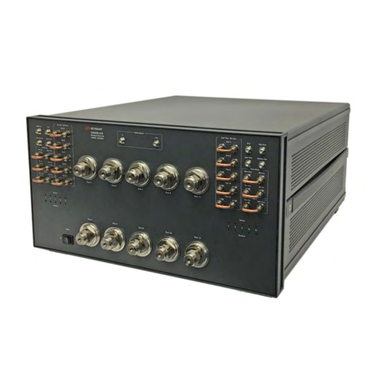
U3022BH10 Description Description The Keysight U3022BH10 is a 10-Port Multiport Test Set Extension that is designed to be configured for high power measurements in either a 14 or 24-Port network analyzer measurement system. The Keysight U3022BH10 has the following key features: •... -
Page 12: Measurement Application Notes
Mounting Kits The Test Set available cable options: • U3022BH10-1CN Front Handle Kit 1CN105A* (5063-9229) • U3022BH10-1CM Rack Mount Kit without Handles 1CM130A* (5063-9216) • U3022BH10-1CP Rack Mount Kit with Handles 1CP126A* (5063-9236) New dark color version (Keysight color palette 2015) -
Page 13: General Specifications
General Specifications General Specifications The U3022BH10 performance is based on external components such as the calibration kit and network analyzer. There are no internal adjustment in the Test Set, therefore an annual calibration is not required. A functional certificate is supplied for the U3022BH10 only. -
Page 14: Power Requirements
The mains plug shall be inserted only into a socket outlet provided with a protective earth contact. Any interruption of the protective conductor, inside or outside the instrument, is likely to make the instrument dangerous. Intentional interruption is prohibited. U3022BH10 User's and Service Guide... -
Page 15: Environmental Requirements
12.7 kg (28 lb) 22.15 cm 42.5 cm 50 cm (8.7 in) (16.7 in) (20 in) U3022BH10 14.4 kg (31.7 lb) 22.15 cm 42.5 cm 50 cm Option 129 (8.7 in) (16.7 in) (20 in) U3022BH10 User's and Service Guide... -
Page 16: Frequency Range And Maximum Power Levels
U3022BH10 Frequency Range and Maximum Power Levels The U3022BH10 frequency range is 10 MHz to 26.5 GHz. It is recommend that you do not operate near damage levels. The power levels must be 3 dB below maximum level to ensure no damage. See Table 5 below. -
Page 17: System Reflection Tracking Performance
−19 −11 −15 −21 1. PNA-X power level set to -15 dBm for the measurement of this E-Term. The Port 3 path through the U3020AH37 has a limited, 700 MHz to 18 GHz, frequency range. U3022BH10 User's and Service Guide... -
Page 18: Front And Rear Panel Features
— CPLR THRU - SRC OUT, Jumper can be removed to install the amplifiers and isolators. 5 • Port 3 – 12 — CPLR THRU - SRC OUT, Jumper can be removed to install the amplifiers and isolators. • Option 129 Ports — Noise Source Ports, In and Out. 7 U3022BH10 User's and Service Guide... -
Page 19: Test Ports - 3.5 Mm Bulkhead
Front Panel (Option 129) Option 129 Port Access Ports (odd) (Noise Source Ports) Access Ports (even) Interconnect Ports Access Access Port 2 Port 1 Test Port Active LED LEDs Test Ports Standby Switch 3 - 12 U3022BH10 User's and Service Guide... -
Page 20: Control Lines And Voltage Adjust
The front panel switch is only a standby switch and is not a LINE switch. Alternatively, an externally installed switch or circuit breaker (which is readily identifiable and is easily reached by the operator) may be used as a disconnecting device. U3022BH10 User's and Service Guide... -
Page 21: Power Cords
The use of other fuses, circuit breakers or materials is prohibited. Figure 7 Line Fuse Verify that the premise electrical voltage supply is within the range specified on the instrument. U3022BH10 User's and Service Guide... -
Page 22: System Configurations
U3022BH10 System Configurations System Configurations The Keysight U3022BH10 High Power Test Set can be configured for many applications. Included in this document are four typical configurations: System Setup, 14 Ports" on page 23 • System Setup, 14/24 Ports with U3020AH37" on page 31 •... -
Page 23: System Setup, 14-Ports
If this is the case, you will need the Lock-Link accessories shown in Table 7 below. Only interface cabling is provided with the U3022BH10 Test Set as indicated in Table 1, page 11. If you are installing the equipment in a racked system cabinet, skip this procedure and go to "Interface Cable... -
Page 24: Preparing The Test Set
Figure 10 Install Lock-Link Clips 5. Install the two rear locking feet onto the U3022BH10. Looking at the front panel, the N5242-20206 is the right foot and the N5242-20207 is the left foot. Two screws (0515-2317) are included with these rear feet. -
Page 25: Interface Cable Connection, 14-Port System
• Port 13 over Port 3 • Port 14 over Port 4 5. Connect the cable (N4011-21002) from the PNA-X Test Set I/O to the U3022BH10 Test Set I/O on the rear panel. See Figure 13 on page 6. - Page 26 System Setup, 14-Ports U3022BH10 Figure 13 RF Cable Interface Configuration Front Panel Jumpers Front Panel Jumpers N5222-20091 N5222-20091 U3022BH10 User's and Service Guide...
-
Page 27: System Operational Checks
Before beginning this procedure complete the following steps: • Stack the analyzer system for the 14-Port System. • Install the Test Set I/O cable on the U3022BH10 and PNA-X rear panels. • Install all of the RF interface cables as shown in Figure •... - Page 28 System Setup, 14-Ports U3022BH10 Figure 14 Typical Reflection Response Port 1 and 2 Figure 15 Port 1 and 2, RF Path Diagram U3022BH10 User's and Service Guide...
- Page 29 System Setup, 14-Ports U3022BH10 Figure 16 Typical Reflection Response Test Set (Odd Ports) Figure 17 Typical Reflection Response Test Set (Even Ports) U3022BH10 User's and Service Guide...
- Page 30 System Setup, 14-Ports U3022BH10 Figure 18 Test Set RF Path Diagram U3022BH10 User's and Service Guide...
-
Page 31: System Setup, 14/24 Ports With U3020Ah37
PNA-X and Test Set, with the U3020AH37 Switch Matrix, in a racked system cabinet. In this case, you will need the rack mount accessories shown in Table 9 below. Only interface cabling is provided with the U3022BH10 Test Set. The U3020AH37 provides the extra semi-rigid interface cables needed for these systems. -
Page 32: 14-Port System Setup
U3022BH10 System Setup, 14/24 Ports with U3020AH37 14-Port System Setup Figure 19 14-Port System Cable Connections U3022BH10 User's and Service Guide... - Page 33 U3022BH10 System Setup, 14/24 Ports with U3020AH37 Figure 20 14-Port System Rear Panel I/O Cable Connection N4011-21002 U3022BH10 User's and Service Guide...
-
Page 34: 24-Port System Setup
System Setup, 14/24 Ports with U3020AH37 U3022BH10 24-Port System Setup Figure 21 24-Port System Cable Connections U3022BH10 User's and Service Guide... -
Page 35: System Operational Checks
Before beginning this procedure complete the following steps: • Stack the analyzer system for the 24-Port System. • Install the two Test Set I/O cables on the U3022BH10 rear panels. • Install all of the RF interface cables (U3022-20214) as shown on the front panel. •... - Page 36 System Setup, 14/24 Ports with U3020AH37 U3022BH10 Plots and Setup Drawings Figure 22 Typical Reflection Response Port 1 Figure 23 Typical Reflection Response Port 2 U3022BH10 User's and Service Guide...
- Page 37 System Setup, 14/24 Ports with U3020AH37 U3022BH10 Reflection Response Signal Path Diagram Ports 1 and 2 Figure 24 U3022BH10 User's and Service Guide...
- Page 38 System Setup, 14/24 Ports with U3020AH37 U3022BH10 Figure 25 Typical Reflection Response, Port 3 Figure 26 Typical Reflection Response, Port 4 U3022BH10 User's and Service Guide...
- Page 39 System Setup, 14/24 Ports with U3020AH37 U3022BH10 Reflection Response Signal Path Diagram Ports 3 and 4 Figure 27 U3022BH10 User's and Service Guide...
- Page 40 System Setup, 14/24 Ports with U3020AH37 U3022BH10 Figure 28 Typical Reflection Response, Ports 5, 9, 13, 17, 21 (Test Set #1) Figure 29 Typical Reflection Response, Ports 6, 10, 14, 18, 22 (Test Set #1) U3022BH10 User's and Service Guide...
- Page 41 System Setup, 14/24 Ports with U3020AH37 U3022BH10 Reflection Response Signal Path Diagram Test Set #1 Ports Figure 30 U3022BH10 User's and Service Guide...
- Page 42 System Setup, 14/24 Ports with U3020AH37 U3022BH10 Typical Reflection Response, Ports 7, 11, 15, 19, 23 (Test Set #2) Figure 31 Typical Reflection Response, Ports 8, 12, 16, 20, 24 (Test Set #2) Figure 32 U3022BH10 User's and Service Guide...
- Page 43 System Setup, 14/24 Ports with U3020AH37 U3022BH10 Reflection Response Signal Path Diagram Test Set #2 Ports Figure 33 U3022BH10 User's and Service Guide...
-
Page 44: Controlling The System With The Pna-X
Analog Sweep, but is more accurate. Stepped Sweep is available on all PNA models. 1. On the PNA select STIMULUS > Sweep > Sweep Setup. 2. Select Stepped Sweep. 3. Set the Dwell Time to 5 μs > OK. Figure 34 PNA Sweep Setup U3022BH10 User's and Service Guide... -
Page 45: Sweep Setup For Pna-X N52Xxb Models
1. Select [Sweep] > Sweep Setup > Timing. 2. Select Timing tab. 3. Select Sweep Mode: Stepped. 4. Deselect Time: Auto Sweep Time. 5. Set Dwell Time > Apply > OK. Figure 35 Sweep Setup, N52xxB U3022BH10 User's and Service Guide... -
Page 46: Pna-X Multiport Mode
Test Set file to the PNA-X hard drive. The current version of the Test Set files are available on the web at http://na.support.keysight.com/multiport. Copy the appropriate file to c:\Program Files (x86)\Agilent\Network Analyzer\testsets directory. Figure 36 Test Set Selection U3022BH10 User's and Service Guide... -
Page 47: External Test Set Control Operation
This menu will allow the physical ports to be identified as any port number for your convenience. For example, Port 5 can be re-named Port 2. The External Test Set Control-U3022BH10 also allows control of the DUT control lines; refer to "Control Lines" on page 83. -
Page 48: Selecting An S-Parameter Measurement
S-Parameter Tab: Multiple S-Parameters can be made by selecting Trace/Chan > Trace > New Trace. -OR- (Instrument > Trace > New Trace). Use the drop-down menu and select of any of the S-Parameters. Figure 39 New S-Parameter Measurement U3022BH10 User's and Service Guide... - Page 49 In the search menu type "Multiport and Balanced." Figure 40 Selecting Balanced Measurements Receivers Tab: The S-Parameter measurements can be ratioed with selectable Denominators for each port and receiver. Refer to the standard PNA-X documentation for more information. Figure 41 Receiver Measurements U3022BH10 User's and Service Guide...
-
Page 50: N-Port Calibration With The Pna-X
PNA-X. Measurement errors can be a result of firmware algorithms. Consult with Keysight Service or firmware web page for the latest PNA-X Option 551 firmware revisions and history. http://na.support.keysight.com/pna/firmware/firmware.html. Figure 42 ECal Characterization U3022BH10 User's and Service Guide... - Page 51 If using an ECal module, connect the ECal to an available PNA-X USB port and select Use Electronic Calibration (ECal) > Next -OR- (Response > Cal > Other Cals... > ECal...). Figure 44 Begin Calibration U3022BH10 User's and Service Guide...
- Page 52 If measurement errors occur, ensure the newest version of firmware is installed on the PNA. Measurement errors can be a result of firmware algorithms. Consult with Keysight Service or firmware web page for the latest PNA Option 551 firmware revisions and history: http://na.support.keysight.com/pna/firmware/firmware.html. U3022BH10 User's and Service Guide...
-
Page 53: Interface Control Mode
• Control data is sent in the following order and this order cannot be changed: Refer to the PNA Help menu. 1. GPIB Interface 2. Material Handler Interface 3. Test Set Interface 4. Dwell Time U3022BH10 User's and Service Guide... -
Page 54: How To Access Interface Control Mode
The PNA-X Series Network Analyzer includes the Interface Control application and rear panel connection. Information regarding this application can be found in the PNA-X Help menu, Interface Control. The application is shown below. Figure 46 Interface Control Mode U3022BH10 User's and Service Guide... -
Page 55: Using Interface Control Mode
The front panel Enter key can be used to insert a new line into the field. The quantity of Test Set I/O entries that can be entered is limited by the available memory of the PNA-X. Address and Data example: (addr.data): 16.1 32.2 U3022BH10 User's and Service Guide... - Page 56 Word Pad. Applies the settings and closes the dialog box. Cancel: Does not apply changes that were made and closes the dialog box. Help: Provides additional information for using the interface control application. U3022BH10 User's and Service Guide...
-
Page 57: Scpi Control Mode
The user is required to manually input address and data using the Command Processor Console in the PNA-X Help menu. • Command Processor settings can not be saved or recalled. • Address and data can be written from the Command Processor. U3022BH10 User's and Service Guide... -
Page 58: How To Access The Command Processor
(System > System Setup > Remote Interface > SCPI Monitor Input > Show SCPI Parser Console). 2. Check the SCPI Command Processor Console box. Command Console for 'A' Model Analyzers Figure 48 Command Console for 'B' Model Analyzers Figure 49 U3022BH10 User's and Service Guide... -
Page 59: Scpi Command Processor Console
This second command feeds the newly created measurement named “ch1_S10_10” to trace 2 on the PNA-X so that it will be displayed on the PNA-X screen. DISP:WIND1:TRAC2:FEED 'ch1_S10_10' NOTE: Here are syntax format examples for single digit S-parameters: ‘ch1_S99’ ‘ch1_S22’ ‘ch1_S9_10’ ‘ch1_S10_9’ U3022BH10 User's and Service Guide... - Page 60 Address and Data values are separated by a comma. Commands should be separated by a new line, or carriage return. For example: CONT:EXT:TEST:DATA <address>,<data> CONT:EXT:TEST:DATA 0,0 Example: CONT:EXT:TEST:DATA 0,0 Method 2 - Using Test Set Address and Data Values Figure 51 U3022BH10 User's and Service Guide...
-
Page 61: Option 129 External Source Path
U3022BH10 Option 129 External Source Path The U3022BH10 with Option 129 allows an external ECal module, or noise source, to be switched into the Source path of Ports 1, 3, 5, 9, or 11. Only one port can be the active source. The front panel EXT NOISE SOURCE IN is... -
Page 62: Setting Option 129 Source Path
Noise Source Port 5 0.11 Noise Source Port 7 0.12 Noise Source Port 9 0.13 Noise Source Port 11 An 8 is added to the Data Value to activate the Option 129 switch, as indicated in Table U3022BH10 User's and Service Guide... -
Page 63: High Power Measurements
When using high power configurations an attenuator must be placed in the receiver path, and the couplers and isolators must be installed in the source path or damage to the PNA-X, or the U3022BH10 Test Set, will occur. Refer “Frequency Range and Maximum Power Levels” on page Getting Started A power meter is required for the following procedure. -
Page 64: Measuring Booster Amplifier Gain
Table Figure 54, and Figure 6. Turn On the PNA-X and U3022BH10 Test Set. 7. Select multiport mode. Refer to “Controlling the System with the PNA-X” page 8. Select trace S11 if you are using Port 1 or Odd Ports SRC Out. If you are using another port as the source port, set Sxx to the port desired. - Page 65 A IN Port 3 SOURCE OUT CPLR THRU Odd Ports RCVR IN RCVR OUT SRC IN SRC OUT Port 1 CPLR THRU SRC OUT Coupler Booster Amplifier Coupler Coupler Main Output 20 dB INPUT OUTPUT U3022BH10 User's and Service Guide...
- Page 66 CPLR THRU SRC OUT Coupler Booster Amplifier 20 dB Coupler Coupler Main Input Output Output Figure 56 Measuring the Booster Amplifier Gain Power Meter Coupler 20 dB Coupler Coupler Main Output Booster Amplifier OUTPUT INPUT U3022BH10 User's and Service Guide...
-
Page 67: Setting The Power Level At The Output Of The Dut
Save this state to recall the power level for the Input power level to the DUT. The power level should not be above the level that was determined in step 13 above. U3022BH10 User's and Service Guide... -
Page 68: Selecting Ref Attenuator Value
RCVR REF IN). 7. Turn Off the booster amplifier and connect the external coupler ARM to the REF INPUT (RCVR R1 IN or RCVR R2 IN). Refer to Figure 57 Figure 58 page U3022BH10 User's and Service Guide... -
Page 69: Selecting Rcvr A And B Path Attenuators
RCVR A/B IN). 16. Connect the attenuator outputs to receiver A IN and B IN. If you are using Ports 13 or 14, connect the same value attenuators from RCVR OUT to RCVR C/D IN. U3022BH10 User's and Service Guide... - Page 70 Booster Amplifier OUTPUT INPUT Isolator Figure 58 20 Watt High Power Configuration REF Attenuator Coupler 20 dB RCVR A Attenuator Coupler Coupler Main Output RCVR A Attenuator Fix Attenuator Fix Attenuator Booster Amplifier OUTPUT INPUT U3022BH10 User's and Service Guide...
- Page 71 CPLR ARM SRC IN SRC OUT SOURCE OUT CPLR THRU CPLR THRU SOURCE OUT SOURCE OUT CPLR THRU CPLR THRU SOURCE OUT SRC OUT SRC IN CPLR ARM B IN RCVR IN RCVR OUT REF ATTN U3022BH10 User's and Service Guide...
- Page 72 A IN CPLR ARM SRC IN SRC OUT SOURCE OUT CPLR THRU CPLR THRU SOURCE OUT SOURCE OUT CPLR THRU CPLR THRU SOURCE OUT SRC OUT SRC IN CPLR ARM B IN RCVR IN RCVR OUT U3022BH10 User's and Service Guide...
-
Page 73: Calibrating The System And Measuring The Dut
The isolators placement is important to ensure that the signal is attenuated into the U3022BH10 SRC OUT isolator connections for Port 1 and Port 2. The reverse attenuation or isolation factor of the isolator should be 20 dB or greater. - Page 74 • The value of attenuation added to receiver A - D. • The R channel reference level supplied from the Test Set. • The source power loss due to the installed isolators. U3022BH10 User's and Service Guide...
-
Page 75: Address And Data Values
Control Mode. Select Trace/Chan > Channel > Hardware Setup > Interface Control -OR- (Instrument > Setup > Internal Hardware > Interface Control...) in the drop-down menu and select Enable Interface Control. For further information, refer to "Interface Control Mode" on page U3022BH10 User's and Service Guide... - Page 76 Data Ports Ports Ports 13 and 14 are not connected to the Test Set, therefore do not require address data values. Table 14 24-Port System Address and Data Values (x2 U3022BH10) Address Source Ports Receiver Ports Test Set #1 (Top):...
- Page 77 U3022BH10 Address and Data Values Figure 61 Example 1, Test Set Signal Path (STD) S-Parameter measurements are not possible in this example. U3022BH10 User's and Service Guide...
-
Page 78: Address And Data Values For Option 129
Source Port 3 = address 0, data 9, and Receiver Port 7 = address 0, data 48. The data values are added together, for an entry of 0.57. For more information, refer to the PNA-X Help menu. U3022BH10 User's and Service Guide... - Page 79 U3022BH10 Address and Data Values Example 3 U3022BH10 Option 129 Block Diagram Figure 62 U3022BH10 User's and Service Guide...
- Page 80 U3022BH10 Address and Data Values Figure 63 Example 4 U3022BH10 Option 129 Block Diagram S-Parameter measurements are not possible in this example. U3022BH10 User's and Service Guide...
- Page 81 Selects Noise Source IN and OUT paths and Receiver for Port 9 (S99) Selects Noise Source IN and OUT paths and Receiver for Port 11 (S1111) Refer to "Test Set and System Block Diagrams" starting on page 103 for in-depth RF path information. U3022BH10 User's and Service Guide...
-
Page 82: Setting The Dut Control Lines With Address And Data Values
Another method that can be used to change the logic state of these control lines is explained in "External Test Set Control Operation" on page Only the top Test Set control lines operate in a 24-Port system. U3022BH10 User's and Service Guide... -
Page 83: Control Lines
Max Output Line Current 100 mA (each line) Control Line DC resistance < 10 Ω (each line) Voltage Range: Positive Input 0 to +5 V Negative Input –5 to 0 V Internal Variable Voltage +2 to +5 V U3022BH10 User's and Service Guide... - Page 84 Internal voltage output, adjusted with the trimmer on the rear panel. Positive Input Connection for internal (pin 12) or external positive voltage supply. Negative Input Connection for ground (pin 15) or external negative voltage supply. Ground terminal U3022BH10 User's and Service Guide...
-
Page 85: Internal Voltage Supply Configuration
You may only connect pin 12–13, and pin 14–15, damage may result if any other paths are short-circuited. Figure 65 Internal DC Power Configuration (Rear Panel View) Line 1 Line 2 (Rear Panel View) DUT (Only required Lines) Line 8 2 to 5 Vdc TEST SET U3022BH10 User's and Service Guide... -
Page 86: External Voltage Supply Configuration
Test Set to the DUT and External DC Power Supply Line 1 Line 2 (Rear Panel View) DUT (Only required Lines) DC Power Supply Line 8 + Gnd 2 to 5 Vdc Positive: 0 to 5 Vdc Negative: 5 to 0 Vdc TEST SET U3022BH10 User's and Service Guide... -
Page 87: Operational Check
4. Ensure that the standard jumpers are installed. Verification Limits Specifications for the U3022BH10 Multiport Test Set are typical. System performance for the PNA-X and Test Set are only characteristic and intended as non warranted information. A functional certificate is provided for the U3022BH10 only. -
Page 88: Equipment Required
If you suspect that your 14-Port configuration is not operating properly, ensure that all front RF jumper interface cables are correctly attached and measurement stable when flexed lightly. Equipment Required The Keysight U3022BH10 requires that the user be familiar with the equipment listed. Table 22 Equipment List Description 3.5 mm ECal Module 10 MHz - 26.5 GHz (Option 00F or M0F) or... -
Page 89: Reflection Tracking Check Procedure
Verification Procedure," step 12.Allow the ECal module, Test Set and PNA-X to warm up for a minimum of 30 minutes. 1. Set to [-15 dBm] for Port 3 measurement (24-Port system) to prevent damage to ECal module. U3022BH10 User's and Service Guide... -
Page 90: N5241/2A/B 1-Port Calibration And Verification Procedure
If you do not have a key board, select Save As User Calset > Edit Name and save as 999.x. X is the port number you are calibrating. See Figure 69 below. Use the numeric keypad on the PNA-X front panel to enter "999.1." Figure 69 Calibration Complete U3022BH10 User's and Service Guide... - Page 91 7. Press Trace/Chan > Trace > Delete Trace. There should be no traces on the PNA-X display; delete traces that are listed, then select OK. 8. To launch the Cal Set Viewer toolbar. Select Response > Cal > Manage Cals > Cal Set Viewer. Figure 71 Calibration, Cal Set Viewer U3022BH10 User's and Service Guide...
- Page 92 11.Repeat step 9 step 10 for the Cal Sets that you have saved. Figure 72 PNA-X Setting the Test Limits Figure 73 Reflection Tracking Trace Error Term Enable 999.1 Limit Table U3022BH10 User's and Service Guide...
- Page 93 13. Repeat step 9 step 12 for Cal Sets "999.1" thru "999.12". Figure 74 Example: 14-Port System Reflection Tracking Trace (Port 1) Figure 75 Example: 14-Port System Reflection Tracking Trace (Port 11) U3022BH10 User's and Service Guide...
-
Page 94: Verifying Operational Check Failures
"System Operational Checks" given on page 27. For the 24-Port system configuration, you can use a similar concept. 2. If more details are needed for troubleshooting the U3022BH10, refer to the "Service Information" section on page U3022BH10 User's and Service Guide... -
Page 95: Service Information
These servicing instructions are for use by qualified personnel only. To avoid electrical shock, do not perform any servicing unless you are qualified to do so. Replaceable Parts The following replaceable parts are available from Keysight Technologies "Find-A-Part" system on the web at www.keysight.com/my/faces/fapHomePage.jspx. Table 23... - Page 96 Front Panel LED Board (programmed) N5261-60005 Test Set Control Board (programmed) N5261-60006 Screw-Pan Head Machine with thread patch, 0515-2317 Torx-T15 M3.5 with 0.6 thread, 12 mm-LG Port Label Page U3024-80001 U3022BH10 User’s and Service Guide U3022-90010 U3022BH10 User's and Service Guide...
-
Page 97: Servicing Diagrams
U3022BH10 Service Information Servicing Diagrams Figure 76 Test Set Electrical Diagram U3022BH10 User's and Service Guide... - Page 98 U3022BH10 Service Information Figure 77 Top View (STD) DUT Co ntrol Bd Test Set Switch Interface Bd Control Bd (top Bd) (bottom Bd) Couplers (x10) U3022BH10 User's and Service Guide...
- Page 99 Service Information U3022BH10 Figure 78 Top View (Option 129) DUT Co ntrol Bd Test Set Control Bd Switch (bottom Bd) Interface Bd (top Bd) Couplers (x10) U3022BH10 User's and Service Guide...
- Page 100 Service Information U3022BH10 Figure 79 Bottom View (STD) Line Module Power Supply Fuse (x2) Coupler (x10) U3022BH10 User's and Service Guide...
- Page 101 U3022BH10 Service Information Figure 80 Bottom View (Option 129) Power Supply Line Module Fuses (x2) Couplers (x10) U3022BH10 User's and Service Guide...
-
Page 102: Theory Of Operation
U3022BH10 Theory of Operation Theory of Operation The following is a description of the operation of the U3022BH10. Reference the U3022BH10 block diagrams, starting on page 103. This section assumes the user has a general understanding of couplers, switches, and network analyzers. -
Page 103: Test Set And System Block Diagrams
Test Set and System Block Diagrams U3022BH10 Test Set and System Block Diagrams Figure 81 Test Set RF Diagram (STD) U3022BH10 User's and Service Guide... - Page 104 U3022BH10 Test Set and System Block Diagrams Figure 82 Test Set RF Diagram (Option 129) U3022BH10 User's and Service Guide...
- Page 105 U3022BH10 Test Set and System Block Diagrams Figure 83 14-Port System (Option 129) U3022BH10 User's and Service Guide...
- Page 106 Test Set and System Block Diagrams U3022BH10 Figure 84 14-Port System Configuration (with U3020AH37) U3022BH10 User's and Service Guide...
- Page 107 U3022BH10 Test Set and System Block Diagrams Figure 85 24-Port System Configuration U3022BH10 User's and Service Guide...
- Page 108 Test Set and System Block Diagrams U3022BH10 Figure 86 24-Port System Configuration (U3020BH10 x2) U3022BH10 User's and Service Guide...
-
Page 109: Troubleshooting The Test Set
Troubleshooting the Test Set Troubleshooting the Test Set If the U3022BH10 is not operating properly, use the following procedures to isolate and repair the type of failure encountered. It is recommended that a qualified service technician perform the following procedures. -
Page 110: Rf Switching Malfunctions
+21 Vdc voltage from the switch driver board. 1. The PNA and the Test Set need to be connected together with the Test Set I/O cable (8120-6818). 2. Verify the Test Set I/O cable is installed correctly. See Figure 20 on page U3022BH10 User's and Service Guide... -
Page 111: Source And Receiver Path Test
• Confirm the frequency range is set to 10 MHz to 26.5 GHz. • Connect RF Flex cables to PNA Ports 1 and 2. Connect the cables together with a 3.5 mm adapter. • Configure the PNA-X to measure S21 and normalize the response trace. U3022BH10 User's and Service Guide... -
Page 112: Cable Connections
Source Figure 88 RCVR A/B IN to Ports 3-12 Receiver Figure 89 Source IN to CPLR THRU Source Figure 90 A/B IN to CPLR ARM Receiver Figure 90 Pass Thru Access Ports Source/Receiver Figure 91 U3022BH10 User's and Service Guide... -
Page 113: Source Signal Path Insertion Loss Test
Source OUT to Port 10 16.4 P10 CPLR, S20 Source OUT to Port 12 P12 CPLR, S20 16.5 Use the Source IN port associated with this group of test ports. Figure 88 Source OUT to Ports 3-12 Path Response U3022BH10 User's and Service Guide... -
Page 114: Receiver Signal Path Insertion Loss Test
16.4 P10 CPLR, S21 B IN to Port 12 P12 CPLR, S21 16.5 Use the Source IN port associated with this group of test ports. Figure 89 RCVR A/B IN to Ports 3-12 Path Response U3022BH10 User's and Service Guide... - Page 115 RF Path Description Path Components (Typical) Group <address>.<data> Odd Ports A IN to CPLR ARM Figure 90 Even Ports B IN to CPLR ARM 16.0 Use the Source IN port associated with this group of test ports. U3022BH10 User's and Service Guide...
-
Page 116: Pass Thru Access Ports Signal Path Insertion Loss Test
CPLR ARM to CPLR ARM Figure 91 Internal Cable CPLR THRU to CPLR THRU Source IN to Source IN Use the Source IN port associated with this group of test ports. Figure 91 Pass Thru Access Ports Path Response U3022BH10 User's and Service Guide... -
Page 117: Safety And Regulatory Information
Declaration of Conformity A copy of the Declaration of Conformity is available upon request, or a copy is available on the Keysight Technologies web site at: http://regulations.about.keysight.com/DoC/default.htm Statement of Compliance This instrument has been designed and tested in accordance with CAN/CSA 22.2 No. -
Page 118: Before Applying Power
(outside the cabinet) must be less than the maximum operating temperature of the instrument by 4 °C for every 100 watts dissipated in the cabinet. If the total power dissipated in the cabinet is greater than 800 watts, forced convection must be used. U3022BH10 User's and Service Guide... -
Page 119: Servicing
Allow all residual alcohol moisture to evaporate, and fumes to dissipate prior to energizing the instrument. To prevent electrical shock, disconnect the Keysight Technologies U3022BH10 from mains electrical supply before cleaning. Use a dry cloth or one slightly dampened with water to clean the external case parts. -
Page 120: Electrostatic Discharge Protection
2. While wearing a grounded wrist strap, grasp the outer shell of the cable connector. 3. Connect the other end of the cable to the test port and remove the short from the cable. Figure 92 ESD Protection Setup U3022BH10 User's and Service Guide... -
Page 121: Instrument Markings
Universal recycling symbol. This symbol indicates compliance with the China standard GB 18455-2001 as required by the China RoHS regulations for paper/fiberboard packaging. South Korean Certification (KC) mark. It includes the marking’s identifier code in the format shown. R-R-Kst- ZZZZZZZ U3022BH10 User's and Service Guide... -
Page 122: Battery Collection
Regulatory Information Battery Collection Do not throw batteries away but collect as small chemical waste, or in accordance with your country’s requirements. You may return the battery to Keysight Technologies for disposal. Refer to "Contacting Keysight" on page 123 for assistance. -
Page 123: Keysight Support, Services, And Assistance
Keysight for repair. If you wish to send your instrument to Keysight Technologies for service or repair: • To improve turn-around time, return your instrument along with your PNA-X and cables to Keysight so that we may verify the operation of the complete system. - Page 124 This information is subject to change without notice. © Keysight Technologies 2017, 2019 Print Date: March 2019 Supersedes: March 2017 www.keysight.com...
Need help?
Do you have a question about the U3022BH10 and is the answer not in the manual?
Questions and answers