Table of Contents
Advertisement
Quick Links
Advertisement
Table of Contents

Related Manuals for Keysight Technologies U3020AD01


Summary of Contents for Keysight Technologies U3020AD01
- Page 1 Keysight Technologies U3020AD01 User’s and Service Guide...
- Page 2 KEYSIGHT SHALL NOT BE LIABLE is embodied in its End User License Keysight Technologies, Inc. as FOR ERRORS OR FOR INCIDENTAL Agreement (EULA), a copy of which governed by United States and...
-
Page 3: Table Of Contents
Table of Contents U3020AD01 Introduction ............. . . - Page 4 Table of Contents Adding Instruments to the GPIB Configuration ......Changing the GPIB Address ......... LAN and GPIB Interface Configuration Commands .
- Page 5 U3020AD01...
-
Page 6: Introduction
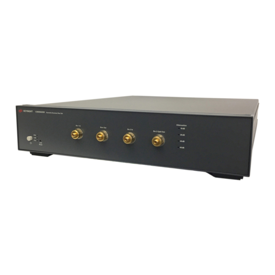
U3020AD01 Introduction Introd uction This document describes how to use and service the Keysight U3020AD01 Dynamic Accuracy Test Set. Figure 1 U3020AD01 Dynamic Accuracy Test Set Keysight U3020AD01 User's and Service Guide... -
Page 7: Description
Test Set in their production and service processes. The U3020AD01 Test Set can only be controlled via the rear panel GPIB or LAN interfaces. When using the Connection Expert utility program, available on the PNA-X platform and other computer platforms, the program may identify the Test Set as "L449XA"... -
Page 8: General Performance
Test Set. The Test Set is not specified for overall system performance. A functional certificate is supplied for the U3020AD01. There are no internal adjustment in the U3020AD01, therefore an annual calibration is not required. This product has an autoranging line voltage input. Be sure the supply voltage is within the specified range. -
Page 9: Environmental Requirements
PNA-X and Test Set to be maintained within ± 1 °C of the ambient temperature at calibration. Dimensions and Space Requirements Standard installation of the U3020AD01 and PNA includes configuration and installation on a customer provided lab bench or table top of adequate size and strength. -
Page 10: Maximum Power Levels And Performance Characteristics
< -45 RCVR OUT to SRC2 IN SRC1 IN to SRC2 IN 1.8 - 2.2 < -70 Port Match: All Ports < -12 1.8 - 2.2 1. Unconnected ports must be terminated in 50 Ohms. Keysight U3020AD01 User's and Service Guide... -
Page 11: Front And Rear Panel Features
• SRC 2 CPLD OUT (Coupler Out) Instrument State LEDs When the power is applied to the U3020AD01, the instrument enters its power-on sequence which requires several seconds to complete. The LEDs provide information on the state of the instrument during power-on and during upgrades of the instrument firmware. - Page 12 Instrument programming error or self-test error. Green Error queue is read using SYSTem:ERRor? Green ATTN Instrument identification. Activated from instrument Green (Flashing) Web interface: Green ON: Turn on Front Panel Interface Indicator OFF: Turn off Front Panel Interface Indicator Keysight U3020AD01 User's and Service Guide...
-
Page 13: Gpib Connector
The mains plug shall only be inserted in a socket outlet provided with a protective earth contact. Any interruption of the protective cond uctor inside or outside of the product is likely to make the product dangerous. Intentional interruption is prohibited. Keysight U3020AD01 User's and Service Guide... -
Page 14: Controlling The Test Set
Controlling the Test Set Controlling the Test Set The Keysight U3020AD01 is a “slave” instrument and requires a controller to be used to control the Test Set. There are two methods that can be used to control the Test Set: •... - Page 15 20 dB Attenuator Bank On programmable attenuator ATT1_CARD3 40 dB Attenuator Bank 1 On sections. ATT1_CARD4 40 dB Attenuator Bank 2 On LED_ALL All LEDs On Diagnostic checks of the attenuator LEDs. LED_OFF All LEDs Off Keysight U3020AD01 User's and Service Guide...
-
Page 16: Operational Verification
4. Set PNA-X IFBW: 100 Hz, Number of points: 401 5. PNA-X frequency range: 1 to 4 GHz. 6. Set the PNA-X to Measure S21, Scale to 10 dB/Div. 7. Set PNA-X markers to 2.0 and 3.5 GHz. Figure 4 Equipment Setup Keysight U3020AD01 User's and Service Guide... -
Page 17: Measurement Setup
- Check this GPIB Address - Auto ID this Instrument - OK Information related to the L449XA or U3020A will be displayed on the right side of the window. Figure 6 Connection Expert, Connected Instruments Keysight U3020AD01 User's and Service Guide... - Page 18 10. To begin the testing, set the path attenuator to 0 dB and type the following command as shown in the Command field: ROUT:SEQ:TRIG ATT1_00 [Send Command] All LED indicators on the Test Set should be OFF. Keysight U3020AD01 User's and Service Guide...
-
Page 19: Measurement Sequence, Test Instructions
RCVR OUT to SRC2 CPLD OUT RCVR OUT to SRC1 IN ATT1_00 ≤ -45 RCVR OUT to SRC2 IN SRC1 IN to SRC2 IN ≤ -70 1. Terminate unconnected ports with a 50 Ohm Load. Keysight U3020AD01 User's and Service Guide... -
Page 20: Service Information
Service Information Service Information There are many other repair and calibration options available from the Keysight Technologies support organization. The options cover a range of service agreements with varying response times. Contact Keysight for additional information on available service agreements for this product. -
Page 21: Replacement Parts
Attenuator LED Interface Board (PCB1) U3020-63114 Distribution Card (PCB3) Y1153-66511 Before replacing an assembly or board, inspect the assembly for obvious, easily repaired defects such as bent pins on ICs or cold solder joints. Keysight U3020AD01 User's and Service Guide... - Page 22 U3020AD01 Service Information Figure 8 U3020AD01 (top view) Controller Module PCB1 34945EXT SW/ATTN Driver Module Isolator (x4) PCB3 PCB2 Step Power Divider Coupler Attenuator Keysight U3020AD01 User's and Service Guide...
-
Page 23: Theory Of Operation
The Test Set consists of four main non-RF components: a controller module, a 39495EXT module, distribution board for programmable step attenuator, and front panel LED indicator circuits. Figure 9 Test Set Block Diagram Keysight U3020AD01 User's and Service Guide... -
Page 24: Controller Module
LED Indicator Board (PCB2) This board provides an LED indication of the step attenuator value setting in the Test Set. The LED indicator board is driven by the digital port of the controller module. Keysight U3020AD01 User's and Service Guide... -
Page 25: Troubleshooting
Measure the DC voltage between the red and black wires. The red wire should measure approximately +12 Vdc. d. If any voltages are not present, the controller module power supply will need to be replaced. Keysight U3020AD01 User's and Service Guide... -
Page 26: Rf Switch Not Switching
Port to be selected, it is possible that the instrument Power On preset set has been corrupted. c. Contact Keysight Technologies for support in recovering this preset set. d. If no audible sound is heard, remove the top cover of the instrument. -
Page 27: Instrument Settings
Configuring the LAN Interface 1. Connect the Test Set to the PC. 2. Turn On the Test Set. 3. Select IO Control icon > Agilent Connection Expert from the application window. Figure 10 Keysight Connection Expert Keysight U3020AD01 User's and Service Guide... -
Page 28: Locating The Instrument
3. Select the desired instruments from the list and click OK. Communication paths to the instruments are verified and the instruments are added to the configured interface. Figure 12 Add ing Instruments Keysight U3020AD01 User's and Service Guide... -
Page 29: Configuring The Gpib Interface
1. From the Keysight Connection Expert application window, highlight the instrument that's address was changed and click Change Properties in the Configurable Properties application window, change the address to the new address setting and select OK. Keysight U3020AD01 User's and Service Guide... -
Page 30: Lan And Gpib Interface Configuration Commands
You can also query the U3020A for the IP address it was assigned to. Example: The following command sets the IP address: SYST:COMM:LAN:IPAD 169.254.149.35 The following query returns the IP address currently being used by the instrument (quotes are also returned): SYST:COMM:LAN:IPAD? Typical response: "169.254.149.35" Keysight U3020AD01 User's and Service Guide... -
Page 31: Auto-Ip Command
If you change the DHCP setting, you must cycle power on the U3020A to activate the new setting. Example: The following command disables DHCP: SYST:COMM:LAN:DHCP OFF The following query returns the current DHCP setting: SYST:COMM:LAN:DHCP? Typical Response: 0 Keysight U3020AD01 User's and Service Guide... -
Page 32: Dns Command
If you change the Domain Name, you must cycle power on the U3020A to activate the new address. Example: The following command defines the Domain Name: SYST:COMM:LAN:DOM www.keysight.com The following query returns the Domain Name currently being used by the instrument: SYST:COMM:LAN:DOM? Typical response: www.keysight.com Keysight U3020AD01 User's and Service Guide... -
Page 33: Gateway Address Command
Example The following command defines a Host Name: SYST:COMM:LAN:HOST "LAB1-U3020A" The following query returns the Host Name currently being used by the instrument (the quotes are also returned): SYST:COMM:LAN:HOST? Typical Response: "LAB1-U3020A" Keysight U3020AD01 User's and Service Guide... -
Page 34: Gpib Configuration Command
The following command sets the GPIB address to 9: SYST:COMM:GPIB:ADDR 9 The following query returns the current GPIB address: SYST:COMM:GPIB:ADDR? Typical Response: 9 For a complete list of SCPI commands, refer to the Keysight L449xA RF Switch Platform User’s Guide (L4490-90001) Keysight U3020AD01 User's and Service Guide... -
Page 35: Safety Information
If flammable cleaning materials are used, the material shall not be stored, or left open in the area of the equipment. Adequate ventilation shall be assured to prevent the combustion of fumes, or vapors. Keysight U3020AD01 User's and Service Guide... -
Page 36: Before Applying Power
(outside the cabinet) must be less than the maximum operating temperature of the instrument by 4 °C for every 100 watts dissipated in the cabinet. If the total power dissipated in the cabinet is greater than 800 watts, forced convection must be used. Keysight U3020AD01 User's and Service Guide... - Page 37 The front panel switch is only a stand by switch and is not a LINE switch (d isconnecting device). Keysight U3020AD01 User's and Service Guide...
-
Page 38: Instrument Markings
Forty years is the expected useful life of the product. This symbol on all primary and secondary packaging indicates compliance to China standard GB 18455-2001. South Korean Certification (KC) mark; includes the marking's identifier code which follows the format: MSIP-REM-YYY-ZZZZZZZZZZZZZZ. Keysight U3020AD01 User's and Service Guide... -
Page 39: Regulatory Information
Battery Do not throw batteries away but collect as small chemical waste, or in accordance with your country’s “Contacting requirements. You may return the battery to Keysight Technologies for disposal. Refer to Keysight” on page 35 for assistance. Complies with the essential requirements of the European EMC Directive as well as current editions of the following standards (dates editions are cited in the Declaration of Conformity): •... -
Page 40: Keysight Support, Services, And Assistance
Keysight for repair. If you wish to send your instrument to Keysight Technologies for service or repair: • Include a complete description of the service requested or of the failure and a description of any failed test and any error message. - Page 41 Keysight U3020AD01 User's and Service Guide...
- Page 42 This information is subject to change without notice. © Keysight Technologies 2011-2017, 2019 Print Date: December 2019 Supersedes: August 2019 www.keysight.com...
Need help?
Do you have a question about the U3020AD01 and is the answer not in the manual?
Questions and answers