Table of Contents
Advertisement
Quick Links
Advertisement
Table of Contents

Related Manuals for Keysight Technologies U3042AM08


Summary of Contents for Keysight Technologies U3042AM08
- Page 1 Keysight Technologies U3042AM08 Multiport Test Set Extension Notice: This document contains references to Agilent. Please note that Agilent’s Test and Measurement business has become Keysight Technologies. For more information, go to www.keysight.com. User's and Service Guide...
- Page 2 DOCUMENT THAT CONFLICT WITH government requirements THESE TERMS, THE WARRANTY beyond those set forth in the © Keysight Technologies, Inc. 2019 TERMS IN THE SEPARATE EULA shall apply, except to the AGREEMENT WILL CONTROL. No part of this manual may be...
-
Page 3: Table Of Contents
Table of Contents U3042AM08 Introduction ...............8 Description. - Page 4 Table of Contents Sweep Setup for PNA-X N524xB Models......... . 37 Multiport Mode (Option 551) .
- Page 5 Table of Contents 1-Port Calibration and Verification Procedure ........68 Option 129 Operational Check .
- Page 6 Table of Contents Connector Care and Cleaning Precautions ........95 Regulatory Information .
- Page 7 U3042AM08...
-
Page 8: Introduction
U3042AM08 Introduction Introd uction This document describes how to use and service the U3042AM08 Multiport Test Set with the Keysight 4-Port PNA, PNA-L and PNA-X for a 12-Port network analyzer solution. Figure 1 4-Port PNA-L with U3042M08 Figure 2 4-Port PNA or PNA-X with U3042M08... -
Page 9: Description
U3042AM08 Description Description The U3042AM08 is a Multiport Test Set Extension designed to be configured in a 8 Port network analyzer measurement systems. The U3042AM08 has the following key features: • 8 Test Ports (3.5mm Male connectors) • Low Loss mechanical RF switching •... -
Page 10: Network Analyzer Requirements
The U3042AM08 Option 129 test set requires that the analyzer also have option H29 or 029 installed in order to use the test set for noise figure measurements. -
Page 11: Available Options
These part numbers are for the previous Agilent Palette 2000 (beige) color format. Network Analyzer Interface Kit Options The U3042AM08 will require one of the following kits to interface the test set with your network analyzer. The Interface kit model option includes the hard ware... -
Page 12: General Specifications
The mains plug shall be only be inserted in a socket outlet provided with a protective earth contact. Any interruption of the protective cond uctor inside or outside of the instrument, is likely to make the prod uct dangerous. Intentional interruption is prohibited. Keysight U3042AM08 User's and Service Guide... -
Page 13: Environmental Requirements
General Specifications Environmental Requirements Refer to the PNA, PNA-L and PNA-X standard documentation for environmental specifications. The U3042AM08 complies with all applicable safety and regulatory requirements for the intended location of use. • Pressure Altitude (Operation) 3,000 meters (~10,000 feet) •... -
Page 14: Maximum And Recommended Power Levels
Refer to your analyzer’s specifications to determine the maximum input power levels for the access and test ports, or to optimize the power levels in the receivers. NOTE Damage and maximum levels are not necessarily the optimum level. Keysight U3042AM08 User's and Service Guide... -
Page 15: Typical Reflection Tracking
Performance for the test set is typical. System performance for the analyzer and Test Set are only characteristic and are intended as non-warranted information. A functional certificate is provided for the U3042AM08 only. NOTE Typical performance is based on 1 to 2 units, see... -
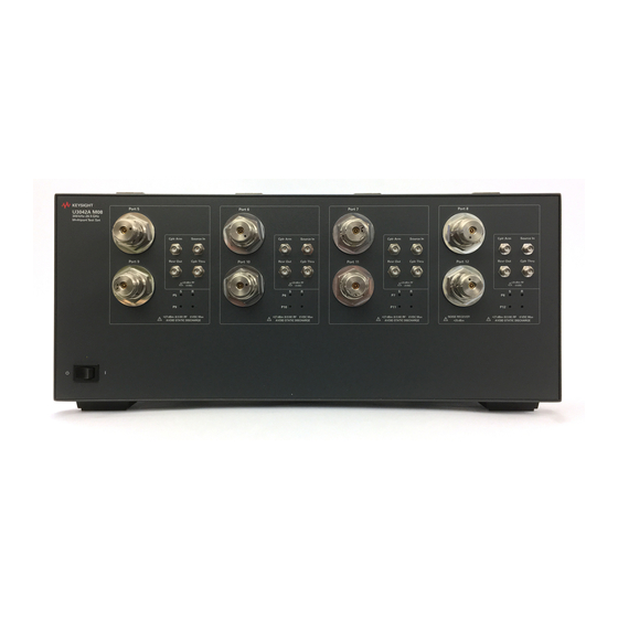
Page 16: Front And Rear Panel Features
Test Ports 5 - 12 Access Ports Coupler Arm Source In Coupler Thru Receiver Out Active Standby Switch Port Status LEDs (4 sets) Figure 4 Option 129 Front Panel Opt 129 SOURCE IN Opt 129 SOURCE OUT Active Keysight U3042AM08 User's and Service Guide... - Page 17 Test Set connected to the PNA-X will never have an "ON" Active LED. Instead, the last Test Set in the I/O chain will be the Test Set showing the "Active LED" status for all. Keysight U3042AM08 User's and Service Guide...
- Page 18 The Pass Through Interface is used to connection to another Test Set. Interface Test Set Interface The Test Set Interface connector is used to send address and data to the Test Set from the analyzer. Keysight U3042AM08 User's and Service Guide...
- Page 19 For continued protection against fire hazard replace line fuse only with same type and rating. The use of other fuses or material is prohibited. Figure 6 Line Fuse CAUTION Verify that the premise electrical voltage supply is within the range specified on the instrument. Keysight U3042AM08 User's and Service Guide...
-
Page 20: System Setup With N5230C And N5232A/B
2. Remove the feet from the bottom of the analyzer. 3. Remove the 2 lower standoffs and screws (0515-1619) from the rear panel on the analyzer. Figure 7 Rear Bottom Feet Standoffs (x2) Feet (x4) Keysight U3042AM08 User's and Service Guide... - Page 21 5. Remove the top two standoffs and screws (0515-1619) from the rear panel on the Test Set. 6. Install the top left and right rear locking feet from the kit (5063-9253) using screws (0515-1244). Figure 9 Rear Locking Feet Keysight U3042AM08 User's and Service Guide...
- Page 22 The lock-feet kit (U3021-60001) includes the analyzer and Test Set lock-feet. Refer “Contacting Keysight” on page 99 for ordering information. • PNA - 5023-0132 (Kit includes locking feet and screws) • Test Set - 5063-9253 (Kit includes lock links, locking feet and screws) Keysight U3042AM08 User's and Service Guide...
-
Page 23: Pna-L Rf Interface Cable Connections
PNA-L Interface Cable Connection (U3021-60045) RF Cables From PNA-L To Test Set Z5623-20418 (short) SOURCE OUT SOURCE OUT Z5623-20418 (short) CPLR ARM SOURCE OUT Z5623-20419 (long) CPLR THRU CPLR THRU Z5623-20419 (long) RCVR IN RCVR OUT Keysight U3042AM08 User's and Service Guide... - Page 24 I/O to the Test Set I/O interface connector on the rear panel of the Test Set. Refer Figure 19 on page Refer to “System Operational Checks” on page 30 for turn-on verification of the multiport system. Keysight U3042AM08 User's and Service Guide...
-
Page 25: System Setup With N5222A/B And N5242A/B
2. Remove the feet from the bottom of the analyzer. 3. Remove the two lower standoffs and screws (0515-1619) from the rear panel on the analyzer. Figure 13 Rear Bottom Feet Standoffs (x2) Feet (x4) Keysight U3042AM08 User's and Service Guide... - Page 26 6. Install the two rear locking feet onto the Test Set. Looking at the front panel, the N5242-20138 is the right foot and the N5242-20139 is the left foot. Two screws (0515-2317) are included with this option. Figure 15 Install Locking Feet on Test Set N5242-20139 N5242-20138 Keysight U3042AM08 User's and Service Guide...
- Page 27 The lock-feet kit (U3021-60002) includes the analyzer and Test Set lock-feet. Refer “Contacting Keysight” on page 99 for ordering information. • PNA - 5023-0132 (Kit includes locking feel and screws) • Test Set - N5242-20138 (right foot) and N5242-20139 (left foot). • Screw - 0515-2317 Keysight U3042AM08 User's and Service Guide...
-
Page 28: N5222A/B Or N5242A/B Rf Interface Cable Connections
Port 2 CPLR ARM Port 8 CPLR ARM U3042-20043 Port 2 SOURCE OUT Port 8 SOURCE IN U3042-20044 Port 2 CPLR THRU Port 8 CPLR THRU Port 8 RCVR OUT U3042-20042 Port 2 RCVR B IN Keysight U3042AM08 User's and Service Guide... - Page 29 30 32 34 36 38 40 42 44 3. Connect the analyzer Test Set I/O cable (N4011-21002) to the Test Set Interface connector on the rear panel. Figure 19 Test Set I/O Cable Connection Keysight U3042AM08 User's and Service Guide...
-
Page 30: System Operational Checks
Figure 20 on page 31 Figure 21 on page 32 Ports 5 to 8 Figure 22 on page 32 Figure 23 on page 33 Ports 9 to 12 Figure 22 on page 32 Figure 24 on page 34 Keysight U3042AM08 User's and Service Guide... - Page 31 The trace ripple (peak-peak variation) will be higher than when using an ECal Module due to variation in your Short’s performance. If response is in question perform “Cal Kit Operational Check” on page Figure 20 Typical Reflection Response Ports 1 to 4 Keysight U3042AM08 User's and Service Guide...
- Page 32 U3042AM08 RF Diagram RCVR SIGNAL Mechanical Switches SOURCE SIGNAL Port 5 Port 9 Port 6 Port 10 Port 7 Port 11 Port 8 Port 12 Figure 22 Typical Reflection Response Ports 5 to 12 Keysight U3042AM08 User's and Service Guide...
- Page 33 Port 3 (2) Port 4 (3) Port 2 (4) Port 1 U3042AM08 RF Diagram RCVR SIGNAL Mechanical Switches SOURCE SIGNAL Port 5 Port 9 Port 6 Port 10 Port 7 Port 11 Port 8 Port 12 Keysight U3042AM08 User's and Service Guide...
- Page 34 Port 4 (3) Port 2 (4) Port 1 U3042AM08 RF Diagram RCVR SIGNAL Mechanical Switches SOURCE SIGNAL Port 5 Port 9 Port 6 Port 10 Port 7 Port 11 Port 8 Port 12 S1010 S1111 S1212 Keysight U3042AM08 User's and Service Guide...
-
Page 35: Controlling The Test Set With N5222A/B, N5230C, N5232A/B Or N5242A/B
• “SCPI Control” on page 50 The U3042AM08 Option 129 (External Source Path Switch) will not operate in multiport mode (Option 551).When changing from multiport mode to standalone mode, send commands 0.0, 16.0, 32.0 and 64.0 to ensure the system is set to a default state. -
Page 36: Sweep Setup For Multiport And Standalone Modes
Stepped Sweep is available on all models. 1. On the analyzer select STIMULUS > Sweep > Sweep Setup. 2. Select Stepped Sweep. 3. Set the Dwell Time to 5 μsec > OK. Sweep Setup Figure 25 Keysight U3042AM08 User's and Service Guide... -
Page 37: Sweep Setup For Pna-X N524Xb Models
Multiport mode allows you to complete a N-Port calibration using the Cal Wizard application in the analyzer. Refer to the Help system for more information. The U3042AM08 Option 129 (External Source Path Switch) will not operate in multiport mode (Option 551). -
Page 38: External Test Set Control Feature
58. To change the state from LOW to HIGH, select the graphical user interface (GUI) for the specific control (LINE 1 to 8) > OK. Each line can be controlled separately. Select the Port Control down arrow for Ports 9 through 12. Keysight U3042AM08 User's and Service Guide... - Page 39 U3042AM08 Controlling the Test Set with N5222A/B, N5230C, N5232A/B or N5242A/B Figure 29 External Test Set U3042M08 (Port 9 - 12) Keysight U3042AM08 User's and Service Guide...
-
Page 40: Trace Measure S-Parameter
Multiple S-Parameters can be made from selecting Trace/Chan > Trace > New Trace -OR- (Instrument > Trace > New Trace). Use the drop-down menu and select any of the 144 S- Parameter’s. New Trace Measure Figure 31 Keysight U3042AM08 User's and Service Guide... - Page 41 Controlling the Test Set with N5222A/B, N5230C, N5232A/B or N5242A/B Figure 32 12-Port New Trace Measure (S11-S55) Use the scroll bar to select other s-parameter measurements Figure 33 12-Port New Trace Measure (S88 - S1212) Keysight U3042AM08 User's and Service Guide...
- Page 42 In the search menu type “Multiport and Balanced.” Figure 34 Selecting Balanced Measurements Receivers Tab The S-Parameter measurements can be ratioed with selectable Denominators for each port and receiver. Refer to the standard documentation for more information. Figure 35 Receiver Measurements Keysight U3042AM08 User's and Service Guide...
-
Page 43: Rf Path Configuration With Analyzer Option 029
Select Utilities System> configure > Preferences -OR- (Utility > System > System Setup > Preferences > User Preset). If not, select Meas: Port 1 Noise Tuner Switch is set to external. Figure 36 RF Path Configuration Keysight U3042AM08 User's and Service Guide... -
Page 44: N-Port Calibration
Response > Cal Wizard > Characterize ECal Module -OR- (Response > Cal > Other Cals > ECal...) and follow the prompts. 2. Save the ECal characterization file. Refer to the Help menu for characterizing information. Figure 37 ECal Characterization and Calibration Wizard Keysight U3042AM08 User's and Service Guide... - Page 45 If measurement errors occur, ensure the newest version of firmware is installed on the analyzer. Measurement errors can be a result of firmware algorithms. Consult with Keysight Service or firmware web page for the latest firmware revisions and history at http://na.support.keysight.com/pna/firmware/firmware.html. Keysight U3042AM08 User's and Service Guide...
-
Page 46: Interface Control
Control data can only be WRITTEN to the interfaces, NOT READ from the interfaces. • Control data is sent in the following order and this order cannot be changed: 1. GPIB Interface 2. Material Handler Interface 3. Test Set Interface 4. Dwell Time Keysight U3042AM08 User's and Service Guide... -
Page 47: How To Access Interface Control Settings
The network analyzer comes with the Interface Control application. Please review this application before connecting the test set to the analyzer. Information regarding this application can be found in the analyzer’s Help menu, Interface Control. Figure 39 Interface Control Keysight U3042AM08 User's and Service Guide... -
Page 48: Using Interface Control Mode
The quantity of Test Set I/O entries that can be entered is limited by the available memory of the analyzer. Address and Data example: addr.data (3) 0.0 16.1 32.2 Keysight U3042AM08 User's and Service Guide... - Page 49 Word Pad. Applies the settings and closes the dialog box. Cancel: Does not apply changes that were made and closes the dialog box. Help: Provides additional information for using the interface control application. Keysight U3042AM08 User's and Service Guide...
-
Page 50: Scpi Control
Utility > System > Configure > SICL/GPIB/SCPI -OR- (System Setup > Remote Interface > SCPI Monitor Input > Show SCPI Parser Console). 2. Check the SCPI Command Console box. Command Console for 'A' Model Analyzers Figure 41 Keysight U3042AM08 User's and Service Guide... - Page 51 U3042AM08 Controlling the Test Set with N5222A/B, N5230C, N5232A/B or N5242A/B Command Console for 'B' Model Analyzers Figure 42 Keysight U3042AM08 User's and Service Guide...
-
Page 52: Scpi Command Processor Console
This second command feeds the newly created measurement named “ch1_S10_10” to trace 2 on the PNA-X so that it will be displayed on the PNA-X screen. DISP:WIND1:TRAC2:FEED 'ch1_S10_10' NOTE: Here are syntax format examples for single digit S-parameters: ‘ch1_S99’ ‘ch1_S22’ ‘ch1_S9_10’ ‘ch1_S10_9’ Keysight U3042AM08 User's and Service Guide... -
Page 53: Method 2 - Using The Test Set Address And Data Values
Address and Data values are separated by a comma. Commands should be separated by a new line, or carriage return. For example: CONT:EXT:TEST:DATA <address>,<data> CONT:EXT:TEST:DATA 0,0 Example: CONT:EXT:TEST:DATA 0,0 Figure 44 Method 2 - Using Test Set Address and Data Values Keysight U3042AM08 User's and Service Guide... -
Page 54: Option 129 External Source Path
Option 129 External Source Path Option 129 External Source Path The U3042AM08 with Option 129 allows an external ECal module, or noise source to be switched into the Source path of Ports 1, 5, or 9. Only one port can be the source at a time. -
Page 55: Setting Option 129 Source Path
Address Data Source Path Standard Port 1 Noise Source Port 1 0.25 Noise Source Port 5 0.42 Noise Source Port 9 NOTE The Noise Source path is active when the front panel LED is On. Keysight U3042AM08 User's and Service Guide... -
Page 56: Address And Data Values
0.33. Table 12 PNA-L Port Value Select Address Source Path Receiver Path Data Ports Ports Ports Ports Refer to "System Block Diagram" on page 77 for in-depth RF path information. Keysight U3042AM08 User's and Service Guide... - Page 57 NOTE: PNA & PNA-X Port orientation is shown. PNA-L RF interconnections are the same. Agilent 4-Port ( PNA-L ) Port 4 (3) Port 2 (4) RCVR SIGNAL SOURCE SIGNAL 32.1 64.32 Port 7 Port 12 Port 11 Port 8 Receiver Port Source Port Keysight U3042AM08 User's and Service Guide...
-
Page 58: Control Lines
100 mA (each line) < 10 (each line) Control Line DC resistance Voltage Range: Positive Input 0 to +5 V Negative Input –5 to 0 V Internal Variable Voltage +2 to +5 V Keysight U3042AM08 User's and Service Guide... - Page 59 Internal voltage output, adjusted with the trimmer on the +2 V to +5 V rear panel. Positive Input Connection for internal (pin 12) or external positive voltage supply. Negative Input Connection for ground (pin 15) or external negative voltage supply. ground terminal Keysight U3042AM08 User's and Service Guide...
-
Page 60: Internal Voltage Supply Configuration
You may only connect pin 12–13, and pin 14–15. Damage may result if any other path is short-circuited. Figure 48 Internal DC Power Configuration (rear panel view) Line 1 Line 2 (Rear Panel View) TO DUT (Only required Lines) Line 8 2 to 5 Vdc TEST SET Keysight U3042AM08 User's and Service Guide... -
Page 61: External Voltage Supply Configuration
Line 1 Line 2 (Rear Panel View) TO DUT (Only required Lines) DC Power Supply Line 8 + Gnd 2 to 5 Vdc Positive: 0 to 5 Vdc Negative: 5 to 0 Vdc TEST SET Keysight U3042AM08 User's and Service Guide... -
Page 62: Setting The Control Lines With Address And Data Values
DUT Control Line 6 set to logic low or connected to Pin 14 DUT Control Line 7 set to logic low or connected to Pin 14 DUT Control Line 8 set to logic low or connected to Pin 14 Keysight U3042AM08 User's and Service Guide... - Page 63 4. Front panel PNA Interface Control Mode line entry = 112.6 > OK. NOTE Since all control lines have the same <address>, only one "<address>.<data>" command line is needed to control all 8 lines. Keysight U3042AM08 User's and Service Guide...
-
Page 64: Cal Kit Operational Check
N5222A/B, N5232A/B or N5242A/B Option 400 and 551 Set of interconnect cables (PNA and test set), see “PNA-L RF Interface Cable Connections” on page 23 “N5222A/B or N5242A/B RF Interface Cable Connections” on page Keysight U3042AM08 User's and Service Guide... -
Page 65: Verification Limits
Only a functional certificate is provided for the U3042AM08. It is recommended that you return your instrument to Keysight Technologies for servicing or repair if the test set and analyzer performance exceed the operational verification limits. - Page 66 4 GHz to 6 GHz -5 dB 6 GHz to 10 GHz -6 dB 10 GHz to 15 GHz -7 dB 15 GHz to 20 GHz -8 dB 20 GHz to 26.5 GHz -10 dB Keysight U3042AM08 User's and Service Guide...
-
Page 67: Cal Kit Operational Check Procedure
This procedure assumes you are using an ECal. If you are not, see “1-Port Calibration and Verification Procedure” on page step 12. Allow the ECal module, test set and analyzer to warm up for a minimum of 30 minutes. Keysight U3042AM08 User's and Service Guide... -
Page 68: 1-Port Calibration And Verification Procedure
If you do not have a key board, select Save As User Calset > Ed it Name and save as 999.x. X is the port number you are calibrating. Use the numeric keypad on the analyzer front panel to enter “999.1.” Figure 51 Calibration Complete Keysight U3042AM08 User's and Service Guide... - Page 69 > Limit Test). The trace should be above the limit. PASS will be displayed on the screen if the limit lines are used. 12. Repeat step 10 step 11 for Cal Sets "999.1" thru "999.12" (12-Port). Figure 53 Setting the Test Limits Keysight U3042AM08 User's and Service Guide...
- Page 70 NOTE Response from 10 MHz to 500 MHz is normal due to the PNA or PNA-X Couplers in comparison to the test set bridges. The bridges have more gain in the coupled RF path. Keysight U3042AM08 User's and Service Guide...
-
Page 71: Option 129 Operational Check
9. Set trace S34 and verify that the trace is approximately -3 to -7 dB. 10. Repeat for Port 5 (Test Set I/O command 0.25). 11. Repeat for Port 9 (Test Set I/O command 0.42). Figure 56 Noise Source In Trace Keysight U3042AM08 User's and Service Guide... -
Page 72: Noise Source Out Test
8. Send the Test Set I/O command 0.8. Verify that the Ext Noise Source front panel LED is On. 9. Set trace S34 and verify that the trace is approximately -0 to -3 dB. Figure 57 Noise Source Out Trace Keysight U3042AM08 User's and Service Guide... -
Page 73: Verifying Cal Kit Operational Check Failure
5. Click Change Measurement and select the test port S-parameter > Apply > OK. Click Read Mod ule Data. 6. Select the ECal Module you are using, and select the ECal Mod ule Memory > Factory > OK. Figure 58 ECal Confidence Check Keysight U3042AM08 User's and Service Guide... -
Page 74: Interconnect Cable Verification
1. Perform the “System Operational Checks” on page 2. If the problem still exists, perform the “RF Switching Failures” on page If a power hole or other failure still exists, refer to “Contacting Keysight” on page Keysight U3042AM08 User's and Service Guide... -
Page 75: Service Information
These servicing instructions are for use by qualified personnel only. To avoid electrical shock, do not perform any servicing unless you are qualified to do so. Replaceable Parts The following replaceable parts are available from Keysight Technologies “Find-A-Part” system on the web at http://keysight.com/my/fapHomePage... - Page 76 User’s Guide (Option M08) U3042-90005 Dress Nut (coupler/bridge) N5230-20081 PNA-X Test Set Rear Lock Feet (right) N5242-20138 PNA-X Test Set Rear Lock Feet (left) N5242-20139 10 LED Board N5261-60005 Test Set Control Board (programmed) N5261-60006 Keysight U3042AM08 User's and Service Guide...
-
Page 77: System Block Diagram
SOURCE OUT CPLR ARM RCVR A IN CPLR THRU SOURCE OUT CPLR ARM RCVR C IN CPLR THRU SOURCE OUT CPLR ARM RCVR D IN CPLR THRU SOURCE OUT CPLR ARM RCVR B IN Keysight U3042AM08 User's and Service Guide... - Page 78 SOURCE OUT CPLR ARM RCVR A IN CPLR THRU SOURCE OUT CPLR ARM RCVR C IN CPLR THRU SOURCE OUT CPLR ARM RCVR D IN CPLR THRU SOURCE OUT CPLR ARM RCVR B IN Keysight U3042AM08 User's and Service Guide...
- Page 79 U3042AM08 Service Information Figure 61 Electrical Block Diagram Keysight U3042AM08 User's and Service Guide...
-
Page 80: Theory Of Operation
9/10 Vdc section of the power supply is not used in this instrument. The AC line voltage (100 to 240 V @ 50/60 Hz) is provided from the line module on the rear panel. Keysight U3042AM08 User's and Service Guide... -
Page 81: Rf Coupler/Bridges
Ports 7 and 11. In the state shown in the block diagram, switch 31 routes the Coupler Arm from the PNA Port 3 to the A Receiver and all unused test set ports (3, 7 and 11) Coupler Arm paths are terminated. Keysight U3042AM08 User's and Service Guide... - Page 82 I/O for control of the RF switch paths (through the Switch Interface board (U3025-60062). The front panel “Active” and port LEDs are on only when the PNA has addressed the test set. The rear panel fan is on when the controller board supplies are operational. Keysight U3042AM08 User's and Service Guide...
-
Page 83: Troubleshooting The Test Set
The Active LED will be On when test set is connected to an active the analyzer and is addressed by the analyzer. c. Verify that the DC LEDs indicators are On. Keysight U3042AM08 User's and Service Guide... - Page 84 The +9 and -10 Vdc indicators are not used in this instrument (Off is normal). Figure 62 DC Power Status LEDs 4. Front Panel R and S indicator LED Check. a. If the indicators are not operating, continue to “RF Switching Failures” step 1 step Keysight U3042AM08 User's and Service Guide...
- Page 85 Verify that the control voltage pin connections to the DUT control lines are connected properly. Refer to “Control Lines” on page b. Verify that the rear panel DC voltage control adjustment can be set to 5 Vdc. Refer to Figure 5 on page Keysight U3042AM08 User's and Service Guide...
-
Page 86: Rf Switching Failures
Off replace the Controller board. b. If the Status LEDs are On and the front panel Active LED is On, suspect the front panel LED board or the ribbon cable (replace as needed). Keysight U3042AM08 User's and Service Guide... -
Page 87: Test Set And Rf Switching Path Test
The <addrs>.<data> entries noted in the following Test Instructions table will be used to configure the RF switches for this testing. After making your entry select <OK> to execute the command, to return back for further entries, select Interface Control on the analyzer’s display. Keysight U3042AM08 User's and Service Guide... -
Page 88: Cable Connections
P11 CPLR, S30 Source IN to Port 8 64.1 P8 CPLR, S40 Source IN to Port 12 64.2 P12 CPLR, S40 a. Use the Source IN port associated with this group of test ports. Keysight U3042AM08 User's and Service Guide... - Page 89 U3042AM08 Service Information Figure 63 Source IN to Ports 5-12 Path Response Figure 64 RCVR OUT to Ports 5-12 Path Response Figure 65 Source & Receiver Bypass Signal Path Response Keysight U3042AM08 User's and Service Guide...
- Page 90 RCVR OUT to Ports 11 32.32 RCVR OUT to Ports 8 64.16 P8 CPLR, S41 RCVR OUT to Ports 12 64.32 P12 CPLR, S41 Use the RCVR OUT port associated with this group of test ports. Keysight U3042AM08 User's and Service Guide...
-
Page 91: Rf Performance Fails
NOTE The RF performance of the U3042AM08 depends on the performance of the analyzer. Ensure the analyzer is meeting specification before continuing. 1. Verify that the test set and analyzer SOURCE, RCVR, CPLR THRU, and CPLR ARM connectors are clean and that the center pins are not damaged. - Page 92 U3042AM08 Service Information Figure 66 Top View DUT Control Bd. Power Supply LEDs Switch Interface Bd . Status LEDs Figure 67 Bottom View Fuse Assy Power Supply Screw Terminals Couplers (x8) Keysight U3042AM08 User's and Service Guide...
-
Page 93: Safety And Information
Declaration of Conformity A copy of the Declaration of Conformity is available upon request, or a copy is available on the Keysight Technologies web site at https://regulations.about.keysight.com/DoC/. Statement of Compliance This product has been designed and tested in accordance with accepted industry standards, and has been supplied in a safe condition. -
Page 94: Before Applying Power
(outside the cabinet) must be less than the maximum operating temperature of the instrument by 4 °C for every 100 watts dissipated in the cabinet. If the total power dissipated in the cabinet is greater than 800 watts, forced convection must be used. Keysight U3042AM08 User's and Service Guide... -
Page 95: Connector Care And Cleaning Precautions
WARNING To prevent electrical shock, d isconnect the Keysight U3042AM08 from mains electrical supply before cleaning. Use a dry cloth or one slightly dampened with water to clean the external case parts. Do not attempt to clean internally. - Page 96 If flammable cleaning materials are used, the material shall not be stored, or left open in the area of the equipment. Adequate ventilation shall be assured to prevent the combustion of fumes, or vapors. Keysight U3042AM08 User's and Service Guide...
-
Page 97: Regulatory Information
Forty years is the expected useful life of the product. This symbol on all primary and secondary packaging indicates compliance to China standard GB 18455-2001. South Korean Certification (KC) mark; includes the marking's identifier code which follows the format: MSIP-REM-YYY-ZZZZZZZZZZZZZZ. Keysight U3042AM08 User's and Service Guide... -
Page 98: Battery Collection
Regulatory Information Battery: Do not throw batteries away but collect as small chemical waste, or in accordance with your country’s requirements. You may return the battery to Keysight Technologies for disposal. Refer to “Contacting Keysight” on page 99 for assistance. -
Page 99: Keysight Support, Services, And Assistance
Keysight for repair. If you wish to send your instrument to Keysight Technologies for service or repair: • Include a complete description of the service requested or of the failure and a description of any failed test and any error message. - Page 100 This information is subject to change without notice. © Keysight Technologies 2019 Print Date: December 2019 Supersedes: November 2016 www.keysight.com...
Need help?
Do you have a question about the U3042AM08 and is the answer not in the manual?
Questions and answers