
Related Manuals for Bosch Rexroth ActiveMover


Summary of Contents for Bosch Rexroth ActiveMover
- Page 1 ActiveMover Linear motor system Assembly instructions Replaces: 2018-06 3 842 559 521/2018-07 ENGLISH...
- Page 2 Our products are subject to natural wear and aging. © All rights reserved by Bosch Rexroth AG, including for the registration of industrial property rights. This document may not be reproduced or distributed to third parties without our consent.
-
Page 3: Table Of Contents
Interface modules 3 842 559 444, 3 842 559 445, 3 842 559 446 5.2.16 Remover tool 3 842 559 439 5.2.17 Calibration set 3 842 559 456 Product identification Transport and storage Transporting the product Storing the product Assembly 3 842 559 521/2018-07, MIT: ActiveMover, Bosch Rexroth AG... - Page 4 7.6.14 Ethernet POWERLINK 7.6.15 Ethernet port (Windows PC) 7.6.16 7.6.17 Emergency stop safety circuit 7.6.18 Line voltage Start-up Initial start-up Residual risks 8.2.1 Life stages of the machine Returning to service Bosch Rexroth AG, MIT: ActiveMover, 3 842 559 521/2018-07...
- Page 5 10.4.20 Replacing drive thermistors 10.4.21 Replacing the main fuse (section/curve module) 10.4.22 Replacing the coil fuse (section/curve module) 10.4.23 Replacing the measuring system (encoder) (section module) 10.4.24 Replacing the measuring system (encoder) (curve module) 3 842 559 521/2018-07, MIT: ActiveMover, Bosch Rexroth AG...
- Page 6 Disassembly and replacement 13.1 Preparing the product for storage/later use Disposal Upgrading and modification Technical data 16.1 Mechanical data 16.2 Electrical data 16.3 Dimensions and weight 16.4 Ambient conditions Appendix 17.1 Trademark information Bosch Rexroth AG, MIT: ActiveMover, 3 842 559 521/2018-07...
-
Page 7: About This Document
Section 3 “General information on property and product damage”, as well as before any series of actions or any required action which involves a risk of personal injury or property damage. Be sure to take all safety precautions. 3 842 559 521/2018-07, MIT: ActiveMover, Bosch Rexroth AG... -
Page 8: Symbols
If this information is not observed, the product cannot be used and/or operated as designed. „ Single, independent action Numbered steps: The numbers indicate that the steps must be performed in order. Bosch Rexroth AG, MIT: ActiveMover, 3 842 559 521/2018-07... -
Page 9: Terms
2.3 Improper use Any use other than that described as intended use is considered improper. Bosch Rexroth AG is not liable for any loss or damage resulting from improper use. The user alone bears any risks associated with improper use. -
Page 10: Personnel Qualifications
A specialist must follow with the relevant rules specific to his/her occupation and have the necessary expertise. Bosch Rexroth offers training support in specific areas. You can find an overview of the training content online at: http://www.boschrexroth.de/didactic. -
Page 11: Product-Specific Safety Instructions
CAUTION Uninterruptible power supply! Voltage may be present even with the main switch off! Coming into contact with electrical components can result in injury and burns from electric shock. 3 842 559 521/2018-07, MIT: ActiveMover, Bosch Rexroth AG... - Page 12 Use the emergency tools to separate the contacting parts to free the trapped body part (e.g. finger, hand, foot, etc.). To do this, use the hammer to drive the wedges into the gap between the parts to free the trapped body part. Bosch Rexroth AG, MIT: ActiveMover, 3 842 559 521/2018-07...
- Page 13 • After an EMERGENCY STOP or a malfunction, only restart the system when you EMERGENCY STOP, have established and rectified the cause of the fault. malfunction During maintenance and • Make sure access to maintenance and inspection points is kept unobstructed. servicing 3 842 559 521/2018-07, MIT: ActiveMover, Bosch Rexroth AG...
-
Page 14: Personal Protective Equipment
• Before initial start-up, make sure there are no protruding or sharp-edged parts that may be a hazard to personnel working or moving in the area. • Instruct operating personnel on safety before initial start-up or return to service, and then at regular intervals. Bosch Rexroth AG, MIT: ActiveMover, 3 842 559 521/2018-07... -
Page 15: General Information On Property And Product Damage
5 About this product 5.1 Specifications 5.1.1 Use of ActiveMover linear motor system • Short-cycle transport of products on specific workpiece pallets • Short-cycle positioning of products on specific workpiece pallets 3 842 559 521/2018-07, MIT: ActiveMover, Bosch Rexroth AG... -
Page 16: Product Description
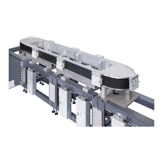
Connecting kit 3 842 559 449 Interface modules 3 842 559 444, 3 842 559 445, 3 842 559 446 Remover tool 3 842 559 439 Calibration set 3 842 559 456 Bosch Rexroth AG, MIT: ActiveMover, 3 842 559 521/2018-07... - Page 17 About this product 17/172 557 186-01 Fig. 1: ActiveMover linear motor system components 3 842 559 521/2018-07, MIT: ActiveMover, Bosch Rexroth AG...
-
Page 18: Base Frame
3 842 559 450 Base frame (short, for curve module only) 3 842 559 451 Hinged foot SW36 (45,5 ... 163,5) SW24 557 186-02 Fig. 2: Base frame for section and curve modules Bosch Rexroth AG, MIT: ActiveMover, 3 842 559 521/2018-07... -
Page 19: Section Module Connecting Kit 3 842 559 452
12 x 40 – A – ST 32 x modules M10 x 40 32 x ISO8375 – 16 x 40 – A – ST 557 186-03 Fig. 3: Connecting kit 3 842 559 452 3 842 559 521/2018-07, MIT: ActiveMover, Bosch Rexroth AG... -
Page 20: Curve Module Connecting Kit 3 842 559 453
3 842 559 450 or 3 842 559 451 with a curve ISO8375 – 16 x 40 – A – ST module 557 186-04 Fig. 4: Connecting kit 3 842 559 453 Bosch Rexroth AG, MIT: ActiveMover, 3 842 559 521/2018-07... -
Page 21: Fixing Plates 3 842 559 454
3 842 559 450 M10 x 40 ISO8375 – 10 x 40 – A – ST 6 x 40 557 186-05 Fig. 5: Connecting kit 3 842 559 454 3 842 559 521/2018-07, MIT: ActiveMover, Bosch Rexroth AG... -
Page 22: Fixing Plate 3 842 559 455
3 842 559 430 on a base M10 x 40 frame 3 842 559 450 or 3 842 559 451 Fixing plate Cable passage 557 186-06 Fig. 6: Fixing plate 3 842 559 455 Bosch Rexroth AG, MIT: ActiveMover, 3 842 559 521/2018-07... -
Page 23: Module Holder 3 842 559 429
Adjusting screw (2x) M6 x 45 T-slot stones (4x) 8 mm Headless setscrew (4x) M6 x 16 M8 x 40 M6 x 45 557 186-07 Module holder 3 842 559 429 Fig. 7: 3 842 559 521/2018-07, MIT: ActiveMover, Bosch Rexroth AG... -
Page 24: Section Module 3 842 559 426
Section module 3 842 559 426 Coil cover M6 x 8 Electronic box Left measuring system (encoder) Right measuring system (encoder) V-rail Run profile Cable guide Centering piece Magnet 557 186-08 Fig. 8: Section module Bosch Rexroth AG, MIT: ActiveMover, 3 842 559 521/2018-07... - Page 25 About this product 25/172 Electronic box PCB (coil) PCB (gateway) PCB (coil) 557 186-09 Fig. 9: Section module with open electronic box 3 842 559 521/2018-07, MIT: ActiveMover, Bosch Rexroth AG...
- Page 26 (0 V) Top left ribbon cable (section module) Bottom left ribbon cable (section module) Cable socket 557 186-10 Fig. 10: Left power supply PCB (shown here with power supply connected) Bosch Rexroth AG, MIT: ActiveMover, 3 842 559 521/2018-07...
- Page 27 (24 V) Network cable connection Control voltage connection (24 V) Network cable connection Top right ribbon cable (section module) Bottom right ribbon cable (section module) 557 186-11 Fig. 11: PCB (gateway) 3 842 559 521/2018-07, MIT: ActiveMover, Bosch Rexroth AG...
- Page 28 (28 V) Bottom right ribbon cable (section module) Top right ribbon cable (section module) Motor cable connection (0 V) Grounding cable connection 557 186-12 Fig. 12: Right power supply PCB Bosch Rexroth AG, MIT: ActiveMover, 3 842 559 521/2018-07...
-
Page 29: Curve Module 3 842 559 430
M: 500 mm guide rail Network cable (Ethernet) Control voltage cable (24 V) Power cable (28 V DC) Grounding cable Power cable (0 V) Cable guard pipe 557 186-13 Fig. 13: Curve module 3 842 559 521/2018-07, MIT: ActiveMover, Bosch Rexroth AG... - Page 30 Fuse (coil) Plug-in connector (coil) Thermo resistor Motor cable connection (0 V) Top left ribbon cable (section module) Bottom left ribbon cable (section module) 557 186-14 Fig. 14: Left power supply PCB Bosch Rexroth AG, MIT: ActiveMover, 3 842 559 521/2018-07...
- Page 31 Network cable connection Control voltage connection (24 V) Network cable connection Top right ribbon cable (section module) Bottom right ribbon cable (section module) 557 186-15 Fig. 15: Printed circuit board (Gateway) 3 842 559 521/2018-07, MIT: ActiveMover, Bosch Rexroth AG...
- Page 32 (28 V) Bottom right ribbon cable (section module) Top right ribbon cable (section module) Motor cable connection (0 V) Grounding cable connection 557 186-16 Fig. 16: Right power supply PCB Bosch Rexroth AG, MIT: ActiveMover, 3 842 559 521/2018-07...
-
Page 33: Workpiece Pallet 3 842 559 433 (2 Magnets)/3 842 559 434 (3 Magnets)
Follow the safety instructions found below in these assembly instructions. Observe the applicable regulations in your country. For Germany, the „ requirements of the BGV B11 and BGR B11 regarding “electromagnetic fields” must be observed. 3 842 559 521/2018-07, MIT: ActiveMover, Bosch Rexroth AG... - Page 34 • Areas where components with permanent magnets are being stored, repaired or installed The persons mentioned above should consult their physician before entering „ these areas. Observe the health and safety regulations applicable in the place of operation. „ Bosch Rexroth AG, MIT: ActiveMover, 3 842 559 521/2018-07...
- Page 35 • Nickel allergies can develop from prolonged contact with objects containing nickel. „ Avoid prolonged skin contact with magnets. Do not handle magnets if you already have a nickel allergy. „ 3 842 559 521/2018-07, MIT: ActiveMover, Bosch Rexroth AG...
- Page 36 Magnets have a max. operating temperature. Most magnets permanently lose some of their pull strength at temperatures over 80 °C. Do not store the magnets where they are exposed to extreme heat. „ Bosch Rexroth AG, MIT: ActiveMover, 3 842 559 521/2018-07...
- Page 37 When workpiece pallets are unmounted, keep their protection plates on them. „ For attachment instructions, see Page 77. Also follow the safety instructions in Section “General safety instructions for „ magnets” on page 33. 3 842 559 521/2018-07, MIT: ActiveMover, Bosch Rexroth AG...
- Page 38 38/172 About this product Base body Measuring system (support and magnetic strip) Positioning element Rubber buffer Detent screw Cover Protective cap Dowel pin 557 186-17 Fig. 17: Workpiece pallet (front view) Bosch Rexroth AG, MIT: ActiveMover, 3 842 559 521/2018-07...
- Page 39 Magnet kit (2 magnets) Guide roller (flat) Positioning element Lubrication system (lubricating felt + support + fastening element) Magnet kit (3 magnets) Protection plate 557 186-18 Fig. 18: Workpiece pallet (rear view) 3 842 559 521/2018-07, MIT: ActiveMover, Bosch Rexroth AG...
-
Page 40: Ir Id System
The IR data carrier has a preassigned number and cannot be reprogrammed. This number is engraved on the edge of the IR data carrier. 557 186-19 Fig. 19: IR ID system components Bosch Rexroth AG, MIT: ActiveMover, 3 842 559 521/2018-07... -
Page 41: Power Supply 3 842 559 435
Alternative plug connector (230 V AC) PLC monitor connection output (24 V DC) Filter Fixing plate Mounting bracket Connecting cable (0 V, 28 V DC) 557 186-20 Fig. 20: Power supply 3 842 559 521/2018-07, MIT: ActiveMover, Bosch Rexroth AG... -
Page 42: Control Cabinet 3 842 559 459 And 3 842 559 462
Main switch PLC controller connection AMpro connection Filter Power port Connection for connecting kit 3 842 559 449 PLC controller connection (optional) Power supply connection 557 186-21 Fig. 21: Control cabinet Bosch Rexroth AG, MIT: ActiveMover, 3 842 559 521/2018-07... - Page 43 Power cable (28 V DC, blue) Grounding cable Power cable (0 V DC, blue/white) Cable guard pipe Control voltage cable (24 V) 557 186-22 Fig. 22: Connecting kit 3 842 559 438 3 842 559 521/2018-07, MIT: ActiveMover, Bosch Rexroth AG...
-
Page 44: Connecting Kit 3 842 559 449
Network cable (7,600 mm) Control voltage cable (24 V DC/0 V) Network cable (1,000 mm) Ferrite Cable guard pipe (6,500 mm) 557 186-23 Fig. 23: Connecting kit 3 842 559 449 Bosch Rexroth AG, MIT: ActiveMover, 3 842 559 521/2018-07... -
Page 45: Interface Modules 3 842 559 444, 3 842 559 445, 3 842 559 446
Interface modules 3 842 559 444, 3 842 559 445, 3 842 559 446 Interface modules with various protocols for connecting to a higher-level controller 557 186-24 Fig. 24: Interface modules 3 842 559 521/2018-07, MIT: ActiveMover, Bosch Rexroth AG... -
Page 46: Remover Tool 3 842 559 439
46/172 About this product 5.2.16 Remover tool 3 842 559 439 Tool for removing/mounting workpiece pallets Remover tool Locking hook 557 186-25 Fig. 25: Remover tool 3 842 559 439 Bosch Rexroth AG, MIT: ActiveMover, 3 842 559 521/2018-07... -
Page 47: Calibration Set 3 842 559 456
The calibration set is required to adjust/calibrate the measuring system on the WT. Position indicator Reference system Aligning block Knurled thumbscrew Fixing element Knurled thumbscrew 557 186-26 Fig. 26: Calibration set 3 842 559 521/2018-07, MIT: ActiveMover, Bosch Rexroth AG... -
Page 48: Product Identification
Make sure the lifting straps are correctly fastened before lifting the product. „ „ Secure the product against tipping over during lifting. Make sure no one but the operator is in the hazard zone during lifting and lowering. „ Bosch Rexroth AG, MIT: ActiveMover, 3 842 559 521/2018-07... -
Page 49: Storing The Product
• Precision straight edge • 0.1, 0.2, 0.25, 0.5 mm shims 7.3.2 Electrical • Various screwdrivers with insulated handles • Wire cutters with insulated handles • Wire stripper with insulated handles • Multimeter 3 842 559 521/2018-07, MIT: ActiveMover, Bosch Rexroth AG... -
Page 50: Symbols Used
Identification of components in illustrations. The letters identify the components mentioned in the accompanying text. Detail view from a different direction, e.g. the back or the bottom of the product. Bosch Rexroth AG, MIT: ActiveMover, 3 842 559 521/2018-07... -
Page 51: Assembling The Product
Mount additional system sections with section/curve modules on the left and „ right in a symmetrical manner. Make sure all other mounted system sections are plumb, level and square with „ the reference system section. 3 842 559 521/2018-07, MIT: ActiveMover, Bosch Rexroth AG... - Page 52 Assemble the profile connectors on the back side of the joint between the „ section/curve modules. Adjust the transition of the V-rail with the profile connector. „ Check the transition between the section/curve modules with a workpiece pallet. „ Bosch Rexroth AG, MIT: ActiveMover, 3 842 559 521/2018-07...
-
Page 53: Setting Up And Aligning A Base Frame
= 0,02 mm/m SW36 (45,5 ... 163,5) SW24 557 186-30 Fig. 30: Setting up and aligning a base frame 3 842 559 450 3 842 559 521/2018-07, MIT: ActiveMover, Bosch Rexroth AG... - Page 54 Use a precision level to (45,5 ... 163,5) make sure both base SW24 frames are level, plumb and square. 557 186-31 Fig. 31: Setting up and aligning a base frame 3 842 559 451 Bosch Rexroth AG, MIT: ActiveMover, 3 842 559 521/2018-07...
-
Page 55: Mounting Section Module On A Base Frame
ISO8375 – 16 x 40 – A – ST ISO8375 – 12 x 40 – A – ST 557 186-32 Fig. 32: Mounting fixing plates (1) 3 842 559 521/2018-07, MIT: ActiveMover, Bosch Rexroth AG... - Page 56 Assembly Screw down the fixing plates. Hammer 4 straight M10 x 40 pins halfway into the =43 Nm fixing plates. M6 x 40 557 186-33 Fig. 33: Mounting fixing plates (2) Bosch Rexroth AG, MIT: ActiveMover, 3 842 559 521/2018-07...
- Page 57 Screw the headless setscrew through the T-slot stones and into the run profile. =7 Nm 557 186-34 Fig. 34: Mounting module holder on a section module (1) 3 842 559 521/2018-07, MIT: ActiveMover, Bosch Rexroth AG...
- Page 58 Install the module holders and align them. =7 Nm =7 Nm 600,00 199,75 199,75 4 , 5 4 , 5 557 186-35 Fig. 35: Mounting module holder on a section module (2) Bosch Rexroth AG, MIT: ActiveMover, 3 842 559 521/2018-07...
- Page 59 Push the section module against the straight pin. Tighten the fastening screws. 6 x 40 =18 Nm 557 186-36 Fig. 36: Mounting section module on a base frame (1) 3 842 559 521/2018-07, MIT: ActiveMover, Bosch Rexroth AG...
- Page 60 =7 Nm „ Mount the second section module on the base frame accordingly. =7 Nm 557 186-37 Fig. 37: Mounting section module on a base frame (2) Bosch Rexroth AG, MIT: ActiveMover, 3 842 559 521/2018-07...
- Page 61 Fig. 35. If necessary, repeat/check the entire assembly. = 0,02 mm/m 557 186-38 Fig. 38: Checking section module alignment 3 842 559 521/2018-07, MIT: ActiveMover, Bosch Rexroth AG...
-
Page 62: Mounting Curve Module On A Base Frame
Insert an adjusting screw in each curve module holder. M8 x 75 fastening screw M6 spring washer Adjusting screw Lock nut 557 186-39 Fig. 39: Mounting curve module on a base frame (1) Bosch Rexroth AG, MIT: ActiveMover, 3 842 559 521/2018-07... - Page 63 Tighten the fastening screws in the fixing SW?? plate. = ??Nm Install the module holder covers. Install the curve module cover. 557 186-40 Fig. 40: Mounting curve module on a base frame (2) 3 842 559 521/2018-07, MIT: ActiveMover, Bosch Rexroth AG...
-
Page 64: Adding And Connecting System Sections
Loosen the top lock SW24 nut (D) and screw the leveling foot (F) in or out accordingly. Tighten the top lock nut. (4x) 557 186-41 Fig. 41: Checking system section alignment Bosch Rexroth AG, MIT: ActiveMover, 3 842 559 521/2018-07... - Page 65 16x40 of the reference system section (A) and fix them 12x40 3 842 559 453 with straight pins. Tighten both top connection plates. 557 186-42 Fig. 42: Mounting upper connecting plate 3 842 559 521/2018-07, MIT: ActiveMover, Bosch Rexroth AG...
- Page 66 Tighten the top connection plate somewhat. Mount the side connection plates loosely (on both sides). (4x) 557 186-43 Fig. 43: Connecting system sections (2 section modules shown here) (1) Bosch Rexroth AG, MIT: ActiveMover, 3 842 559 521/2018-07...
- Page 67 X = 0,5 mm (on both sides). Add all other system „ sections in the same fashion. =80 Nm =80 Nm 557 186-44 Fig. 44: Connecting system sections (2) 3 842 559 521/2018-07, MIT: ActiveMover, Bosch Rexroth AG...
-
Page 68: Aligning Section Modules (Rough Adjustment)
X = 0,5 mm 0.5 mm from each other. Tighten the fastening screws. =18 Nm 557 186-45 Fig. 45: Adjusting lateral offset of section modules (rough adjustment) Bosch Rexroth AG, MIT: ActiveMover, 3 842 559 521/2018-07... - Page 69 0.5 mm from each other. Tighten the fastening screws. SW13 =21 Nm X = 0,5 mm =7 Nm 557 186-46 Fig. 46: Adjusting height offset of section modules (rough adjustment) 3 842 559 521/2018-07, MIT: ActiveMover, Bosch Rexroth AG...
-
Page 70: Installing Profile Connectors
T-slots of the section modules and tighten the screws. Tighten the lock screws in the T-slot stones. =16 Nm =16 Nm 557 186-47 Fig. 47: Installing profile connector between 2 section modules Bosch Rexroth AG, MIT: ActiveMover, 3 842 559 521/2018-07... - Page 71 (M6 x 45). Tighten the lock screws in the T-slot stones. M6 x 45 (2x) =16 Nm =16 Nm 557 186-48 Fig. 48: Installing profile connector between section module and curve module 3 842 559 521/2018-07, MIT: ActiveMover, Bosch Rexroth AG...
-
Page 72: Aligning The V-Rail (Fine Adjustment)
Adjust the height offset (see Fig. 50 on page 73). Adjust the lateral offset (see Fig. 51 on page 73). 557 186-49 Fig. 49: Checking height and lateral offset of the V-rail Bosch Rexroth AG, MIT: ActiveMover, 3 842 559 521/2018-07... - Page 73 Rotational Adjustment direction Right Left Tighten the fastening screws for the connecting kit. 557 186-51 Fig. 51: Adjusting lateral offset to ≤ ±0.05 mm (fine adjustment) 3 842 559 521/2018-07, MIT: ActiveMover, Bosch Rexroth AG...
- Page 74 Insert a spacer of the required thickness in the same location. Install the V-rail and „ measuring system (encoder) in reverse order. 557 186-52 Fig. 52: Adjusting lateral offset to > ±0.05 mm Bosch Rexroth AG, MIT: ActiveMover, 3 842 559 521/2018-07...
-
Page 75: Mounting And Aligning Guide Rails
(D) in the adjuster until = Nm you can no longer feel an offset between the guide rails. Tighten the screws in the adjuster (C). 557 186-53 Fig. 53: Mounting and aligning guide rails 3 842 559 521/2018-07, MIT: ActiveMover, Bosch Rexroth AG... -
Page 76: Mounting/Removing Workpiece Pallets
Be prepared for the high pull strength. „ Set the protection plate on the magnet kit with the plastic cover on. „ „ Do not put any body parts between the protection plate and the magnet kit. Bosch Rexroth AG, MIT: ActiveMover, 3 842 559 521/2018-07... - Page 77 Attach the remover tool (shorter arm on the left). Secure the remover tool with the locking hook (B) and the detent screw (C). 557 186-54 Fig. 54: Mounting workpiece pallet (1) 3 842 559 521/2018-07, MIT: ActiveMover, Bosch Rexroth AG...
- Page 78 Detach the remover tool. Check the spacing of the measuring system (encoder and magnetic strip), see Section 10.5.1. „ Disassemble in reverse order. 557 186-55 Fig. 55: Mounting workpiece pallet (2) Bosch Rexroth AG, MIT: ActiveMover, 3 842 559 521/2018-07...
-
Page 79: Mounting, Adjusting And Connecting Id System Ir Reading Head
(E) and move the = Nm support of the IR reading head bracket. =5 Nm 1,0 mm 557 186-56 Fig. 56: Mounting and adjusting IR reading head 3 842 559 521/2018-07, MIT: ActiveMover, Bosch Rexroth AG... - Page 80 Connect the connecting cable for the IR reading head to the PCB (gateway). 557 186-57 Fig. 57: Connecting ID system IR reading head Bosch Rexroth AG, MIT: ActiveMover, 3 842 559 521/2018-07...
-
Page 81: Mounting Power Supply
Drill 4 mounting holes according to the drawing dimensions. Install the mounting plate. Install the power supply. Ø5 0 , 2 = Nm = Nm 557 186-58 Fig. 58: Mounting power supply 3 842 559 521/2018-07, MIT: ActiveMover, Bosch Rexroth AG... -
Page 82: Connecting Product To Power
Secure the system against unintentional restarting. „ CAUTION Uninterruptible power supply! Voltage may be present even with the main switch off! Coming into contact with electrical components can result in injury and burns from electric shock. Bosch Rexroth AG, MIT: ActiveMover, 3 842 559 521/2018-07... - Page 83 • Observe the established line voltage. • Observe the electrical ratings on the nameplate, see Fig. 27 on page 48. • Observe the circuit diagram included in the scope of delivery. 3 842 559 521/2018-07, MIT: ActiveMover, Bosch Rexroth AG...
-
Page 84: Installing Emc Cable Glands And Cable Guard Pipes
Push the cable guard pipe (C) into the cable glands between the section/curve modules. Tighten the cable glands. 557 186-59 Fig. 59: Installing EMC cable glands and cable guard pipes Bosch Rexroth AG, MIT: ActiveMover, 3 842 559 521/2018-07... -
Page 85: Inserting Connecting Cables
Network cable (Ethernet) Power cable (28 V DC) Grounding cable Power cable (0 V) Control voltage cable (24 V) 557 186-60 Fig. 60: Inserting connecting cables (shown here in a section module) 3 842 559 521/2018-07, MIT: ActiveMover, Bosch Rexroth AG... -
Page 86: Inserting Power Supply Line In Section/Curve Module
Remove the caps. Install the cable glands. Insert the power supply cable through the cable gland. Tighten the cable glands. 557 186-61 Fig. 61: Inserting power supply line in section/curve module Bosch Rexroth AG, MIT: ActiveMover, 3 842 559 521/2018-07... -
Page 87: Connecting Ground And Power Cables (28 V) (From Left Section/Curve Module)
(28 V DC, blue) to Terminal G. Connect the power cable (0 V, blue/white) to Terminal H. 557 186-62 Fig. 62: Connecting ground and power cables (from left section/curve module without power supply connected) 3 842 559 521/2018-07, MIT: ActiveMover, Bosch Rexroth AG... -
Page 88: Connecting Ground And Power Cables (28V) (From Right Section/Curve Module)
Connect the power cable (28 V DC, blue) to Terminal D. Connect the power cable (0 V, blue/white) to 557 186-63 Fig. 63: Connecting ground and power cables (right section/curve module) Terminal I. Bosch Rexroth AG, MIT: ActiveMover, 3 842 559 521/2018-07... -
Page 89: Connecting Network And Control Voltage Cables (24 V) (From Left Section/Curve Module)
Terminal H on the PCB (gateway). Connect the control voltage cable (24 V) to Terminal G. 557 186-64 Fig. 64: Connecting network and control voltage cables (from left section/curve module) 3 842 559 521/2018-07, MIT: ActiveMover, Bosch Rexroth AG... -
Page 90: Connecting Network And Control Voltage Cables (24 V) (From Right Section/Curve Module)
Fig. 65: Connecting network cable (from right section/curve module) 7.6.8 Connecting the network connections and power supplies in the control cabinet Please refer to the corresponding information from the circuit diagram. „ Bosch Rexroth AG, MIT: ActiveMover, 3 842 559 521/2018-07... -
Page 91: Id System Ir Reading Head (Optional)
Connect the connecting cable for the IR reading head to the PCB (gateway). 557 186-66 Fig. 66: Connecting ID system IR reading head (optional) 3 842 559 521/2018-07, MIT: ActiveMover, Bosch Rexroth AG... -
Page 92: Network
RJ45 Left network cable to controller Right section end Left section end Left section start M: Network connection Feed module Left network connection cable Control cabinet 557 186-67 Fig. 67: Connecting PCBs (gateway) Bosch Rexroth AG, MIT: ActiveMover, 3 842 559 521/2018-07... - Page 93 Connect the network „ cable according to the circuit diagram. RJ45 Right network cable RJ45 Left network cable Right network Network connection Left network 557 186-68 Fig. 68: Left and right network connection 3 842 559 521/2018-07, MIT: ActiveMover, Bosch Rexroth AG...
-
Page 94: Connecting Power Supply In The Section Module
Connect the power cable (28 V DC, blue) to Terminal B. Connect the power cable (0 V, blue/white) to Terminal H. 557 186-69 Fig. 69: Connecting power supply in the section module Bosch Rexroth AG, MIT: ActiveMover, 3 842 559 521/2018-07... -
Page 95: Connecting Power Supply In The Curve Module
Connect the power cable (28 V DC, blue) to Terminal A. Connect the power cable (0 V, blue/white) to Terminal B. 557 186-70 Fig. 70: Connecting power supply in the curve module 3 842 559 521/2018-07, MIT: ActiveMover, Bosch Rexroth AG... -
Page 96: Connecting Power Supply In The Control Cabinet
Insert the plug connector (230 V AC) for the power cable into the power supply. 557 186-71 Fig. 71: Connecting power supply in the control cabinet Bosch Rexroth AG, MIT: ActiveMover, 3 842 559 521/2018-07... -
Page 97: Ethernet Powerlink
Connect the ActiveMover „ controller to the bus controller according to the circuit diagram. Ethernet port Ethernet port 557 186-72 Fig. 72: Ethernet POWERLINK connection 3 842 559 521/2018-07, MIT: ActiveMover, Bosch Rexroth AG... -
Page 98: Ethernet Port (Windows Pc)
• The connecting cable is not included in the scope of delivery. Connect the Ethernet „ port according to the circuit diagram. Ethernet port 557 186-73 Fig. 73: Ethernet port connection Bosch Rexroth AG, MIT: ActiveMover, 3 842 559 521/2018-07... -
Page 99: Plc
(B). Connect the PLC according to the circuit diagram. Configure the rotary switch as shown in the illustration. 557 186-74 Fig. 74: PLC connection PLC connection Cable socket 3 842 559 521/2018-07, MIT: ActiveMover, Bosch Rexroth AG... -
Page 100: Emergency Stop Safety Circuit
• The necessary performance level under DIN EN ISO 13849 should be PL = d. • It should not be possible to start the ActiveMover with the safety door open. Connect the emergency stop safety circuits according to the circuit diagram. „ Bosch Rexroth AG, MIT: ActiveMover, 3 842 559 521/2018-07... -
Page 101: Line Voltage
(A). Connect the line voltage according to the circuit diagram. Screw down the cable gland. 557 186-75 Fig. 75: Cable gland for line voltage cable 3 842 559 521/2018-07, MIT: ActiveMover, Bosch Rexroth AG... -
Page 102: Start-Up
EMERGENCY STOP controls. • Make sure all electrical connections are either used or capped. Make sure all thread connectors and plug-in connectors are properly seated. All relevant protective covers must be installed. Bosch Rexroth AG, MIT: ActiveMover, 3 842 559 521/2018-07... - Page 103 • Only start up the product if all safety equipment has been installed in the system and is functional. • Only start up a product that has been fully installed. 3 842 559 521/2018-07, MIT: ActiveMover, Bosch Rexroth AG...
-
Page 104: Residual Risks
1 Life stages of the machine according to EN 12100 Section 5.4 a /b (No. 1–27), Section 5.4 a (see Page 105). 6, 7 1, 2, 3, 4 557 186-198 557 186-199 Bosch Rexroth AG, MIT: ActiveMover, 3 842 559 521/2018-07... -
Page 105: Life Stages Of The Machine
The AMpro configuration software is required for start-up, configuration, parameterization, calibration and troubleshooting. For the description of the software, see the separate AMpro manual. You can download the manual online at: www.boschrexroth.com/mediadirectory 3 842 559 521/2018-07, MIT: ActiveMover, Bosch Rexroth AG... -
Page 106: Operation
(e.g. welding beads, pumice powder, cullet, chips, waste parts, etc.) – can greatly increase wear. Maintenance intervals should be significantly reduced under these circumstances. Bosch Rexroth AG, MIT: ActiveMover, 3 842 559 521/2018-07... - Page 107 – If carried onto systems with rollers, media with a lubricating effect can lead to a reduction in the drive power transmitted via friction. In such instances, special care should be taken when planning the system and the maintenance intervals should be shortened accordingly. 3 842 559 521/2018-07, MIT: ActiveMover, Bosch Rexroth AG...
-
Page 108: Maintenance And Servicing
Risk of burns from touching hot surfaces over 65 °C. Install appropriate guards. „ „ Allow the system to cool down for at least 30 min before performing maintenance and/or servicing. Bosch Rexroth AG, MIT: ActiveMover, 3 842 559 521/2018-07... - Page 109 Risk of crushing when mounting/removing workpiece pallets The other workpiece pallets near the remover tool pose a risk of hands and fingers being crushed. Remove all workpiece pallets near the remover tool. „ 3 842 559 521/2018-07, MIT: ActiveMover, Bosch Rexroth AG...
-
Page 110: Cleaning And Care
Clean deposits and fouling from the V-rail and guide rails at least once per week with isopropyl alcohol (IPA) and a clean, soft cloth. After cleaning with isopropyl alcohol, the V-rail and guide rails must be relubricated to avoid damaging the WTs. Bosch Rexroth AG, MIT: ActiveMover, 3 842 559 521/2018-07... -
Page 111: Section/Curve Module Base Frame
For disassembling the measuring system, see Section 10.4.5. For inspecting the measuring system, see Section 10.2.6. 10.1.5 Control cabinet fan Clean deposits and fouling from the fan with a clean, soft cloth as needed. 3 842 559 521/2018-07, MIT: ActiveMover, Bosch Rexroth AG... -
Page 112: Inspection
Replace the guide rails, if necessary (see Section Fig. 53). Check the vertical and Replace the guide rollers, if horizontal play of the guide necessary (see Section 10.4.9). rollers. Slight vertical play is normal. Bosch Rexroth AG, MIT: ActiveMover, 3 842 559 521/2018-07... -
Page 113: Control Cabinet Fan
Inspect the control cabinet power supply for dust and fouling at least once per month. For replacing the air filter, see Section 10.4.25. 10.2.5 All screws Inspect all ActiveMover components for loose fastenings and screws at least once per month. 3 842 559 521/2018-07, MIT: ActiveMover, Bosch Rexroth AG... -
Page 114: Inspecting The Measuring System (Magnetic Strip)
All poles in the measuring system (magnetic strip) should be parallel to one another and easily visible. 557 186-76 Fig. 76: Inspecting the measuring system Should individual poles not be visible or appear damaged, replace the measuring system (magnetic strip). Bosch Rexroth AG, MIT: ActiveMover, 3 842 559 521/2018-07... -
Page 115: Maintenance
Afterward, lubricate as needed per Table 7 on Page 112. Please note: The workpiece pallet does No-Tox®HD Food Grade not have to be removed for Oil 46 5 ... 10 lubrication. 557 186-77 Fig. 77: Lubricating the workpiece pallet 3 842 559 521/2018-07, MIT: ActiveMover, Bosch Rexroth AG... -
Page 116: Servicing
When workpiece pallets are unmounted, keep their protection plates on them. „ For attachment instructions, see Page 77. Also follow the safety instructions in Section “General safety instructions for „ magnets” on page 33. Bosch Rexroth AG, MIT: ActiveMover, 3 842 559 521/2018-07... - Page 117 Do not put any body parts between the protection plate and the magnet kit. „ NOTICE Risk of destruction of electronic components/PCBs by ESD „ Always wear an anti-static wristband to prevent electrostatic charging when working on electronic components/PCBs. 3 842 559 521/2018-07, MIT: ActiveMover, Bosch Rexroth AG...
-
Page 118: Replacing Rubber Buffers
(see Section 7.5.10). Set the protection plate on the magnet kit with the plastic cover on. Remove the rubber buffers. Install the new rubber buffers. 557 186-78 Fig. 78: Replacing rubber buffers Bosch Rexroth AG, MIT: ActiveMover, 3 842 559 521/2018-07... -
Page 119: Replacing Discharger Brushes
Align the discharger brushes with the outer 557 186-79 Fig. 79: Replacing discharger brushes holes in the tip guard. Install the fastening screws for the discharger brushes and tighten them. 3 842 559 521/2018-07, MIT: ActiveMover, Bosch Rexroth AG... -
Page 120: Replacing The Measuring System
Remove the measuring system. Install the new measuring system in reverse order. Check the spacing of the measuring system (encoder and magnetic strip), see Section 10.5.1. Recalibrate the WT (see Section 10.5.4 ff). Bosch Rexroth AG, MIT: ActiveMover, 3 842 559 521/2018-07... -
Page 121: Replacing The Felt (Wt Lubricating Device)
Lubricate the WT 557 186-81 Fig. 81: Replacing the felt (WT lubricating device) (see Section 10.3.1). Please note: The V-groove in the felt should be arranged horizontally in the V-rollers. 3 842 559 521/2018-07, MIT: ActiveMover, Bosch Rexroth AG... -
Page 122: Replacing The Pressure Spring
(see Section 10.4.6). Remove the pressure springs. Install the new pressure = Nm spring and lubricating felt holder in reverse order. 557 186-82 Fig. 82: Replacing the pressure spring Bosch Rexroth AG, MIT: ActiveMover, 3 842 559 521/2018-07... -
Page 123: Replacing The Magnet Kit
• The kit with 3 magnets is fastened with 4 screws. Install the new magnet kit and the front plate in reverse order. 557 186-83 Fig. 83: Replacing the magnet kit 3 842 559 521/2018-07, MIT: ActiveMover, Bosch Rexroth AG... -
Page 124: Replacing Guide Rollers (Flat)
Remove the guide rollers and washers. Install the new guide rollers and washers (2 per guide roller) in reverse order. 557 186-84 Fig. 84: Replacing guide rollers (flat) Bosch Rexroth AG, MIT: ActiveMover, 3 842 559 521/2018-07... -
Page 125: Replacing V-Rollers
Remove the hex socket screws. Remove the shims. Remove the bearing pins. Remove the guide rollers. Install the new guide rollers in reverse order. 557 186-85 Fig. 85: Replacing V-rollers 3 842 559 521/2018-07, MIT: ActiveMover, Bosch Rexroth AG... -
Page 126: Replacing The V-Rail (Section Module)
Replacing the V-rail (section module) Please note: • The V-grooves on both sides of the V-rail prevent it from rising. • The gaps at both ends of the V-rail should be approx. 0.5 mm. Bosch Rexroth AG, MIT: ActiveMover, 3 842 559 521/2018-07... -
Page 127: Replacing The V-Rail (Curve Module)
Install the V-rail in reverse order. If necessary, align the V-rail (see Section 7.5.8). Calibrate the measuring system sensor units (see Section 10.5). 557 186-87 Fig. 87: Replacing the V-rail (curve module) 3 842 559 521/2018-07, MIT: ActiveMover, Bosch Rexroth AG... -
Page 128: Replacing Guide Rails (Section Module)
To install the new guide rail, see Fig. 53 on Page 75. 557 186-88 Fig. 88: Replacing guide rails (section module) Bosch Rexroth AG, MIT: ActiveMover, 3 842 559 521/2018-07... -
Page 129: Replacing The Coil Cover (Section/Curve Module)
Put the cover on the top corner of the coil and press the cover on carefully from top to bottom. Press out any air bubbles from the inside out. 3 842 559 521/2018-07, MIT: ActiveMover, Bosch Rexroth AG... -
Page 130: Replacing The Power Supply
Remove the power supply from the mounting plate. Mount and connect the „ new power supply in reverse order. 557 186-90 Fig. 90: Replacing the power supply Bosch Rexroth AG, MIT: ActiveMover, 3 842 559 521/2018-07... -
Page 131: Replacing The Power Supply Pcb (Section Module)
Disconnect the 2 ribbon cables from the PCB. Disconnect the 5 coil plugs. 557 186-91 Fig. 91: Replacing the power supply PCB (section module) 3 842 559 521/2018-07, MIT: ActiveMover, Bosch Rexroth AG... - Page 132 Check that all 10 fuses (15 A) are present on the new PCB. Install the new PCB in „ reverse order. 557 186-92 Fig. 92: Replacing the power supply PCB (section module) Bosch Rexroth AG, MIT: ActiveMover, 3 842 559 521/2018-07...
-
Page 133: Replacing The Power Supply Pcb (Curve Module)
Check that all 10 fuses (15 A) are present on the new PCB. Install the new PCB in „ reverse order. Plastic 557 186-93 Fig. 93: Replacing the power supply PCB (curve module) 3 842 559 521/2018-07, MIT: ActiveMover, Bosch Rexroth AG... -
Page 134: Replacing The Pcb (Gateway) (Section Module)
Disconnect the 2 ribbon cables from the 24 V power supply. Disconnect the network cable (1 or 2). Disconnect the 4 ribbon cables. 557 186-94 Fig. 94: Replacing the PCB (gateway) (section module) Bosch Rexroth AG, MIT: ActiveMover, 3 842 559 521/2018-07... - Page 135 3 plastic discs on all 4 fastening screws in the new PCB (gateway). Install the new PCB „ (gateway) in reverse order. 557 186-95 Fig. 95: Replacing the PCB (gateway) (section module) 3 842 559 521/2018-07, MIT: ActiveMover, Bosch Rexroth AG...
-
Page 136: Replacing The Pcb (Gateway) (Curve Module)
Disconnect the 2 ribbon cables from the 24 V power supply. Disconnect the 4 ribbon cables. Disconnect the 2 encoder cables. 557 186-96 Fig. 96: Replacing the PCB (gateway) (curve module) Bosch Rexroth AG, MIT: ActiveMover, 3 842 559 521/2018-07... - Page 137 3 plastic discs on all 4 fastening screws in the new PCB (gateway). Install the new PCB „ (gateway) in reverse order. 557 186-97 Fig. 97: Replacing the PCB (gateway) (curve module) 3 842 559 521/2018-07, MIT: ActiveMover, Bosch Rexroth AG...
-
Page 138: Replacing Drive Thermistors
Install the new thermistor in reverse order. Please note: The thermistor needs to be pushed all the way into the thermistor mounting. 557 186-98 Fig. 98: Replacing drive thermistor Bosch Rexroth AG, MIT: ActiveMover, 3 842 559 521/2018-07... -
Page 139: Replacing The Main Fuse (Section/Curve Module)
Install the new main fuse (50 A) in reverse order. Please note: Install the main fuse with a screws, lock washers and regular washers. 557 186-99 Fig. 99: Replacing the main fuse (section/curve module) 3 842 559 521/2018-07, MIT: ActiveMover, Bosch Rexroth AG... -
Page 140: Replacing The Coil Fuse (Section/Curve Module)
Pull the coil fuse out of the fuse holder. Install the new (15 A) coil fuse in reverse order. 557 186-100 Fig. 100: Replacing the coil fuse (section/curve module) Bosch Rexroth AG, MIT: ActiveMover, 3 842 559 521/2018-07... -
Page 141: Replacing The Measuring System (Encoder) (Section Module)
Disconnect the connecting cable. Install the new sensor unit in reverse order. Calibrate the new sensor unit (see Section 10.5). 557 186-101 Fig. 101: Replacing the measuring system (encoder) (section module) 3 842 559 521/2018-07, MIT: ActiveMover, Bosch Rexroth AG... -
Page 142: Replacing The Measuring System (Encoder) (Curve Module)
Disconnect the connecting cable. Install the new sensor units in reverse order. Calibrate the new sensor units (see Section 10.5). 557 186-102 Fig. 102: Replacing the measuring system (encoder) (curve module) Bosch Rexroth AG, MIT: ActiveMover, 3 842 559 521/2018-07... -
Page 143: Replacing The Activemover Power Supply Air Filter
3 842 555 969 Remove the retaining clip from the air filter. Replace the air filter. Install the retaining clip. 557 186-103 Fig. 103: Replacing the ActiveMover power supply air filter 3 842 559 521/2018-07, MIT: ActiveMover, Bosch Rexroth AG... -
Page 144: Adjustment And Calibration
Table 7 on page 112 • Proper installation of the measuring system (see Section 10.4.5) Check the spacing (X) between measuring system and sensor unit. 557 186-104 Fig. 104: Checking measuring system distance Bosch Rexroth AG, MIT: ActiveMover, 3 842 559 521/2018-07... - Page 145 Remove the shim. Install a suitable shim to maintain the spacing X = 0.5 mm (± 0.3 mm). Assemble in the reverse order. 557 186-105 Fig. 105: Setting measuring system distance 3 842 559 521/2018-07, MIT: ActiveMover, Bosch Rexroth AG...
-
Page 146: Primary And Secondary Measuring System
• The secondary measuring system comes calibrated and should not need to be recalibrated under normal circumstances. Primary measuring system Secondary measuring system 557 186-106 Fig. 106: Primary and secondary measuring system Bosch Rexroth AG, MIT: ActiveMover, 3 842 559 521/2018-07... -
Page 147: Encoder Numbering And Order
0 and ends at the right side of the right sensor with 15. 557 186-107 Fig. 107: Encoder numbering and order 3 842 559 521/2018-07, MIT: ActiveMover, Bosch Rexroth AG... -
Page 148: Installing And Aligning The Calibration Set (Optional)
V-rail as possible, insert suitable shims between the fixing element and the sensor unit. 557 186-108 Fig. 108: Installing measuring system adjusting tool (1) Bosch Rexroth AG, MIT: ActiveMover, 3 842 559 521/2018-07... - Page 149 V-rail = Nm with a dial indicator mounted to the WT. = Nm 557 186-109 Fig. 109: Installing calibration set (2) 3 842 559 521/2018-07, MIT: ActiveMover, Bosch Rexroth AG...
- Page 150 Fixture „ „ Setup. Click on the encoder on which the fixing element is centered (odd number). Click on Accept. 557 186-110 Fig. 110: Aligning fixing element to an encoder (1) Bosch Rexroth AG, MIT: ActiveMover, 3 842 559 521/2018-07...
- Page 151 The indicated value of 158 and the arrow mean the calibration set needs to be moved 158 µm to the links. 557 186-111 Fig. 111: Aligning fixing element to an encoder (2) 3 842 559 521/2018-07, MIT: ActiveMover, Bosch Rexroth AG...
- Page 152 (ideal value is 0). Tighten the fixing = Nm element screws. SW13 Tighten the adjusting screw lock nuts. SW13 = Nm 557 186-112 Fig. 112: Aligning fixing element to an encoder (3) Bosch Rexroth AG, MIT: ActiveMover, 3 842 559 521/2018-07...
- Page 153 Push the adjusting blocks against the fixing element. Tighten the fastening screws. Remove the position indicator. = Nm = Nm 557 186-113 Fig. 113: Aligning fixing element to an encoder (4) 3 842 559 521/2018-07, MIT: ActiveMover, Bosch Rexroth AG...
-
Page 154: Checking Calibration Set Position
Depending on the tightening torque of the knurled thumbscrew, the position can vary by ±5 µm. Always apply the same tightening torque. 557 186-114 Fig. 114: Checking calibration set position (1) Bosch Rexroth AG, MIT: ActiveMover, 3 842 559 521/2018-07... - Page 155 „ Strip Setup. Click on the encoder on which the fixing element is centered (odd number). The display should read ±4 µm. 557 186-115 Fig. 115: Checking calibration set position (2) 3 842 559 521/2018-07, MIT: ActiveMover, Bosch Rexroth AG...
-
Page 156: Referencing Encoder Position
Move the WT 15 cm to the right. 557 186-116 Fig. 116: Referencing encoder position Click on Save Parameters. The Save Configuration window opens. Encoder Configuration is preselected. Click on OK. Bosch Rexroth AG, MIT: ActiveMover, 3 842 559 521/2018-07... -
Page 157: Adjusting The Primary Measuring System
WT under the reference system. Do not let the WT collide with the reference system. Flip the knurled thumbscrew down. Gently press the WT to the left and tighten the knurled thumbscrew slightly. 3 842 559 521/2018-07, MIT: ActiveMover, Bosch Rexroth AG... - Page 158 • Do not overtighten the adjusting screws. This could move the calibration set. Tighten the measuring system screws. Check the display again. 557 186-118 Fig. 118: Checking calibration set position (2) Bosch Rexroth AG, MIT: ActiveMover, 3 842 559 521/2018-07...
-
Page 159: Adjusting The Secondary Measuring System
Flip the knurled thumbscrew down. Gently press the WT to the left and tighten the knurled thumbscrew slightly. 557 186-119 Fig. 119: Adjusting the secondary measuring system (1) 3 842 559 521/2018-07, MIT: ActiveMover, Bosch Rexroth AG... - Page 160 Repeat steps 6 to 8. Monitor the fine adjustment value and use the helper screws to move the measuring system until the display turns green. 557 186-120 Fig. 120: Adjusting the secondary measuring system (2) Bosch Rexroth AG, MIT: ActiveMover, 3 842 559 521/2018-07...
- Page 161 Maintenance and servicing 161/172 Tighten the measuring system screws. Check the display again. Click on Finish. Remove the helper screws. 557 186-121 Fig. 121: Adjusting the secondary measuring system (3) 3 842 559 521/2018-07, MIT: ActiveMover, Bosch Rexroth AG...
-
Page 162: Installing/Removing The Wt Mount (Optional)
WT mount to the support. Tighten the knurled thumbscrew slightly. The knurled thumbscrew has a friction clutch. Disassemble in reverse „ order. 557 186-122 Fig. 122: Installing/removing the WT mount Bosch Rexroth AG, MIT: ActiveMover, 3 842 559 521/2018-07... -
Page 163: Troubleshooting
Let ActiveMover controller boot up and check whether controller starts in RUN mode. If fault persists, repeat max. 4–5x, then contact Bosch Rexroth Service. 11.2 Power supply and workpiece pallets Consult the Help function in the AMpro configuration software for suggestions on correcting faults in the power supply and workpiece pallets. -
Page 164: Diagnostic Leds
(in the section/curve module electronic box) LED color Status Normal status Possible fault/error Green Power supply off • Turn power supply on. A/D CPLD (complex programmable logic device) not programmed • Contact Customer Service. Bosch Rexroth AG, MIT: ActiveMover, 3 842 559 521/2018-07... -
Page 165: Pcb (Gateway)
Last PCB (gateway) in network Not last PCB (gateway) in network 11 TEMP Yellow PCB (gateway) only configured for left network PCB (gateway) only configured for right network 3 842 559 521/2018-07, MIT: ActiveMover, Bosch Rexroth AG... -
Page 166: Shutdown
11 TEMP exceeded Motor tem- perature within tolerance 12 Shutdown The product is a component that does not need to be separately shut down. Accordingly, this section has been left blank. Bosch Rexroth AG, MIT: ActiveMover, 3 842 559 521/2018-07... -
Page 167: Disassembly And Replacement
• Observe the ambient conditions, see “Technical data” on page 169. • For products with a mounted motor: Support the product so that the motor is not placed under mechanical stress. 3 842 559 521/2018-07, MIT: ActiveMover, Bosch Rexroth AG... -
Page 168: Disposal
15 Upgrading and modification • Do not modify the product. • The Bosch Rexroth warranty only applies to the product as delivered, and to approved upgrades. Unauthorized modifications or upgrades will void the warranty. Bosch Rexroth AG, MIT: ActiveMover, 3 842 559 521/2018-07... -
Page 169: Technical Data
383.25 x 500 x 603 mm • Weight 62 kg Section module connecting kit 3 842 559 452 • Weight 17 kg Curve module connecting kit 3 842 559 453 • Weight 17 kg 3 842 559 521/2018-07, MIT: ActiveMover, Bosch Rexroth AG... - Page 170 Control cabinet • Weight 70 kg Connecting kit 3 842 559 438 • Weight 3.3 kg Connecting kit 3 842 559 449 • Weight 5 kg Interface modules • Weight 0.06 kg Bosch Rexroth AG, MIT: ActiveMover, 3 842 559 521/2018-07...
-
Page 171: Ambient Conditions
• PROFINET® is a registered trademark of PROFIBUS Nutzerorginisation e.V. • Ethernet POWERLINK is a trademark of B&R Industrial Automation GmbH. • EtherCAT ® is a registered trademark of Beckhoff Automation GmbH & Co. KG 3 842 559 521/2018-07, MIT: ActiveMover, Bosch Rexroth AG... - Page 172 Bosch Rexroth AG Postfach 30 02 07 70442 Stuttgart, Germany Fax +49 711 811–7777 info@boschrexroth.de www.boschrexroth.com Subject to change 3 842 559 521/2018-07...
Need help?
Do you have a question about the Rexroth ActiveMover and is the answer not in the manual?
Questions and answers