Sign In
Upload
Manuals
Brands
Festo Manuals
Terminal Block
VTSA-F Series
Festo VTSA-F Series Manuals
Manuals and User Guides for Festo VTSA-F Series. We have
4
Festo VTSA-F Series manuals available for free PDF download: Description, Description Pneumatics, Manual
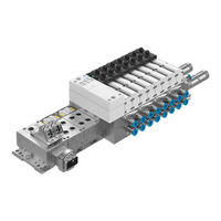
Festo VTSA-F Series Description (267 pages)
Valve terminal with VTSA pneumatics
Brand:
Festo
| Category:
Control Unit
| Size: 5.76 MB
Table of Contents
Overview of Components
18
Intended Use
9
Overview of Components
17
Table of Contents
18
Overview of Components
19
The VTSA
20
Pneumatic Components, Width 18
23
Main and Additional Supply
25
Valves
26
Manifold Sub-Bases
29
Pilot Control
29
Pressure Zone Separation
33
Vertical Stacking
34
Pressure Regulator Plates
38
Components for Protective Functions
44
Manifold Sub-Base VABF-S4
48
Pneumatic Components, Width 65 MM
49
Valves
50
Manifold Sub-Bases
51
Pilot Control
52
Vertical Stacking
52
Connection and Control Elements of the Pneu. Components, Width 18
54
Connection, Display and Operating Elements of the Pneu
58
Components, Width 65 MM
58
Electrical Components
60
Vtsa
60
Vtsa
62
VTSA... Valve Terminal with Multi-Pin
62
Connection and Display Components of the Electrical Components
65
Mounting
73
Mounting
74
Mounting
75
General Instructions on Assembly and Dismantling
76
Mounting Variants
77
Mounting/Dismounting on H-Rails
78
Mounting/Dismounting on Walls
82
Mounting/Dismounting the Optional Inscription Label Holder, Width 18
88
Mounting/Dismounting the Optional Manual Override Cover Caps, Width 18
89
Installation
91
Installation
92
Installation
93
Compressed Air Preparation
94
Operation with Unlubricated Compressed Air
94
Operation with Lubricated Compressed Air
94
General Notes on Connecting the Tubing
97
Installing the Tubing
98
Connecting the VTSA
102
Pilot Control, Width 18
102
Venting Pilot Exhaust Air
102
Pilot Air Supply
103
Pilot Control, Width 65 MM
109
Pilot Air Supply
109
Pressure Zone Separation, Width 18
113
Pressure Zone Separation, Width 65 MM
116
Reversibly Operated VTSA
117
Operating the VTSA
118
Operating the VTSA
119
Regulating Valves
119
Setting the Pressure Regulating Valve
120
Vacuum / Low-Pressure Operation
126
Connecting the Pneumatic Lines
128
Connecting the Electric Cables
139
Address Assignment of the Valves
143
Commissioning
149
Commissioning
150
Commissioning
151
General Notes
152
Prior to Commissioning
152
Pressure Build-Up in the Overall Supply
152
Manual Override (MO)
154
Manual Override, Width 18
155
Manual Override, Width 65 MM
156
Checking the Valves and the Valve/Actuator Combination
158
LED Display of the Valves
163
Valves, Width 18
163
Valves, Widths 65 MM
164
Fault Finding
165
Impairments of Function
165
Operating States of the Pneumatic System
166
Conversion and Maintenance
169
Conversion and Maintenance
170
Conversion and Maintenance
171
General Preventive Action
172
Dismantling the Valve Terminal
173
Replacing the Solenoid Coil Fuse, Width 65 MM
175
Replacing Valve Terminal Components
177
Replacing Valves or Cover Plates, Width 18
177
Replacing the Cover Plate with a Valve, Width 65 MM
179
Replacing/Adding Components for Vertical Stacking, Width 18
181
Replacing/Adding Components for Vertical Stacking, Widths 65 MM
186
Replacing the Exhaust Plate or Exhaust Port Cover, Widths 18
187
Replacing the Manifold Sub-Base, Pneumatic Supply Plate or Right End Plate, Widths 18
187
Replacing the Manifold Sub-Base or Right End Plate, Size 65 MM
191
Converting the VTSA
198
Conversion, Pilot Exhaust Air Via Port (12), Widths 18
198
Conversion, Internal or External Pilot Air Supply, Width 18
200
Conversion, Internal or External Pilot Air Supply, Widths 65 MM
201
Conversion, VTSA
204
Conversion, Valve Terminal with 2 Pressure Zones, Widths 65 MM
207
Adding Valve Positions, Widths 18 ... 52 MM
208
Adding Valve Positions, Widths 65 MM
209
Adding a Soft-Start Valve
211
A. Technical Appendix
213
A.1 Technical Data
215
A.2 Accessories
240
B. Supplementary Overview of Components
244
C. Index
260
Advertisement
Festo VTSA-F Series Description Pneumatics (256 pages)
Valve Terminal
Brand:
Festo
| Category:
Terminal Block
| Size: 4.12 MB
Table of Contents
Table of Contents
5
Intended Use
9
Range of Application and Certifications
9
Target Group
10
Service
10
Notes on this Description
11
Important User Information
12
Overview of Components
17
The VTSA/VTSA-F Valve Terminal
20
Components, Width 18
24
Main and Additional Supply
26
Valves
27
Manifold Sub-Bases
30
Pilot Control
31
Pressure Zone Separation
34
Vertical Stacking
35
Pressure Regulator Plates
39
Components for Protective Functions
46
Vacuum Block VABF-S4-1-V2B1
50
Pilot Air Switching Function (Manifold Sub-Base VABF-S4
51
Components, Width 65 MM
52
Valves
53
Manifold Sub-Bases
54
Pressure Zones
55
Vertical Stacking
55
Connection and Control Elements of the Pneu. Components, Width 18
57
Connection, Display and Control Elements of the Pneumatic Components, Width 65 MM
61
Electrical Components
63
VTSA/VTSA-F Valve Terminal with Multi-Pin Plug
65
Connection and Display Components of the Electrical Components
68
Assembly
75
Assembly
76
Assembly
77
General Instructions on Mounting and Dismantling
78
Mounting Variants
79
Mounting/Dismantling the Optional Inscription Label Holder, Width 18
80
Mounting/Dismantling the Optional Manual Override Cover Caps, Width 18
81
Installation
85
Installation
86
Installation
87
Compressed Air Preparation
88
Operation with Unlubricated Compressed Air
88
Operation with Lubricated Compressed Air
89
General Notes on Connecting the Tubing
92
Installing the Tubing
93
Connecting the VTSA/VTSA-F Valve Terminal
97
Pilot Control, Width 18
97
Venting Pilot Exhaust Air
97
Pilot Air Supply
99
Pilot Control, Width 65 MM
104
Pilot Air Supply
104
Pressure Zone Separation, Width 18
107
Pressure Zone Separation, Width 65 MM
110
Reversibly Operated VTSA/VTSA-F Valve Terminal
111
Operating the VTSA/VTSA-F Valve Terminal with Reversible Valves
112
Operating the VTSA/VTSA-F Valve Terminal with Reversible Pressure Regulators
113
Vacuum / Low-Pressure Operation
119
Connecting the Pneumatic Lines
121
Connecting the Electric Cables
131
Address Assignment of the Valves
135
Commissioning
139
Commissioning
140
Commissioning
141
General Instructions
142
Prior to Commissioning
142
Pressure Build-Up in the Overall Supply
142
Manual Override (MO)
144
Manual Override, Width 18
144
Manual Override, Width 65 MM
145
Manual Override, Width 18 ... 52Mm
145
Manual Override, Width 65 MM
146
Checking the Valves and the Valve/Actuator Combination
148
LED Display of the Valves
153
Valves, Width 18
153
Valves, Widths 65 MM
155
Fault Finding
156
Impairments of Function
156
Operating States of the Pneumatic System
157
Conversion and Maintenance
159
Conversion and Maintenance
160
Conversion and Maintenance
161
General Preventive Action
162
Service and Maintenance Measures to be Executed Regularly
163
Dismantling the Valve Terminal
164
Replacing the Solenoid Coil Fuse, Width 65 MM
166
Replacing Valve Terminal Components
168
Replacing Valves or Cover Plates, Width 18
168
Replacing the Cover Plate with a Valve, Width 65 MM
170
Replacing/Adding Components for Vertical Stacking, Width 18
172
Replacing/Adding Components for Vertical Stacking, Widths 65 MM
177
Replacing the Exhaust Plate or Exhaust Port Cover, Widths 18
178
Replacing the Manifold Sub-Base, Pneumatic Supply Plate or Right End Plate, Widths 18
178
Replacing the Manifold Sub-Base or Right End Plate, Size 65 MM
182
Converting the VTSA/VTSA-F Valve Terminal
189
Conversion, Pilot Exhaust Air Via Port (12), Widths 18
189
Conversion, Internal or External Pilot Air Supply, Width 18
191
Conversion, Internal or External Pilot Air Supply, Widths 65 MM
192
Conversion, VTSA/VTSA-F Valve Terminal with Two or more Pressure Zones, Width 18
194
Conversion, Valve Terminal with 2 Pressure Zones, Widths 65 MM
197
Adding Valve Positions, Widths 18
198
Adding Valve Positions, Widths 65 MM
199
Adding a Soft-Start Valve
201
A. Technical Appendix
203
A.1 Technical Data
205
A.2 Accessories
228
B. Supplementary Component Overview
229
B.1 Overview of Valve Position Components
231
B.2 Separating the VTSA/VTSA-F Valve Terminal from the CPX Terminal
242
C. Index
248
Festo VTSA-F Series Description (208 pages)
Valve terminal with VTSA pneumatics
Brand:
Festo
| Category:
Industrial Electrical
| Size: 5.53 MB
Table of Contents
Table of Contents
5
Intended Use
9
Range of Application and Certifications
9
Target Group
10
Service
10
Notes on the Use of this Manual
11
Important User Instructions
12
Overview of Components
17
The VTSA
20
Overview of Variants
21
Description of Components
25
Installation
78
Installation
79
Compressed Air Preparation
80
Operation with Unlubricated Compressed Air
80
Operation with Lubricated Compressed Air
80
General Connection Technology
83
Installing the Tubing
84
Connecting the VTSA
87
Ducted Exhaust of Control Air and Venting Air
87
Pilot Control (Pilot Air Supply)
88
Vtsa
94
Reversibly Operated VTSA
97
Operating the VTSA
98
Operating the VTSA
99
Setting the Pressure Regulating Valves
100
Vacuum/Low Pressure Operation
103
Connecting the Pneumatic Lines
105
Connecting the Electric Cables
112
Address Assignment of the Valves
115
Commissioning
120
Commissioning
121
General Information
122
Before Commissioning
122
Pressure Build−Up in the Overall Supply
122
Manual Override
124
Checking the Valves and the Valve/Actuator Combination
126
Troubleshooting
133
Malfunctions
133
Operating States of the Pneumatic System
134
Maintenance and Conversion
136
Maintenance and Conversion
137
General Preventive Action
138
Dismantling the Valve Terminal
139
Replacing Valve Terminal Components
141
Replacing Valves or Cover Plates
141
Replacing/Adding Components for Vertical Stacking
143
Replace the Exhaust Plate or the Exhaust Port Cover
148
Replace the Manifold Sub−Base, the Pneumatic Supply Plate or the Right−Hand End Plate
148
Converting the VTSA
152
Conversion to Ducted Pilot Exhaust and Venting Air
152
Conversion to Internal or External Pilot Air Supply
153
Conversion of the VTSA
154
Advertisement
Festo VTSA-F Series Manual (176 pages)
Valve terminal with VTSA pneumatics
Brand:
Festo
| Category:
Industrial Equipment
| Size: 5.28 MB
Table of Contents
Table of Contents
5
Intended Use
9
Target Group
9
Service
9
Notes on the Use of this Manual
10
Important User Instructions
12
1 Overview of Components
17
The VTSA
20
Overview of Variants
20
Description of Components
23
2 Mounting
47
Mounting
48
Mounting
49
General Instructions on Fitting and Dismantling
50
Fitting Variants
51
Fitting Onto/Removing from a hat Rail
52
Fitting Onto/Removing from a hat Rail
56
Fitting/Removing the Inscription Label Holder (Optional)
59
Fitting/Removing the Manual Override Caps (Optional)
60
Installation
64
Installation
65
Vtsa
65
Reversible 2X3/2−Way Valves
65
Operating the VTSA
80
Reversible Pressure Regulators
80
Setting the Pressure Regulator
82
Vacuum/Low Pressure Operation
85
Connecting the Pneumatic Tubing
86
Connecting the Electric Cables
91
Address Assignmentof the Valves
94
Conversion and Maintenance
114
Conversion and Maintenance
115
General Precautionary Measures
116
Dismantling the MPA Valve Terminal
117
Replacing Valve Terminal Components
119
Replacing Valves or Cover Plates
119
Replacing/Adding Components for Vertical Stacking
121
Replace the Exhaust Plate or the Exhaust Cover
126
Replace the Manifold Sub−Base, the Pneumatic Supply Plate or the Right−Hand End Plate
126
Converting the VTSA
130
Conversion to Ducted Pilot and Breathable Exhaust Air
130
Conversion of the VTSA
132
Adding Valve Locations
135
Advertisement
Related Products
Festo VTSA Series
Festo VIFB9-02 Series
Festo VIFB-02-1/4-10
Festo VIFB-02-1/4-16
Festo VIFB-02-1/8-4
Festo VIFB-02-1/8-6
Festo VIFB-02-1/8-8
Festo VMPA-KMS2-8 Series
Festo VMPA-KMS1-24 Series
Festo VMPA-KMS2-24 Series
Festo Categories
Industrial Equipment
Control Unit
Controller
Touch terminals
DC Drives
More Festo Manuals
Login
Sign In
OR
Sign in with Facebook
Sign in with Google
Upload manual
Upload from disk
Upload from URL