Table of Contents
Advertisement
Quick Links
SKF Multilog On-line
System WVT
CMWA 7910
User Manual Part No. 32311900-EN
Revision A
WARNING! Read this manual before using this product. Failure to follow the
instructions and safety precautions in this manual can result in serious injury,
damage to the product, or incorrect readings. Keep this manual in a safe location
for future reference.
Copyright 2015 by SKF USA Inc.
All rights reserved.
5271 Viewridge Court., San Diego, CA 92123-1841 USA
Telephone: (858) 496-3400, Fax: (858) 496-3531
Customer Service: 1-800-523-7514
User manual
Advertisement
Table of Contents

Related Manuals for SKF On-line System WVT


Summary of Contents for SKF On-line System WVT
- Page 1 Keep this manual in a safe location for future reference. Copyright 2015 by SKF USA Inc. All rights reserved. 5271 Viewridge Court., San Diego, CA 92123-1841 USA...
- Page 2 SKF reserves the right to alter any part of this publication without prior notice.
- Page 3 (30) days of discovery of the nonconformity; provided, however, that SKF shall not be liable and accessories. for any claim for which notice is received by SKF TWO-YEAR WARRANTY more than thirty (30) days following the expiration of the applicable warranty period for Products warranted for two (2) years by SKF the Product.
- Page 4 Limited Lifetime Warranty during the of SKF-supplied or SKF-approved devices and/or components. The computer provided by life of such products, SKF USA Inc., in its Buyer must meet the requirements stipulated sole discretion, will repair, replace or exchange the products for the same model by SKF.
- Page 5 Limited Lifetime Warranty shall not exceed the purchase writing by SKF, Buyer shall forward to SKF any price of the product, plus any shipping and Product claimed by Buyer as being defective.
- Page 6 INFRINGEMENT; TO THE SALE OF ANY PRODUCT BY SKF TO THE FURTHEST EXTENT PERMITTED BY APPLICABLE LAW. (B) IN NO EVENT SHALL SKF BE LIABLE OR OBLIGATED FOR SPECIAL, EXEMPLARY, The exclusive remedies provided in this limited PUNITIVE, INCIDENTAL, DIRECT,...
- Page 7 “Agreement”) is entered into by and between SKF USA Inc. and/or SKF Condition Monitoring trust, a joint venture, an Center AB (hereinafter referred to collectively as unincorporated organization, or a governmental entity (or any the “Licensor”) and any person or business that...
- Page 8 Software for Wireless forth more particularly in the Monitoring System V/T, SKF @ptitude applicable purchase order or other ordering documents Analyst, SKF @ptitude Inspector, SKF @ptitude Observer, SKF @ptitude memorializing your license acquisition;...
- Page 9 SQL Server license, or if the Licensee (vii) make the Software accessible to any Person by any means, fails to install such database software, the Software will not work. including posting on a web site or through other distribution Licensee is responsible for maintaining a valid database license mechanisms over the Internet;...
- Page 10 use the Software to promote valuable copyright and contains valuable trade secrets of Licensor. pornography, hatred, or racism. Licensee agrees not to discover or attempt to discover, or assist or Copies. Licensee, solely to enable it permit any Person to discover or to use the Software, may make one attempt to discover, by any means whatsoever the source code of the...
- Page 11 Licensor Audit Rights, terminate this Agreement and the license granted hereunder including, without limitation, all attorneys’ fees and agent immediately and without an opportunity to cure. This subsection fees incurred by Licensor. If Licensor concludes that no 2(j) shall not be construed to preclude, violation of this License or in any way effect, a finding of materiality with respect to any other...
- Page 12 programs described in the PSP literature or Licensor aware of any defect with the Software within seven (7) days after other material from Licensor’s Product Support Department (hereinafter referred the occurrence of the defect; (ii) Licensee has paid all amounts due to as the “PSP Policies”) that may be updated by Licensor from time to time.
- Page 13 8. LIMITATIONS ON LIABILITY 9. TERM AND TERMINATION Limitations and Exclusions. IN NO Term. This Agreement shall EVENT WILL LICENSOR BE LIABLE commence on the Effective Date and TO LICENSEE FOR ANY DIRECT, shall continue in existence until it is INDIRECT, INCIDENTAL, terminated in accordance with Section CONSEQUENTIAL, PUNITIVE OR...
- Page 14 any act of God, any acts of the common such Party’s respective address shall be effective service of process for any Legal enemy, the elements, earthquakes, floods, fires, epidemics, riots, failures or delay in Proceeding. Licensor and Licensee irrevocably and unconditionally waive any transportation or communications;...
- Page 15 (d) Severability. If any provision of this Support or any other software within the Agreement is invalid, illegal or SKF @ptitude family suite and the trade unenforceable under any applicable dress, logos and other designations of statute or rule of law, it is to that source used by Licensor to identify the extent to be deemed omitted.
- Page 16 substantial and inadequate to compensate Licensor. Consequently, Licensor shall be entitled to seek and obtain, in addition to such other monetary relief as may be recoverable at law or in equity, such injunctive other equitable relief as may be necessary to restrain any threatened, continuing, or further breach by Licensee without showing or proving actual damages sustained...
-
Page 17: Table Of Contents
System Overview Safety Messages ............1-1 About This User Manual ........... 1-3 Technical Support ............. 1-4 SKF Multilog WVT System Overview ...... 1-4 Hardware and Network Requirements ....1-6 Software Requirements ........... 1-7 Network Data Flow ........... 1-8 OneWireless Terminology ........1-10 User Manual Outline .......... - Page 18 Chapter Summary ............. 8-9 Configuring the XML Import Configuring the XML Import in SKF @ptitude Analyst ..............9-1 SKF Multilog WVT in the SKF @ptitude Analyst Hierarchy ..............9-4 SKF @ptitude Analyst Transaction Service ... 9-5 SKF @ptitude Analyst Database Maintenance ..9-8 Chapter Summary .............
- Page 19 Vibration Sensor Mounting ........A-1 Sensor Installation Instructions ....... A-2 Mounting Pad and Sensor Installation Instructions ............. A-4 Speed Sensor / Namur Tachometer Installation Instructions ............. A-6 The Sensor Mounting Toolkit ........A-8 SKF Multilog On-line System WVT TOC - 3 User Manual...
-
Page 21: System Overview
Patent Information This product is covered by patents owned or licensed by SKF USA Inc. and is intended for use only with components authorized by SKF. Any use of this product in combination with other components not purchased from SKF may subject the user to liability for patent infringement. - Page 22 Do not operate the equipment without the antenna connected. Device service must be performed only by qualified SKF repair personnel. Use only accessories recommended or provided by SKF USA Inc. or the manufacturer. Energized Equipment Never work on energized equipment unless authorized by a responsible authority.
-
Page 23: About This User Manual
This user manual provides technical information about the SKF Multilog On-line System WVT device (WVT stands for Wireless Vibration Transmitter), commonly called the “SKF Multilog WVT” in this user manual. This user manual also helps you to set up the SKF ∗... -
Page 24: Technical Support
SKF Multilog WVT System Overview The SKF Multilog On-line System WVT (SKF Multilog WVT) unit is a compact, four- channel vibration and temperature field-mounted monitoring device that communicates on the ISA100.11a wireless standard. - Page 25 System Overview SKF Multilog WVT System Overview Figure 1 – 1. System Components: Hardware and Basic Network. SKF Multilog On-line System WVT 1 - 5 User Manual...
-
Page 26: Hardware And Network Requirements
Provisioning Device (optional) – If over-the-air provisioning is not used, a provisioning device will be required for providing the SKF Multilog WVT with security keys from the WDM. The provisioning device is a handheld PDA unit with an Infrared Data Association (IrDA) port that communicates with the IrDA port on the SKF Multilog WVT unit. -
Page 27: Software Requirements
European Telecommunications Standards Institute (ETSI). The data acquisition section of the SKF Multilog WVT acquires samples according to the downloaded configurations at a user defined interval. Each SKF Multilog WVT automatically publishes trend measurements through the network. The trace measurements are, however, required to be directly uploaded by the software from the SKF Multilog WVT according to the user defined schedule. -
Page 28: Network Data Flow
Microsoft .NET Framework 4 is required for the DataController application Network Data Flow In a typical industrial plant, the SKF Multilog WVTs can be spread across multiple WDMs and multiple ISA100 networks due to their physical location. Each WDM can communicate with up to 30 SKF Multilog WVT devices (if the network is exclusively SKF Multilog WVTs). - Page 29 System Overview Network Data Flow Figure 1 - 2. Network Data Flow Diagram. SKF Multilog On-line System WVT 1 - 9 User Manual...
-
Page 30: Onewireless Terminology
–xx and –yy is less than 5, the lowest of the two values is displayed. HART Highway Addressable Remote Transducer Gateway Client Interface Transmit Fail Ratio. TxFailRatio TxFailRatio = Transmit Fail / (Transmit Success + Transmit Fail) 1 - 10 SKF Multilog On-line System WVT User Manual... -
Page 31: User Manual Outline
WDM and PCN network properties, and upload the Device Description file to the WDM. Chapter 5, Setting Up the SKF Multilog WVT – presents the setup procedure, how to commission the device, and how to mount the device and remote antenna. - Page 32 System Overview SKF Multilog WVT Maintenance • Upgrading the SKF Multilog WVT application firmware • Upgrading the SKF Multilog WVT radio firmware • Changing the Trend Sampling Interval • Changing the Trace Sampling Interval 1 - 12 SKF Multilog On-line System WVT...
-
Page 33: Hardware Overview
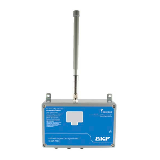
Hardware Overview Included Items On receipt, you will find the following items in the SKF Multilog WVT carton: • The SKF Multilog On-line System WVT unit • External omnidirectional antenna • Gland position blanking plugs • Spare screws and fittings •... - Page 34 LCD display push button for LCD display Figure 2 – 1. SKF Multilog WVT External View. Antenna The SKF Multilog WVT uses an omnidirectional, rugged, lightweight and waterproof antenna. Specifications are: Frequency: 2 400 to 2 485 MHz Gain: 5 dBi...
-
Page 35: Internal Overview
Internal Overview Analog Input Signals The SKF Multilog WVT has four pairs of channel inputs, each pair comprising a dynamic accelerometer input and a process temperature input. It is designed to operate with low-power dual output sensors which provide a dynamic vibration signal and a static temperature signal. - Page 36 Remove jumper and insert ammeter to measure Radio Inserted current to analog radio. Can also be used to power Current cycle radio independently. 2 - 4 SKF Multilog On-line System WVT User Manual...
- Page 37 Internal Overview Display The display on the front shows the status of the SKF Multilog WVT. You can interrogate the unit at any time by pressing the display push button on the right side of the unit. On pressing the push button, the backlight is illuminated for five seconds and subsequent presses will scroll through three screens.
- Page 38 Another screen is used during device commissioning. Device commissioning allows the SKF Multilog WVT to be tested independently of the network. This is useful to check the connection of the sensors and the tacho device after they are connected to the SKF Multilog WVT.
-
Page 39: Restoring Factory Defaults
After the five second countdown, a message states: Device Defaults Being Reset. Figure 2 – 7. Device Defaults Being Reset Message. The SKF Multilog WVT will lose network connection after being returned to factory defaults. It will have to be reprovisioned to rejoin. -
Page 40: Connections
It is not necessary to connect the temperature input if it is not needed. Note that there is no cable shield grounding inside the SKF Multilog WVT. The shield of the CMSS 2350 sensor cable, CMAC 2350-CABLE-xxM (xxM indicates the cable length in meters), is grounded at the sensor side. - Page 41 1 mA nominal current when a target is present. An example of an embedded sensor with 5 mm range is NCB5-18GM40-NO-V1. There are a number of options for embedded, non-embedded, with and without integral cable. SKF Multilog On-line System WVT 2 - 9 User Manual...
-
Page 42: Installation Torque
6 V with built-in power limiting. The Namur sensor is specified to operate down to a voltage of 5 V. The SKF Multilog WVT senses the change in current from 3 to 1 mA when a metal target is within the sensitivity range. -
Page 43: Battery Replacement
WARNING! The battery level reading resets to 100% after the batteries are removed from the holder. You can check the battery level of the SKF Multilog WVT in the WDM user interface by going to Device Vendor Parameters > Device Power > Battery Level. -
Page 44: Battery Conservation
Then, the battery holder with expended batteries can be removed from the SKF Multilog WVT to be replaced with the additional battery holder already loaded with fresh batteries. -
Page 45: Events Affecting Battery Life
Hardware Overview Events Affecting Battery Life Events Affecting Battery Life The following table summarizes some common events and their impact on the expected life of the batteries in the SKF Multilog WVT. Event (Cause) Result Actions High Impact Battery powered SKF Multilog... - Page 46 0.4% battery life lost Storing the SKF Multilog WVT Because the unit does not turn off, if you remove a battery powered SKF Multilog WVT from the network for storage, it will continue to search for the network. To conserve battery power and preserve the battery level, be sure to flip the power switch PWR to the EXT position.
-
Page 47: Specifications Of Skf Multilog Wvt
(SKF enveloped acceleration filter 3) Averages 1 to 4, 50% overlap, spectral domain only Processor ARM9, ultra-low power Non-volatile RAM 512 kB Internal real-time clock Watchdog function Automatic recovery on power interruption SKF Multilog On-line System WVT 2 - 15 User Manual... - Page 48 Communications Radio 11 dBm, antenna 5 dBm, range 300 m (984 ft.) Commission/Industry Canada) ETSI (European Telecommunications Radio 4 dBm, antenna 5 dBm, range 100 m (328 ft.) Standards Institute) 2 - 16 SKF Multilog On-line System WVT User Manual...
- Page 49 Time waveform (data Velocity spectrum (400 Up to 5 years Overall velocity block lengths: 2 048) lines) Enveloped Acceleration Overall Enveloped spectrum (800 lines) Acceleration Bias voltage check Temperature Tacho speed SKF Multilog On-line System WVT 2 - 17 User Manual...
-
Page 50: Specifications Of Cmss 2350T-D2 Sensor
–40 to +120 °C (–40 to +250 °F) operating temperature Temperature range Vibration limit 500 g peak Shock limit 5 000 g peak Hermetic Sealing Base strain 200 µg/µstrain sensitivity, maximum 2 - 18 SKF Multilog On-line System WVT User Manual... - Page 51 CMAC 2350-CABLE-20M cable 20 m (65.6 ft.) cable with M12 4-pin non-isolated connector Agency Approvals • CE approved • CSA: – Class I, Division 2, Groups A, B, C and D SKF Multilog On-line System WVT 2 - 19 User Manual...
- Page 52 Specifications of CMSS 2350T-D2 Sensor Dimensions of CMSS 2350T-D2 Sensor Figure 2 –8. CMSS 2350T-D2 Sensor Dimensions. See Appendix A, Installing the Sensors in this user manual for detailed procedures of the physical installation. 2 - 20 SKF Multilog On-line System WVT User Manual...
-
Page 53: System Setup Checklist
System Setup Checklist Setup Checklist The checklist below provides a general guideline to follow when setting up the SKF Multilog WVT system in a OneWireless network. For brevity, in this checklist DataController is called “DC” and SKF @ptitude Analyst is called “Analyst.”... -
Page 55: Setting Up The Network
Configure the WDMs to communicate through the PCN IP address with the Local Area Network (LAN). At the end of this chapter, we will also present the procedure for uploading the SKF Multilog WVT Device Description file to the WDM. At that point, the network will be ready and operational for the SKF Multilog WVT devices to be set up and join the network. -
Page 56: Network Planning Considerations
40 minutes (1 hop) to 4 hours The maximum number of SKF Multilog WVTs for each of the routing devices in the table above are accumulative. For example, with two wireless FDAPs that each support the maximum of seven SKF Multilog WVTs, the wired access point could support an additional single wireless SKF Multilog WVT (7+7+1=15). - Page 57 For example: The user detects an alert and decides to increase the configurations and schedules on four channels of an SKF Multilog WVT. The user is allowed to increase the settings to the following configuration values for any of the two SKF Multilog WVT units (but not more than two SKF Multilog WVT units) under any access point or routing device.
-
Page 58: Connecting The Network Components
SKF Multilog WVT. Make sure that you have the Ethernet cables required for connecting the devices. Mount the SKF Multilog WVT at least 2 m (6.5 ft.) away from the nearest network component with an antenna. To establish physical connection between the components: •... - Page 59 IMPORTANT: When powering up the WDM, if a duplicate IP address is configured either on the PCN port or the FDN port, the WDM startup operation ends. To recover, you must resolve the duplicate IP address from the network. SKF Multilog On-line System WVT 4 - 5 User Manual...
-
Page 60: Configuring The Wdm, Pcn And Fdn Network Properties
Configure the IP address as 192.168.1.x and Subnet Mask as 255.255.255.0. Do not configure the computer with the default IP address of the WDM, 192.168.1.1. • Click OK to close the Properties dialog. 4 - 6 SKF Multilog On-line System WVT User Manual... - Page 61 A copy of Silverlight is maintained on the WDM for installs and upgrades; no Internet or external connection is required. If you have connected to the FDN side of the network, enter the default IP address: https://192.168.0.1. SKF Multilog On-line System WVT 4 - 7 User Manual...
- Page 62 Figure 4 - 6. User Login Dialog. • In the Password field, enter the default of password. Note that the Password field is case-sensitive. Click Login to launch the WDM’s web page. • 4 - 8 SKF Multilog On-line System WVT User Manual...
- Page 63 WDM. • Click the white arrow next to Process Control Network (PCN) on the Property Panel. The Process Control Network (PCN) section will open. SKF Multilog On-line System WVT 4 - 9 User Manual...
- Page 64 WDM. • Click the white arrow next to Field Device Network (FDN) on the Property Panel. The Field Device Network (FDN) section will open. 4 - 10 SKF Multilog On-line System WVT User Manual...
- Page 65 You can now disconnect the WDM from the configuring PC and communicate directly through the LAN. Next, you are ready to upload the Device Description file to the WDM. SKF Multilog On-line System WVT 4 - 11 User Manual...
-
Page 66: Uploading The Device Description File
The Device Description (DD) file is a .ZIP file which is available on the product CD supplied by SKF. The Device Description file for the SKF Multilog WVT is needed by the WDM to understand the device and channel parameters. The Device Description file contains: •... -
Page 67: Chapter Summary
Click Close to close the Upload DD dialog. If the Data Description file is not uploaded to the WDM when an SKF Multilog WVT device joins the network, then the WDM will select a default Data Description file for the device and you will not see an error message. - Page 68 Configured the WDM to communicate through the FDN IP address. • Uploaded the SKF Multilog WVT Device Description file to the WDM. At this point, the network will be operational. In the next chapter, we will set up the SKF Multilog WVT device. 4 - 14...
-
Page 69: Setting Up The Skf Multilog Wvt
Chapter Overview In this chapter, we will present the steps required to prepare and commission the SKF Multilog WVT unit and its sensors. Also provided are instructions for mounting the SKF Multilog WVT unit and remotely mounting the antenna (optional). - Page 70 Connect the tacho as shown, using either the Namur or the isolated connector. • Connect each sensor to the SKF Multilog WVT sensor inputs for the appropriate channel. As shown below, the order of the wire colors for each channel, from left to right, are: –...
- Page 71 Setting Up the SKF Multilog WVT The Setup Procedure Figure 5 - 2. Vibration / Temperature Dual Sensor Wiring. The compatible sensor cable options include: • CMAC 2350-CABLE-5M, 5 m (16.4 ft.) cable with M12 4-pin non-isolated connector • CMAC 2350-CABLE-10M, 10 m (32.8 ft.) cable with M12 4-pin non-isolated connector •...
-
Page 72: Cmwa 7910 Installation Drawing No. G14/0361 For Externally Powered Installations
Setting Up the SKF Multilog WVT CMWA 7910 Installation Drawing No. G14/0361 for Externally Powered Installations CMWA 7910 Installation Drawing No. G14/0361 for Externally Powered Installations Figure 5 - 3. CMWA 7910 Installation Drawing No. G14/0361 for Externally Powered Installations. - Page 73 Setting Up the SKF Multilog WVT CMWA 7910 Installation Drawing No. G14/0361 for Externally Powered Installations General Installation Notes 1. This unit may be powered from an external power source in the range 10-30 VDC. These notes refer to installations where the device is powered from an external power supply.
-
Page 74: Cmwa 7910 Installation Drawing No. G14/0360 For Battery Powered Installations
Setting Up the SKF Multilog WVT CMWA 7910 Installation Drawing No. G14/0360 for Battery Powered Installations CMWA 7910 Installation Drawing No. G14/0360 for Battery Powered Installations Figure 5 - 4. CMWA 7910 Installation Drawing No. G14/0360 for Battery Powered Installations. - Page 75 Setting Up the SKF Multilog WVT CMWA 7910 Installation Drawing No. G14/0360 for Battery Powered Installations General Installation Notes 1. This unit may be powered from internally fitted batteries. When using internal batteries, no connection should be made to the external power input. These notes refer to installations where the device is powered from internal batteries.
-
Page 76: Commissioning Mode
To put the SKF Multilog WVT into Commissioning Mode, insert a jumper into position JP2 on the left side of the main board, and then press the LCD display push button on the outside of the unit. -
Page 77: Mounting And Dimensions
Figure 5 - 6. SKF Multilog WVT Dimensions. WARNING! Mount the SKF Multilog WVT at least 2 m (6.5 ft.) away from the nearest SKF Multilog WVT or FDAP. Mounting the units too close together may result in dropped network links or possible failure of the radio card. -
Page 78: Mounting The External Antenna
Mounting the External Antenna The antenna can be mounted remotely with an additional coaxial cable (sold separately) and the optional SKF Remote Antenna Mounting Kit P/N CMAC 7820-MK, or your own hardware. Additional coaxial cables are available in three different lengths: 1 m (3.3 ft.) P/N CMAC 7820-EXTCBL-1M... - Page 79 Setting Up the SKF Multilog WVT Mounting the External Antenna Figure 5 - 8. External Antenna Mounted to Pole. WARNING! EXPLOSION HAZARD! Connection and disconnection of cables and antennas may cause a spark that can ignite a potentially explosive atmosphere.
- Page 80 Setting Up the SKF Multilog WVT Mounting the External Antenna Figure 5 - 9. Antenna Installation Diagram. To remotely mount the external antenna: • Connect the external antenna plug connector to the N jack connector on the coaxial cable selected (1 m, 3 m or 10 m in length).
- Page 81 You may follow with electrical tape for additional protection, as described above. WARNING! After commissioning, remove power to the SKF Multilog WVT and do not apply power until it is time to provision the device into active service in the network.
-
Page 82: Chapter Summary
• Mounted the SKF Multilog WVT device. At this point, DataController must be installed to configure the SKF Multilog WVT devices before they join the network; refer to Chapter 6, DataController Installation, and Chapter 7, DataController and XML File Editor, of this user manual. -
Page 83: Datacontroller Installation
• XML File Editor – This user interface enables the editing of three XML files critical to the operations of the SKF Multilog WVT. This is discussed in detail in the next chapter of this user manual. • Service Manager – This is the user interface that starts and stops the Windows service application that runs in the background. -
Page 84: Datacontroller Prerequisites
DataController Installation DataController Prerequisites • Collects time wave and spectrum data from all four channels of SKF Multilog WVT devices at user-configured periods for all the possible measurements: acceleration, velocity and bearing. • Collects trend values (or Process Value, PV) from all four channels of SKF Multilog WVT devices at user-configured periods for all the possible measurements: acceleration, velocity, bearing, speed, bias voltage and temperature. -
Page 85: Installing Datacontroller
The Welcome to the DataController Setup Wizard appears. Figure 6 - 1. DataController Icon. Figure 6 - 2. DataController Setup Wizard – Welcome Window. • Click Next. The Select Installation Folder window appears. SKF Multilog On-line System WVT 6 - 3 User Manual... - Page 86 Click Next. The Confirm Installation window appears. Figure 6 - 4. DataController Setup Wizard – Confirm Installation Window. • Click Next. The Installing DataController window appears very briefly, showing the progress of the installation process. 6 - 4 SKF Multilog On-line System WVT User Manual...
- Page 87 • Windows service. Go to Start > Control Panel > Administrative Tools > Services to check for DataController in the list. Figure 6 - 6. DataController in the Services List. SKF Multilog On-line System WVT 6 - 5 User Manual...
-
Page 88: Launching Servicemanager
To launch ServiceManager: • You can start and stop the DataController service by using the Service Manager shortcut present on Windows Start menu. Go to SKF > DataController on the Windows Start menu and click ServiceManager. Figure 6 - 7. - Page 89 If modifications are made to the global configuration parameters or the data collection schedule after the SKF Multilog WVT device is in operation, the new settings will not become effective until the DataController service has been stopped and restarted.
-
Page 90: Removing Datacontroller
The Add or Remove Programs dialog displays for you to confirm the removal. Click Yes. Figure 6 - 12. Add or Remove Programs Dialog. The Uninstalling DataController dialog opens to display the progress. You may still cancel the action at this point. 6 - 8 SKF Multilog On-line System WVT User Manual... -
Page 91: Chapter Summary
Launched Service Manager and confirmed the service is running. • Seen how to remove DataController. In the next chapter we will use XML File Editor in DataController to configure the SKF Multilog WVT. SKF Multilog On-line System WVT 6 - 9... -
Page 93: Datacontroller And Xml File Editor
The file SpectrumCollectNvs.xml is created later when the SKF Multilog WVT has taken data. The default path is C:\Temp\DataController\Config. Launching XML File Editor You will launch XML File Editor to perform the initial configuration of the SKF Multilog WVT. WARNING! DataController works only in administrator mode in Windows 7 unless you are running in XP compatible mode. -
Page 94: Wdmlist
IMPORTANT: The IP address and TCP Port entered in WDMList must match exactly the PCN IP address and the the Gateway Client Interface Server TCP Port in the WDM configuration. Figure 7 - 2. WDMList Tab. 7 - 2 SKF Multilog On-line System WVT User Manual... - Page 95 To find the WDM’s TCP Port, go to the WDM user interface web page and expand the WDM item to select GCI. Figure 7 - 4. WDM Expanded, GCI Communication Port. When you open Configuration in the Property Panel, the TCP Port will be displayed. SKF Multilog On-line System WVT 7 - 3 User Manual...
-
Page 96: Global Configuration (Globalconfig)
DataController will load these settings automatically on factory default state devices. If you want to re-initialize the SKF Multilog WVT with the current global configuration, first you will have to reset the SKF Multilog WVT to its factory default settings. Refer to Chapter 2, Hardware Overview,... - Page 97 Click the SelectFile button at the bottom of the tab to locate and open the desired GlobalConfig.xml file to define the global default SKF Multilog WVT configuration. Edits made within the tab will update the selected xml file. Again, the message “File Parse Success”...
- Page 98 16 MB limit, it will be renamed to DataControllerLog.txt.1 file and a new DataControllerLog.txt file will be created. Each succeeding time the DataControllerLog.txt file exceeds allowed storage space, the file names will 7 - 6 SKF Multilog On-line System WVT User Manual...
- Page 99 In DataFolder, define the directory path where the Data XML files (POINTs/Data/ Events) are created by DataController and are consumed by SKF @ptitude Analyst. This must match exactly the Input directory in the SKF @ptitude Analyst XML Import Configuration dialog, as stated in Chapter 9, Configuring the XML Import.
- Page 100 DataController trace collection schedule which is displayed initially in the SpectraDownload and Time+SpectraDownload fields in the GlobalConfig tab. These can be modified for an individual SKF Multilog WVT unit in the SpectrumCollectNvs file. To enter the Device Settings: •...
- Page 101 Select the TraceWakeUp interval in number of minutes, hours, or days, up to one month, in between the times when the SKF Multilog WVT will take the specified time wave and spectra measurements. The options for the TraceWakeUp interval are the same as TrendWakeUp interval.
- Page 102 Select the AccSpectrumScale. Peak is the default setting for the acceleration spectrum. Peak is calculated from RMS. Select the VelSpectrumScale. RMS (root-mean-squared) is the default setting for • the velocity spectrum. 7 - 10 SKF Multilog On-line System WVT User Manual...
- Page 103 • Select the BeaSpectrumScale. Peak To Peak is the default setting for the bearing spectrum. (SKF uses Peak to Peak for the bearing spectrum scale.) Channel Settings – Trace Field Settings The lower half of the GlobalConfig tab displays the Channel Settings.
- Page 104 SKF @ptitude Analyst for line powered versus battery powered SKF Multilog WVT devices. It also shows the default trace interval in DataController for line powered versus battery powered SKF Multilog WVT devices in the event that the trace interval value was less than the required data upload time.
- Page 105 For example, with the Trace Interval set to every 15 minutes, you must reduce the number of samples to 256. This will allow the SKF Multilog WVT to complete sending the traces for all four channels to SKF @ptitude Analyst within 15 minutes.
- Page 106 0 RPM. • Select the number of Samples you want the SKF Multilog WVT to take. The number of samples is equal to the number of FFT lines x 2.56. 7 - 14...
- Page 107 Select the number of Averages: 1, 2, 3 or 4. The table above can help you • determine the maximum number of averages to select according to the number of samples and sample rate. • Select the Gain (1 or 10). SKF Multilog On-line System WVT 7 - 15 User Manual...
- Page 108 • Select the SpectraDownload frequency for DataController to collect the FFT. This interval must be greater than the data upload time to SKF @ptitude Analyst, according to the Trace Data Collection Interval Guidelines table presented in the previous section, Time Required for Trace Data to Be Available in SKF @ptitude Analyst.
-
Page 109: Chapter Summary
Port number of each WDM in order to communicate with them over the Ethernet. • Edited the GlobalConfig tab with the user-defined global configuration settings that DataController will load automatically to the SKF Multilog WVT if it comes in factory default state. •... -
Page 111: Datacontroller And The Wdm
ISA100.11a standard. DataController implements a GCI Client interface and the WDM provides a GCI Server interface to communicate with SKF Multilog WVT devices connected over the ISA100 network. After accessing the WDM’s web page, you must configure the GCI Server so that DataController can communicate with the WDM. - Page 112 Figure 8 - 3. Expanded WDM Icon - Select GCI. • On the Property Panel, expand Configuration. Figure 8 - 4. Property Panel – Configuration. In the Interface group, select TCP Interface. • 8 - 2 SKF Multilog On-line System WVT User Manual...
- Page 113 Click the Apply button below the Property Panel to apply the changes. The Apply and Reset buttons become active when you make changes in the Property Panel. Click Reset if you do not want to apply your changes. SKF Multilog On-line System WVT 8 - 3 User Manual...
- Page 114 DataController and the WDM Configuring the GCI Server Figure 8 - 7. Apply the Settings. DataController is now able to communicate with the WDM through the specified TCP Port. 8 - 4 SKF Multilog On-line System WVT User Manual...
-
Page 115: Verifying Datacontroller's Connection To The Wdm
GCI configuration procedure in this chapter and check that the WDM IP address is correct, that TCP Interface is selected as the Interface, and the TCP Port is correct. SKF Multilog On-line System WVT 8 - 5 User Manual... -
Page 116: Verifying The Local Time Zone
The SKF Multilog WVT uses Coordinated Universal Time (UTC) internally. DataController will configure the SKF Multilog WVT device with the local time zone when the device in its factory default state is initialized. With this step complete, DataController will export measurements with the correct date/time stamp. -
Page 117: Configuring The Measurement Units
WARNING! When you make a change to the Units Index for a channel, DataController deletes the corresponding POINTs for that channel in SKF @ptitude Analyst. New POINTs will be created with the new units. - Page 118 To configure the Units Index, Temperature Overall: • Go to the WDM user interface web page. • In the Selection Panel, select the SKF Multilog WVT. • Click Inactivate in the Channel group in the ribbon bar to inactivate all channels at one time.
-
Page 119: Chapter Summary
DataController’s connection to the GCI Server. We have verified the local time zone and configured the SKF Multilog WVT with the desired measurement units. In the next chapter, we will configure SKF @ptitude Analyst to import the DataController output XML files. -
Page 121: Configuring The Xml Import
Configuring the XML Import Configuring the XML Import in SKF @ptitude Analyst SKF @ptitude Analyst must be configured to import the DataController output XML files. Essentially, the Input directory must match DataController’s DataFolder and the File Prefix must be identical in both applications. The general purpose of the XML Import feature is to import data from a third party system. - Page 122 XML files. • Click Browse… to locate and select the Input directory for SKF Multilog WVT data files from DataController. IMPORTANT: The Input directory in the SKF @ptitude Analyst XML Import Configuration must be the same as the DataFolder in the GlobalConfig tab.
- Page 123 In the File Prefix text entry box, enter WVT_ISA100_A_ as the prefix. The file prefix for the SKF Multilog WVT device in the SKF @ptitude Analyst Import Configuration is WVT_ISA100_X_, where X is the same Prefix in the GlobalConfig tab.
-
Page 124: Skf Multilog Wvt In The Skf @Ptitude Analyst Hierarchy
SKF Multilog WVT in the SKF @ptitude Analyst Hierarchy SKF Multilog WVT in the SKF @ptitude Analyst Hierarchy After the SKF Multilog WVT has joined the network and the XML import has been configured, and the DataController service is running in the background, then DataController should create the following items for each SKF Multilog WVT in the SKF @ptitude Analyst hierarchy. -
Page 125: Skf @Ptitude Analyst Transaction Service
It monitors the Input directory for new XML files from DataController at the regular interval as specified in the XML Import Configuration dialog, as described in the previous section. You can verify that the transaction service is running by checking the SKF @ptitude Analyst Configuration Tool. Follow the steps below. •... - Page 126 Figure 9 - 7. SKF @ptitude Analyst Configuration Tool. • Select SKF @ptitude Transaction Service in the left panel. The right panel displays information about the available transaction service entries. • Select the desired service in the list. Multiple actions become available.
- Page 127 Test. Figure 9 - 9. Transaction Server Service Test Result. Click OK to close the message, and then close the SKF @ptitude Analyst Configuration Tool. If the transaction service appears to be running, but there are XML files accumulated in the input directory, you may need to stop and then restart the service.
-
Page 128: Skf @Ptitude Analyst Database Maintenance
Configuring the XML Import SKF @ptitude Analyst Database Maintenance SKF @ptitude Analyst Database Maintenance In SKF @ptitude Analyst, you can specify the schedule for archiving collected measurement data. Use this feature to maintain the database capacity and keep it from exceeding storage limitations. -
Page 129: Chapter Summary
@ptitude Analyst after the SKF Multilog WVT has been provisioned and joined the network. • Verified the transaction service is running. In the next chapter, we will see how to provision the SKF Multilog WVT device. SKF Multilog On-line System WVT 9 - 9 User Manual... -
Page 131: Provisioning The Network Devices
With DataController installed, the service running, and the device global configuration completed, the SKF Multilog WVT device is ready to be powered on and join the network for the first time. This chapter describes the provisioning process and the two methods used to accomplish it: over-the-air provisioning or provisioning with a handheld device. -
Page 132: Over-The-Air Provisioning Method
In the Selection Panel (left side), select the WDM. • In the Property Panel (right side), expand the System Manager. • Under ISA100 Network Provisioning, in the Over the Air Provisioning group, select Enabled. 10 - 2 SKF Multilog On-line System WVT User Manual... - Page 133 (Note that with a new network, all devices except the WDM are unprovisioned and appear dimmed or gray.) On the ribbon bar, in the Filter group, click Device Status > Un-Provisioned. • SKF Multilog On-line System WVT 10 - 3 User Manual...
- Page 134 You can select multiple access points by using SHIFT+click in a successive list. Use CTRL+click to select multiple points not in succession. It is recommended that you select and accept no more than 10 devices at a time. 10 - 4 SKF Multilog On-line System WVT User Manual...
- Page 135 Launch an Internet browser and log on to the WDM user interface, as described above. (The default User ID is administrator. The default Password is password.) • In the Selection Panel, select the access point associated with the SKF Multilog WVT devices. •...
- Page 136 The selected access point is now enabled to function as an over-the-air provisioning device for the next 60 minutes. Unprovisioned field devices, such as the SKF Multilog WVTs, start appearing in the Selection Panel. You can filter the device list to view only the unprovisioned field devices.
- Page 137 Provisioning the Network Devices Over-the-Air Provisioning Method Rejecting an SKF Multilog WVT from Joining the Network If a device on the list needs to be provisioned using a different access point, reject the device and then delete it from the WDM’s web page user interface so that the device can rejoin through the appropriate access point for provisioning.
-
Page 138: Handheld Device Provisioning Method
The site should already have a provisioning device loaded with the provisioning software and data. To provision the SKF Multilog WVT using the handheld provisioning method: • On the Program’s desktop of the PDA, tap the Provisioning Device icon. The Provisioning Device application launches. - Page 139 Figure 10 - 8. Provisioning Menu Screen. • On the right side of the SKF Multilog WVT unit, press the LCD display push button and look for the message <IR> in the bottom banner of the unit’s display. • Then, aim the PDA’s IrDA port toward the SKF Multilog WVT display at a distance of no more than 15 cm (6 in.).
-
Page 140: Chapter Summary
Reject an SKF Multilog WVT device from joining. • Provision using a handheld device. At this point, the SKF Multilog WVT device has joined the network as a provisioned device. It is now a field mounted monitoring device within a OneWireless network, as designed. -
Page 141: Installing The Sensors
Figure A - 1. Example of Sensor Location and Bottom Dead Center. SKF Multilog On-line System WVT A - 1 User Manual... -
Page 142: Sensor Installation Instructions
Sensor Installation Instructions Sensor Installation Instructions Note: Mounting toolkit SKF CMAC 9600-01 is for ¼-28 stud. Mounting toolkit SKF CMAC 9600-02 is for the M8 adapter. 1. Drill a pilot hole (the drill bit is contained in the optional mounting toolkit). - Page 143 Installing the Sensors Sensor Installation Instructions Figure A - 2. Sensor Installation Diagram. Figure A - 3. Surface Preparation Details. SKF Multilog On-line System WVT A - 3 User Manual...
-
Page 144: Mounting Pad And Sensor Installation Instructions
Do not touch any surfaces after cleaning. 5. Thoroughly mix acrylic adhesive. 6. Apply generous amount to mounting pad bottom. 7. Place mounting pad onto spot face; excess adhesive will ooze around pad perimeter. A - 4 SKF Multilog On-line System WVT User Manual... - Page 145 14. Install first cable restraint within 8 in. (20 cm) of sensor; install additional cable restraints every 18 to 24 in. (45 to 60 cm). 15. Trim cable to length as needed. Figure A - 5. Mounting Pad Installation, Surface. SKF Multilog On-line System WVT A - 5 User Manual...
-
Page 146: Speed Sensor / Namur Tachometer Installation Instructions
First Cable Restraint. Speed Sensor / Namur Tachometer Installation Instructions Many installations require a speed reference to be installed. SKF offers the Namur tachometer to be employed where a speed signal is required. The Namur tacho is a two-wire low power type (minimum operating level 5 V, no target output nominal 3 mA, target output nominal 1 mA). - Page 147 An LED installed at the rear of the sensor flashes when the event is sensed. Figure A - 8. Namur Tacho Mounting. SKF Multilog On-line System WVT A - 7 User Manual...
-
Page 148: The Sensor Mounting Toolkit
The sensor mounting toolkit is optional. Two models are available: • CMAC 9600-01 Toolkit for spot face, 1/4-28 mounting • CMAC 9600-02 Toolkit for spot face, M8 adapter Figure A - 9. Toolkits for Spot facing. A - 8 SKF Multilog On-line System WVT User Manual... - Page 149 G14/0361, externally install 6-1, 6-3 powered unit 5-4 LogFolder 7-7, 8-5 IP address logging level 7-6 FDN 8-1 Prefix 7-7 PCN 8-1 remove 6-8 WDM 7-1, 7-2 Service Manager 6-6 SKF Multilog On-line System WVT Index - 1 User Manual...
- Page 150 1-4 over the air, access point devices 10-2 system maintenance 1-11 over the air, WVT ISA devices 10-5 system overview 1-4 Pulses Per Rev 7-10 tacho inputs 2-3 Index - 2 SKF Multilog On-line System WVT User Manual...
- Page 151 4-7 WDM Wireless Device Manager 1-4, 1-6, 6-1 WDMList XML file 7-1, 7-2 Wireless Device Manager (WDM) 1-4 wireless network identification 1-7 wireless unit battery powered vs. line powered 7-13 SKF Multilog On-line System WVT Index - 3 User Manual...
Need help?
Do you have a question about the On-line System WVT and is the answer not in the manual?
Questions and answers