Table of Contents
Advertisement
Quick Links
Inspector 400 Ultrasonic Probe
Model CMIN400
P/N 32183800
Revision A
WARNING! Read this manual before using this product.
Failure to follow the instructions and safety precautions in this
manual can result in serious injury. Keep this manual in a safe
location for future reference.
Copyright © 2009 by SKF Reliability Systems
All rights reserved.
5271 Viewridge Court
San Diego, CA 92123-1841 USA
Telephone: (858) 496-3400,
Fax: (858) 496-3531
Customer Service: 1-800-523-7514
Advertisement
Table of Contents

Related Manuals for SKF Inspector 400


Summary of Contents for SKF Inspector 400
- Page 1 Failure to follow the instructions and safety precautions in this manual can result in serious injury. Keep this manual in a safe location for future reference. Copyright © 2009 by SKF Reliability Systems All rights reserved. 5271 Viewridge Court San Diego, CA 92123-1841 USA...
- Page 2 SKF reserves the right to alter any part of this publication without prior notice.
- Page 3 Please take a moment to register your product at www.skf.com/cm/register to receive exclusive benefits offered only to our registered customers, including receiving technical support, tracking your proof of ownership, and staying informed about upgrades and special offers. (Please visit our website for more details on these benefits.) Tell us how we’re doing!
- Page 5 Product sold by SKF, even if such claim is based on tort (including negligence or strict liability), breach of contract, or any other legal theory.
- Page 6 (30) months from the date the On- line System is shipped by SKF to Buyer, two (2) years from the date the On-line System is installed and commissioned by SKF, or two (2) years...
- Page 7 On-Line System has been audited and commissioned by SKF or its authorized service representative, whichever period ends first. Criteria 1. Devices used with a Multilog Condition Monitoring Unit (CMU), Multilog Local Monitoring Unit (LMU), including, but not limited to, the sensing...
- Page 8 90-day warranty stated above. THIRD PARTY PRODUCT WARRANTIES For any third party products sold to Buyer by SKF, SKF will transfer to Buyer any warranties made by the applicable third party product vendor to the extent such warranties are transferable.
- Page 9 Buyer’s failure to comply with any written instructions provided to Buyer by SKF. SKF shall be free to conduct such tests, investigations and analysis of the Products returned to SKF, as it deems reasonable and proper in the exercise of its sole judgment. As a further condition to SKF’s obligations hereunder, Buyer shall offer its reasonable cooperation to SKF in the course of SKF’s review of any warranty claim, including, by way of example...
- Page 10 BY APPLICABLE LAW. The exclusive remedies provided in this limited warranty shall not be deemed to have failed of their essential purpose so long as SKF is willing and able to perform to the extent and in the manner prescribed in this limited warranty.
-
Page 11: Table Of Contents
Electric Arc, Corona, Tracking Detection....2-7 General Mechanical Inspection / Detection..2-10 Detecting Bearing Failure ........2-13 General Mechanical Trouble Shooting ....2-15 Locating Faulty Steam Traps........ 2-16 Locating Faulty Valves........... 2-21 Inspector 400 Ultrasonic Probe TOC - 1 User Manual... -
Page 13: Introduction
Be sure to use appropriate lockout procedures when attempting repairs. Be careful with loose hanging parts such as the wrist strap or headphone cord when inspecting near moving mechanical devices since they may get caught. Inspector 400 Ultrasonic Probe 1 - 1 User Manual... -
Page 14: Overview
21,000 Hz, ultrasound technology is usually concerned with frequencies from 20,000 Hz and up. Another way of stating 20,000 Hz is 20 kHz, or kilohertz. One kHz is 1,000 Hz. 1 - 2 Inspector 400 Ultrasonic Probe User Manual... - Page 15 A low frequency sound requires less acoustic energy to travel the same distance as high frequency sound (Figure 1). Ultrasound technology utilized by the Inspector 400 is generally referred to as airborne ultrasound. Airborne ultrasound is concerned with the...
- Page 16 Introduction Overview The reason for the loudness is that the Inspector 400 converts the ultrasonic signal into an audible range and then amplifies it. Due to the comparative low amplitude nature of ultrasound, amplification is a very important feature. Although there are obvious audible sounds emitted by...
- Page 17 Electrical discharges, such as arcing, tracking, and corona, have strong ultrasonic components that may be readily detected. As with generic leak detection, these potential problems can be detected in noisy plant environments with the Inspector 400. Inspector 400 Ultrasonic Probe 1 - 5 User Manual...
-
Page 18: Specifications
Response time: 300 m sec. Ambient 0° to 50° C (32° to 120° F) Operating Temperature Range: Relative 10 to 95% noncondensing at up to Humidity: 30° C (86° F) 1 - 6 Inspector 400 Ultrasonic Probe User Manual... - Page 19 5.5" Stainless Steel waveguide Module: Rubber Circular shaped, shields stray Focusing Probe: ultrasound signals, focuses detected signals Carrying Case: Cordura / Nylon with die cut foam Warranty: one year, parts / labor Inspector 400 Ultrasonic Probe 1 - 7 User Manual...
-
Page 20: Pistol Housing
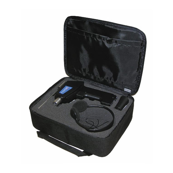
Figure 2. Inspector 400 Kit Contents. Pistol Housing The main component of the Inspector 400 is the pistol housing. Let's define each part. Bargraph Display - The display consists of a ten segment LED bargraph that indicates ultrasonic signal strength. -
Page 21: Scanning Module
(Use a miniphone plug.) Trigger Switch - This is located on the underside of the Inspector 400. The Inspector 400 is always “off” until the trigger switch is pressed. To operate, simply press the trigger; to turn the instrument off, release the trigger. - Page 22 Rubber Focusing Probe - The Rubber Focusing Probe is a circular shaped rubber shield used to block out stray ultrasound, and to assist in narrowing the field of reception of the Scanning Module. It also 1 - 10 Inspector 400 Ultrasonic Probe User Manual...
-
Page 23: Contact (Stethoscope) Module
(such as within a pipe, bearing housing, steam trap or wall). Once stimulated by ultrasound, it transfers the signal to a piezoelectric transducer located directly in the module housing. Figure 3. Scanning Module. Inspector 400 Ultrasonic Probe 1 - 11 User Manual... - Page 24 As with the scanning module, go from the “gross” to the “fine.” Start at sensitivity on the Sensitivity Selection Dial and proceed to reduce the sensitivity until a satisfactory sound and meter level is achieved. 1 - 12 Inspector 400 Ultrasonic Probe User Manual...
-
Page 25: Headset
Headset Headset The headset allows the user to easily hear the sounds received by the Inspector 400. To use, simply plug the headset cord into the headset jack on the pistol housing, and place the headphones over your ears. A... -
Page 27: Inspector 400 Applications
In both instances, the ultrasound is produced in the manner described above. The only difference between the two is that a vacuum leak usually generates less ultrasonic amplitude than a pressure Inspector 400 Ultrasonic Probe 2 - 1 User Manual... - Page 28 Because of its versatility, the Inspector 400 may be utilized in a wide variety of leak detection. Pneumatic systems may be checked, pressurized cables, such as those utilized by telephone companies, may be tested.
- Page 29 In order to focus on the leak, keep reducing the • sensitivity setting and move the instrument closer to the suspected leak site until you are able to confirm a leak. Inspector 400 Ultrasonic Probe 2 - 3 User Manual...
- Page 30 Overcoming Difficulties Competing Ultrasounds If competing ultrasounds make it difficult to isolate a leak, there are two approaches to be taken: 2 - 4 Inspector 400 Ultrasonic Probe User Manual...
- Page 31 Inspector 400 Ultrasonic Probe 2 - 5 User Manual...
- Page 32 Used as an ultra-sonic bubble test, a small amount of LLA is poured over a suspected leak site. It produces a thin film through which the escaping gas passes. When it comes in 2 - 6 Inspector 400 Ultrasonic Probe User Manual...
-
Page 33: Electric Arc, Corona, Tracking Detection
Electric Arc, Corona, Tracking Detection There are three basic electrical problems that are detected with the Inspector 400: Arcing: An arc occurs when electricity flows through space. Lightning is a good example. Corona: When voltage on an electrical... - Page 34 Electric Arc, Corona, Tracking Detection Tracking: Often referred to as “baby arcing,” follows the path of damaged insulation. Although the Inspector 400 can be used in low, medium and high voltage systems, most applications tend to be in medium and high voltage systems.
- Page 35 Once the general area has been located, the scanning module of the Inspector 400 is utilized with a general scan of the area. The sensitivity is reduced if the signal is too strong to follow. When this occurs,...
-
Page 36: General Mechanical Inspection / Detection
(the onset of) bearing failure. The ultrasonic warning generally appears prior to a rise in temperature or an increase in low frequency vibration levels. 2 - 10 Inspector 400 Ultrasonic Probe User Manual... - Page 37 An ultrasonic system based on detection and analysis of modulations of bearing resonance frequencies can provide subtle detection capability similar to the proven SKF method of "Acceleration Enveloping;" whereas conventional vibration monitoring methods are incapable of detecting very slight faults.
- Page 38 “rough” or “scratchy” components indicate a rolling element hitting a “flat” spot and sliding on the bearing surfaces rather than rotating. If this condition is detected, more frequent examinations should be scheduled. 2 - 12 Inspector 400 Ultrasonic Probe User Manual...
-
Page 39: Detecting Bearing Failure
• Compare differences of meter reading and sound quality. It is important to consider two elements of potential failure. One is lack of lubrication, the other is over lubrication. Inspector 400 Ultrasonic Probe 2 - 13 User Manual... - Page 40 Slow Speed Bearings Monitoring slow speed bearings is possible with the Inspector 400. Due to the sensitivity range, it is quite possible to listen to the acoustic quality of bearings. In extremely slow bearings (less than 25 RPM), it is often necessary to disregard the meter and listen to the sound of the bearing.
-
Page 41: General Mechanical Trouble Shooting
Therefore, an ultrasonic history of key components can prevent unplanned down time. And just as important, if equipment should begin to fail in the field, the Inspector 400 can be extremely useful in trouble shooting problems. To trouble shoot: •... -
Page 42: Locating Faulty Steam Traps
• Try to check whether the trap is in operation (is it hot or cold? Put your hand near, but do not touch the trap, or better yet, use an SKF non- contact infrared thermometer). 2 - 16 Inspector 400 Ultrasonic Probe... - Page 43 Check upstream and reduce the sensitivity so that the meter reads about 50% or lower, then touch the trap body downstream and compare readings. Inspector 400 Ultrasonic Probe 2 - 17 User Manual...
- Page 44 This indicates that the vent failed in the open position and is wasting energy. 2 - 18 Inspector 400 Ultrasonic Probe User Manual...
- Page 45 If the trap fails closed, condensate backs up and no sound is heard. If the trap fails open, a continuous rushing of live steam is heard. Inspector 400 Ultrasonic Probe 2 - 19 User Manual...
- Page 46 This is heard as a constant rushing sound. 2 - 20 Inspector 400 Ultrasonic Probe User Manual...
-
Page 47: Locating Faulty Valves
Locating Faulty Valves Figure 12. Utilizing the contact (stethoscope) module in the Inspector 400, valves can be easily monitored to determine if they are operating properly. As a liquid or gas flows through a pipe, there is little or no turbulence generated except at bends or obstacles. - Page 48 (usually bring the meter to a mid-line 50 % reading). • Touch valve seat and/or downstream side. • Compare sonic differentials. If the valve is leaking, the sound level on the seat or 2 - 22 Inspector 400 Ultrasonic Probe User Manual...
- Page 49 If the sound level increases as you approach the • test valve, it is an indication of a leak in the valve. Inspector 400 Ultrasonic Probe 2 - 23 User Manual...
Need help?
Do you have a question about the Inspector 400 and is the answer not in the manual?
Questions and answers