Table of Contents
Advertisement
SKF Multilog On-Line
System IMx-S
User Manual Part No. 32087700-EN
Revision S – November 2019
WARNING! Read this manual before using the product. Failure to follow the
instructions and safety precautions in this manual can result in serious injury, damage to
the product, or incorrect readings. Keep this manual in a safe location for future
reference.
Copyright 2016 by SKF Group
All rights reserved.
SKF Sverige AB
Aurorum 30, 977 75 Luleå, Sweden
Telephone: +46 (0) 31 337 10 00
User manual
Advertisement
Table of Contents

Subscribe to Our Youtube Channel
Related Manuals for SKF Multilog IMx-S Series


Summary of Contents for SKF Multilog IMx-S Series
- Page 1 Keep this manual in a safe location for future reference. Copyright 2016 by SKF Group All rights reserved. SKF Sverige AB Aurorum 30, 977 75 Luleå, Sweden...
- Page 2 SKF reserves the right to alter any part of this publication without prior notice.
-
Page 3: Table Of Contents
Checking Modbus RTU, RS485 communication ..5-8 Technical Data Environmental ............6-1 Power Supply ............6-1 Analogue Inputs ............6-2 Digital Inputs ............6-2 Outputs ..............6-2 SKF Multilog On-Line System IMx-S TOC - 1 User Manual – Revision S... - Page 4 IMx-S 16 Standard Cabinet ........7-1 IMx-S 16 Stainless Steel Cabinet ......7-2 IMx-S 32 Standard & Stainless Steel Cabinet ..7-3 Terminal List ............7-4 Electrical Waste Limited Warranty Index TOC - 2 SKF Multilog On-Line System IMx-S User Manual – Revision S...
-
Page 5: Introduction
IMx-S from mains power. The switch must be labelled "IMx-S” or si ilar with the On/Off position clearly marked. The switch must be located close to the IMx-S, within an operator's easy reach. SKF Multilog On-Line System IMx-S 1 - 1 User Manual – Revision S... -
Page 6: System Overview
Always consult SKF before using the external mains output. System Overview The IMx-S is a part of the SKF Multilog On-line System product range and is designed to be used for a variety of condition monitoring applications. In conjunction with SKF... -
Page 7: Imx-S Unit
It is also possible to connect different types of on-line units in the same network, for example, IMx-S together with other IMx units and/or MasCon systems. IMx-S Unit Figure 1 - 2. SKF Multilog On-line System IMx-S 16 (left) and IMx-S 32 (right). IMx-S 16 • Up to 16 analogue channels. -
Page 8: System Led Indicators
➢ Note that SYS LED is on for a short time when the system is cold booted or re-started. • Green PWR LED indicates the status of power. On means that the power is Ok. 1 - 4 SKF Multilog On-Line System IMx-S User Manual – Revision S... -
Page 9: Installation
Installation errors can lead to a situation where the system does not work as intended and machinery faults go undetected. In case of questions arising during installation contact TSG (Technical Support Group) for advice. ➢ Installation errors that require the involvement of SKF personnel to rectify, may incur additional charges. Safety Considerations Observe all site safety requirements including any that may be specific to the machines or areas where the installation is being carried out. -
Page 10: Supply Cable
GPRS forms a part of the customers internal IP network (VPN). In such a case, SKF must be informed of this before ordering the GPRS, so that SKF can disable the lifeline functionality of the GPRS router. - Page 11 Important - All externally provided equipment must be evaluated individually and approved together with IMx-S unit regarding EMC and safety requirements (CE and ETL). Always consult SKF before using the external mains output. SKF Multilog On-Line System IMx-S 2 - 3...
-
Page 12: Sensor Cables
For lengths up to 15 metres, it is recommended to use pre-fabricated Ethernet twisted pair cable FTP type, CAT5/6. For longer cable lengths, it is recommended to use S-FTP (screened shielded twisted pair) Ethernet cable CAT5/6. 2 - 4 SKF Multilog On-Line System IMx-S User Manual – Revision S... -
Page 13: Ethernet Connections
V-1 or better. All cable glands must also meet or exceed IP65 so as to maintain the IP rating of the enclosure. SKF Multilog On-Line System IMx-S 2 - 5 User Manual – Revision S... -
Page 15: Unit Configuration
Figure 3 - 1. IMx-S Terminal Connection, Standard Accelerometer. The IMx-S I/O board along with the corresponding analogue terminal list are shown below. SKF Multilog On-Line System IMx-S 3 - 1 User Manual – Revision S... - Page 16 (max 35 mA) Signal Com. 4–20 mA (IMx + Signal 100101 – Signal powered) N.C. N.C. = Not Connected DIP switch setting 1 = ON, 0 = OFF 3 - 2 SKF Multilog On-Line System IMx-S User Manual – Revision S...
-
Page 17: Digital Inputs
IMx-S 16 10 W IMx-S 32 10 W (at 60 ˚C [140 °F] only IEPE sensors are recommended) At lower temperatures more total sensor power is allowed; please contact TSG or an SKF application engineer. Important - Do NOT change DIP switch settings while the IMx-S unit is powered, as this may cause damage and void warranty. - Page 18 They are only used for externally powered signals with signal level of 12 to 24 V, square wave signal. Table 3-6: Digital inputs 5 to 8 terminal list. Signal Terminal Pulse 12–24 V – (external power) 3 - 4 SKF Multilog On-Line System IMx-S User Manual – Revision S...
-
Page 19: Rs485 Communication
Modbus master or as a Modbus slave device. For more information regarding RS485/Modbus and the different configurations that are supported, refer to the appropriate user manual, "Modbus for SKF IMx and @ptitude Observer" o Modbus for SKF IMx and @ptitude Analyst a d also the appli atio ote Ge e al Mod us Protocol Considerations for IMx-Devices"... -
Page 20: Relay Driver Outputs
Relay Driver Output Connections. Note that terminals Dig +12V always have the voltage +12 V, whereas terminals Dig1 OUT to Dig4 OUT are low side drivers known as open collectors. 3 - 6 SKF Multilog On-Line System IMx-S User Manual – Revision S... -
Page 21: Dig1 Buffered Output
➢ On I/O board v1.24 and greater, those with a hole in front panel for DIP21, the phase of the buffered output has been inverted. This inverted buffered out will then have the same phase as the input signal. SKF Multilog On-Line System IMx-S 3 - 7 User Manual – Revision S... -
Page 22: Network Configuration
For Observer clients: Online Device Configurator. For detailed information, refer to the @ptitude Observer On-line Device Configurator User Manual. • For Analyst clients: Multilog IMx Configurator in Admin Tools under SKF @ptitude Monitoring Suite. There are two ways to configure a network and ID configuration: •... - Page 23 RS232 connector at any other time. Table 3-11: RS232 connector pinout. RS232 Connector Pinout Description N.C. N.C. N.C. N.C. N.C. N.C. N.C. = Not Connected SKF Multilog On-Line System IMx-S 3 - 9 User Manual – Revision S...
-
Page 24: Imx-S Time
In @ptitude Observer, the function is found under a tab menu called "On-line", then "MasCon/IMx units" interface. In @ptitude Analyst, the function is found at Transfer / Online / Status. 3 - 10 SKF Multilog On-Line System IMx-S User Manual – Revision S... -
Page 25: Hardware Maintenance
Hardware Maintenance The IMx-S hardware, i.e. the IMx-S unit is maintenance free. However, customers are advised to undertake an annual visual inspection of the equipment. SKF Multilog On-Line System IMx-S 4 - 1 User Manual – Revision S... -
Page 27: Troubleshooting Guide
Be aware that invasive troubleshooting may cause changes in alarm or channel status in the IMx-S and any interconnected systems. Whilst striving to provide information that is as accurate as possible, SKF cannot be held responsible for any injury or damage to persons or material that occur in the interpretation of or due to actions taken, based on information in this document. - Page 28 Reconnect the cable on the IMx-S terminal block and again measure the voltage across the two terminals. Does the short circuit remain (voltage close to zero)? 5 - 2 SKF Multilog On-Line System IMx-S User Manual – Revision S...
- Page 29 YES: Check first the configuration settings for this channel, especially the DIP switches. If all appears as expected, the fault may be with the IMx-S device, contact TSG for advice and further information. SKF Multilog On-Line System IMx-S 5 - 3 User Manual – Revision S...
- Page 30 Ensure the correct signal type has been chosen at the DIP switches and that the wiring is appropriately applied, noting particularly the difference between loop and IMx powered, 4-20 mA, circuits. 5 - 4 SKF Multilog On-Line System IMx-S User Manual – Revision S...
- Page 31 2. Disconnect the signal wire from terminal A and recheck the DC voltage between that and the common terminal, B. Is the voltage now as expected, for the connected signal, type? SKF Multilog On-Line System IMx-S 5 - 5 User Manual – Revision S...
- Page 32 0 (common) terminals on an oscilloscope. Is the expected pulsed waveform present? NO: Cable, sensor or installation issue. If practicable replace the sensor by a signal source to test the measurement chain, excluding sensor/target, and to verify 5 - 6 SKF Multilog On-Line System IMx-S User Manual – Revision S...
-
Page 33: Relay Driver Outputs
YES: Check again that the correct relay output is being tested and that the configuration is correct. Check also that this relay is wired to the correct IMx-S, relay driver output. SKF Multilog On-Line System IMx-S 5 - 7 User Manual – Revision S... -
Page 34: Connections To Monitor
Incorrect addressing, such as a mismatch between the address at which the master understands the slave resides and that actual address, will result in unanswered messages. 5 - 8 SKF Multilog On-Line System IMx-S User Manual – Revision S... - Page 35 3.5 characters at the configured baud rate, has elapsed since the end of the command. SKF has identified that some Modbus transducers do not always adhere to these requirements and consequently a reply sent without observing the required 3.5 character gap risks not being recognised as a valid message.
- Page 36 RS485 termination is done correctly This process of checking Modbus communication can be repeated, as required during the installation/test to confirm communications activity or the lack of it. 5 - 10 SKF Multilog On-Line System IMx-S User Manual – Revision S...
-
Page 37: Technical Data
Maximum altitude: 2 000 m (6 561.7 ft.) Power Supply • 100 to 240 VAC, 47 to 63 Hz • Power consumption: – IMx-S 16: 30 W – IMx-S 32: 60 W SKF Multilog On-Line System IMx-S 6 - 1 User Manual – Revision S... -
Page 38: Analogue Inputs
24-bit AD conversion enabling continuous transient capture (no gain or AC/DC switching necessary) • True simultaneous sampling, with no multiplexing: – IMx-S 16: all 16 channels – IMx-S 32: all 32 channels 6 - 2 SKF Multilog On-Line System IMx-S User Manual – Revision S... -
Page 39: Digital Measurement
Data storage on time, event or alarm condition • Data buffering in flash memory when communication link is down • Detection of sensor and cable fault • Watchdog and self-testing SKF Multilog On-Line System IMx-S 6 - 3 User Manual – Revision S... -
Page 40: Interface
• Calibration, traceable to BIPM • CE certified according to EN61000-6-3 and EN61000-6-2 • Support IEC 61850 Quality Control SKF Sverige AB, Luleå is ISO 9001:2015 certified. 6 - 4 SKF Multilog On-Line System IMx-S User Manual – Revision S... -
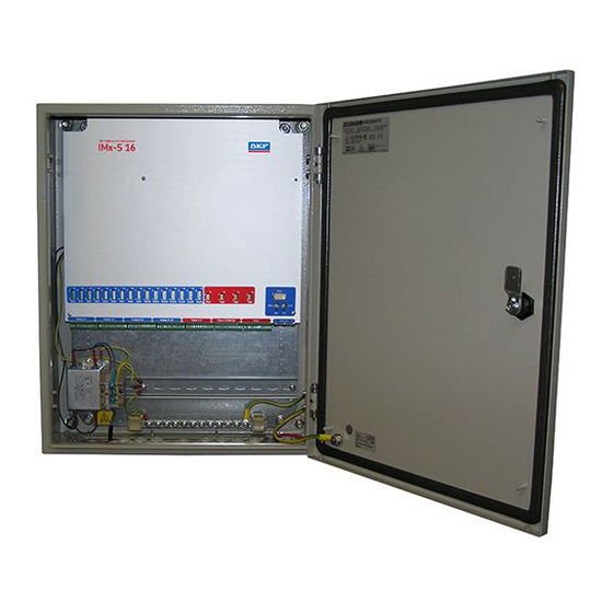
Page 41: Imx-S Drawings
IMx-S Drawings IMx-S 16 Standard Cabinet Figure 7 - 1. IMx-S 16 Standard Cabinet. SKF Multilog On-Line System IMx-S 7 - 1 User Manual – Revision S... -
Page 42: Imx-S 16 Stainless Steel Cabinet
IMx-S Drawings IMx-S 16 Stainless Steel Cabinet IMx-S 16 Stainless Steel Cabinet Figure 7 - 2. IMx-S 16 Stainless Steel Cabinet. 7 - 2 SKF Multilog On-Line System IMx-S User Manual – Revision S... -
Page 43: Imx-S 32 Standard & Stainless Steel Cabinet
IMx-S Drawings IMx-S 32 Standard & Stainless Steel Cabinet IMx-S 32 Standard & Stainless Steel Cabinet Figure 7 - 3. IMx-S 32 Standard & Stainless Steel Cabinet. SKF Multilog On-Line System IMx-S 7 - 3 User Manual – Revision S... -
Page 44: Terminal List
IMx-S Drawings Terminal List Terminal List Table 8-1: Terminal list. 1 to 48 49 to 84 7 - 4 SKF Multilog On-Line System IMx-S User Manual – Revision S... -
Page 45: Electrical Waste
Electrical waste and electrical equipment should be recycled according to the WEEE- directive and not be placed in the general refuse. Product should be sent to an approved recycling centre for safe recycling, recovery, reuse or sent to SKF Sverige AB for proper recycling. - Page 47 Shaft Alignment Systems TKSA 60 and provided, however, that SKF shall not be liable TKSA 80 including hand-held computer, for any claim for which notice is received by SKF measuring units and accessories. more than thirty (30) days following the...
- Page 48 SKF-supplied or SKF-approved devices terms of this Limited Lifetime Warranty and/or components. The computer provided by during the life of such products, SKF, in its Buyer must meet the requirements stipulated by sole discretion, will repair, replace or SKF.
- Page 49 “KF s sole o ligatio s u de this Li ited writing by SKF, Buyer shall forward to SKF any Lifetime Warranty are set forth in Product claimed by Buyer as being defective.
- Page 50 IMPLIED, INCLUDING WITHOUT warranty shall not be deemed to have failed of LIMITATION ANY IMPLIED WARRANTY their essential purpose so long as SKF is willing OF MERCHANTABILITY, FITNESS FOR A and able to perform to the extent and in the PARTICULAR PURPOSE, OR NON- manner prescribed in this limited warranty.
- Page 51 3-8 fire enclosure requirements 2-1 null modem cable 3-10 frequency range 6-2, 6-3 fuse holder 2-3 ODBC 1-2 On-line Device Configurator 3-8 GPRS router 2-2 outputs 6-2 SKF Multilog On-Line System IMx-S Index - 1 User Manual – Revision S...
- Page 52 5-1 set time 3-11 signal processing 6-3 signal to noise ratio 6-3 simultaneous sampling 6-2 SKF @ptitude Analyst IMx Service 1-2 SKF @ptitude Observer Monitor Service 1-2 SKF Multilog On-line System 1-2 software controlled relay outputs 3-6 special care 1-1...
Need help?
Do you have a question about the Multilog IMx-S Series and is the answer not in the manual?
Questions and answers