Table of Contents
Advertisement
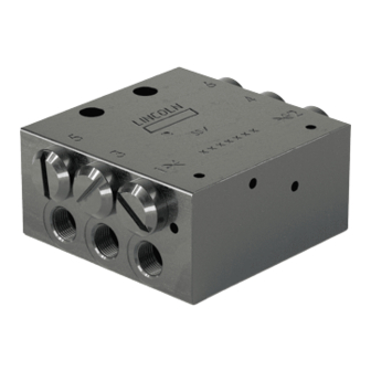
Progressive metering devices of the
SSV, SSV-E, SSVM, SSVD, SSVD-E, SSVL
and SSVDL series
5
6
5
LINCOLN
3
4
3
An SKF Group Brand
SSV
1
2
1
XXXXXXX
MADE IN XXXXXXX
951-171-049-EN
Version 02
22/05/2019
5
LINCOLN
6
3
An SKF Group Brand
LINCOLN
4
SSVL
An SKF Group Brand
SSV-E
1
2
XXXXXXX
XXXXXXX
MADE IN XXXXXXX
MADE IN XXXXXXX
Assembly Instructions
6
4
2
EN
Advertisement
Table of Contents

Related Manuals for SKF SSV Series


Summary of Contents for SKF SSV Series
- Page 1 Assembly Instructions Progressive metering devices of the SSV, SSV-E, SSVM, SSVD, SSVD-E, SSVL and SSVDL series LINCOLN An SKF Group Brand LINCOLN LINCOLN SSVL An SKF Group Brand An SKF Group Brand SSV-E XXXXXXX XXXXXXX XXXXXXX MADE IN XXXXXXX MADE IN XXXXXXX...
-
Page 2: Legal Notice
○ Intent or negligence Warranty Berlin Facilities The instructions do not contain any informa- ○ Use of non-original SKF spare parts Motzener Straße 35/37 tion on the warranty. This can be found in ○ Faulty planning or layout of the central- 12277 Berlin our general terms and conditions. -
Page 3: Table Of Contents
Table of contents Table of contents Legal notice ....................2 Explanation of symbols, signs and abbreviations ........6 Safety instructions .................8 Temperature characteristics ..............17 General safety instructions ..............8 Ageing of lubricants ................17 General behaviour when handling the product ........8 Solid lubricants in lubrication greases ..........18 Intended use .................... - Page 4 Table of contents Technical data proximity switch DC version ........46 Optional mounting bracket for SSV, SSV-E, SSVD and SSVD-E ..58 Technical data proximity switch AC/DC version .........47 Venting of the SSV metering devices and the progressive Technical data proximity switch DC version for SSVM ......48 lubrication system.................58 Technical data limit switch ..............49 Initial start-up ................
- Page 5 Table of contents Spare parts ................. 66 14.1 SSV Metering devices ................66 14.2 SSV-E metering devices ..............68 14.3 SSVD metering devices ................69 14.4 SSVL metering devices .................71 14.5 SSVDL metering devices ..............71 14.6 SSVM metering devices ...............72 14.7 SSVD-E metering devices ..............72 14.8 Metering screws for SSVD, SSVD-E ...........72 14.9...
-
Page 6: Explanation Of Symbols, Signs And Abbreviations
Explanation of symbols, signs and abbreviations Explanation of symbols, signs and abbreviations The following abbreviations may be used within these instructions. Symbols within safety notes mark the kind and source of the hazard. General warning Dangerous electrical voltage Risk of falling Hot surfaces Unintentional intake Crushing hazard... - Page 7 Explanation of symbols, signs and abbreviations Fig. 1 Abbreviations and conversion factors regarding °C degrees Celsius °F degrees Fahrenheit approx. approximately Kelvin ounce i.e. that is Newton fl. oz. fluid ounce poss. possibly hour inch if appl. if applicable second pounds per square inch incl.
-
Page 8: Safety Instructions
1. Safety instructions 1. Safety instructions 1.2 General behaviour when handling 1.1 General safety instructions ○ Responsibilities for different activities the product ○ The owner must ensure that safety infor- must be clearly defined and observed. ○ The product may be used only in aware- Uncertainty seriously endangers safety. -
Page 9: Intended Use
1. Safety instructions 1.3 Intended use ○ to supply, transport, or store hazardous Providing lubrication points with lubricant in progressive lubrication systems following substances and mixtures in accordance the specifications, technical data and limits with annex I part 2-5 of the CLP regula- stated in these Instructions. -
Page 10: Reference On Pressure Equipment Directive 2014/68/Eu
1. Safety instructions 1.5 Reference on Pressure Equipment 1.8 Other applicable documents Directive 2014/68/EU In addition to these instructions, the fol- Because of its performance data the product lowing documents must be observed by the does not achieve the limit values defined in respective target group: Article 4 (1) (a) (ii) and is therefore excluded ○... -
Page 11: Persons Authorized To Operate The Pump
1. Safety instructions 1.10 Brieing of external technicians 1.9 Persons authorized to operate the 1.12 Operation pump Prior to commencing the activities, external The following must be observed during technicians must be informed by the opera- commissioning and operation. tor of the company safety provisions, the 1.9.1 Operator ○... -
Page 12: Transport, Installation, Maintenance, Malfunctions, Repair, Shutdown, Disposal
1. Safety instructions ○ Ensure through suitable measures that ○ Undertake drilling at non-critical, non- 1.14 Transport, installation, maintenance, malfunctions, repair, shutdown, movable or detached parts are immobi- load bearing parts only. Use any available disposal lized during the work and that no limbs boreholes. -
Page 13: Initial Commissioning / Daily Start-Up
1. Safety instructions ○ All components used must be designed 1.15 Initial commissioning / daily start-up 1.16 Cleaning according to the maximum operating ○ Risk of fire and explosion when using Ensure that: pressure and the maximum respectively inflammable cleaning agents Only use ○... -
Page 14: Markings And Conventions
= chemically nickel-plated no indication = black galvanized Conventions = Outlet level Metering-piston level (in case of LINCOLN doseable metering devices) = Control-piston level An SKF Group Brand SSVxxx = Inlet level XXXXXXX MADE IN XXXXXXX 951-171-049 - 14 - Version 02... -
Page 15: Residual Risks
1. Safety instructions 1.18 Residual risks Residual risk Possible in life cycle Prevention/ remedy Personal injury/ material damage due to fall- Keep unauthorized persons away. No people may remain under suspended A B C G H K ing of raised parts loads. -
Page 16: Lubricants
This may have unforeseeable order to avoid this, always use ○ Noise minimisation effects on the usability and lubricants tested by SKF. therefore on the function of the ○ protection against contamination or centralized lubrication system. penetration of foreign objects ○... -
Page 17: Selection Of Lubricants
(e.g. "bleeding"). feeding the selected lubricant and to plan and design their centralized lubrication Please contact SKF. if you have further ques- system. tions regarding lubricants. You will avoid possible downtimes due to a damage to your machine or damage to the centralized lubrication system. -
Page 18: Solid Lubricants In Lubrication Greases
2. Lubricants 2.6 Solid lubricants in lubrication greases 2.6.1 Chisel pastes Calcium hydroxide With regard to the different solid lubricants, Lubricants containing calcium hydroxide are NOTICE please observe the following: likely to harden strongly, what may result in a downtime of the centralized lubrication Graphite Damage to the superior machine system... -
Page 19: Overview, Functional Description
LINCOLN An SKF Group Brand SSVxxx XXXXXXX MADE IN XXXXXXX 951-171-049 Version 02... -
Page 20: Fields Of Application
3. Overview, functional description 3.2 Fields of application SSV metering devices can be used for almost Fig. 4 Example of a progressive lubrication system with SSV metering devices all types of applications within a progressive lubrication system. Typical fields of application: ○... -
Page 21: Function Monitoring Options
3. Overview, functional description 3.3 Function monitoring options 3.3.3 Electrical monitoring/controlling via piston detector The described metering devices offer the following function monitoring respectively The piston detector detects the movement controlling options. Which of the specified of the metering piston. Piston detectors are function monitoring options are possible for used in combination with lubrication pumps the respective metering device models can... - Page 22 PCB or by an external control unit. An SKF Group Brand The respective designation depends on the XXXXXXX type of connection of the piston detector (see MADE IN XXXXXXX...
-
Page 23: Course Of The Lubricant In The Ssv Metering Device
3. Overview, functional description 3.4 Course of the lubricant in the SSV metering device Fig. 6 Lubricant supply sequence illustrated by means of an SSV-8 metering device phase 1 The SSV 8 metering device is used as an example to show the order of the lubricant output to the individual outlets. - Page 24 3. Overview, functional description Fig. 7 Course of the lubricant illustrated by means of an SSV-8 metering device Stage 2 Phase 2 When piston A reaches its left end position, it opens the connection duct to the right end of piston B. As a consequence lubricant P1 supplied by the pump flows to the right end of piston B and piston B moves to its left end position.
- Page 25 3. Overview, functional description Fig. 8 Course of the lubricant illustrated by means of an SSV-8 metering device phase 3 Phase 3 When piston B reaches its left end position, it opens the connection duct to the right end of piston C. As a consequence lubricant P1 supplied by the pump flows to the right end of piston C and piston C moves to its left end position.
- Page 26 3. Overview, functional description Fig. 9 Course of the lubricant illustrated by means of an SSV-8 metering device phase 4 Phase 4 When piston C reaches its left end position, it opens the connection duct to the right end of piston D. As a consequence lubricant P1 supplied by the pump flows to the right end of piston D and piston D moves to its left end position.
- Page 27 3. Overview, functional description Fig. 10 Course of the lubricant in the metering device phase 5 Phase 5 When piston D reaches its left end position, it opens the connection duct to the right end of piston A. As a consequence lubricant P1 supplied by the pump flows to the right end of piston A and piston A moves to its left end position.
-
Page 28: Course Of The Lubricant In The Ssvd Metering Device
4. Technical data 3.5 Course of the lubricant in the SSVD metering device Fig. 11 Course of the lubricant illustrated by means of an SSVD-6 metering device phase 1 The SSVD 6 metering device is used as an example to show the piston movements and the lubricant supply to the individual outlets. - Page 29 4. Technical data Fig. 12 Course of the lubricant illustrated by means of an SSVD-6 metering device Stage 2 Phase 2 As soon as metering piston B1 reaches its left end position, the pressurized lubricant P2 moves the control piston B2 leftward and additionally displaces the lubricant in front of control piston B2 to outlet 6.
- Page 30 4. Technical data Fig. 13 Course of the lubricant illustrated by means of an SSVD-6 metering device phases 3 and 4 Phase 3 The control piston B2 has reached its left end position. Thereby it opens the connec- tion duct to the right end of control piston C2 and metering piston C1.
- Page 31 4. Technical data Phase 5 Fig. 14 Course of the lubricant illustrated by means of an SSVD-6 metering device phases 5 and 6 The control piston C2 has reached its left end position. Thereby it opens the connec- tion duct to the left end of control piston A2 and metering piston A1.
- Page 32 4. Technical data Fig. 15 Course of the lubricant illustrated by means of an SSVD-6 metering device phases 7 and 8 Phase 7 Control piston A2 has reached its right end position. Thereby it opens the connection duct to the left end of control piston B2 and metering piston B1.
- Page 33 4. Technical data Fig. 16 Course of the lubricant illustrated by means of an SSVD-6 metering device phases 9 and 10 Phase 9 The control piston B2 has reached its right end position. Thereby it opens the connec- tion duct to the left end of control piston C2 and metering piston C1.
- Page 34 4. Technical data Fig. 17 Course of the lubricant illustrated by means of an Phase 11 SSVD-6 metering device phases 11 and 12 The control piston C2 has reached its right end position. Thereby it opens the connec- tion duct to the right end of control piston A2 and metering piston A1.
-
Page 35: Technical Data
4. Technical data 4. Technical data 4.1 Technical data SSV/SSV-E/SSVM SSV-E SSVM LINCOLN LINCOLN An SKF Group Brand LINCOLN An SKF Group Brand An SKF Group Brand SSVM SSV-E XXXXXXX XXXXXXX XXXXXXX MADE IN XXXXXXX MADE IN XXXXXXX MADE IN XXXXXXX... -
Page 36: Construction Sizes, Dimensions And Weights Ssv/Ssv-E/Ssvm
30/45* 30/45* SSVM Weight Height Width Depth Outlets (kg) (mm) (mm) (mm) An SKF Group Brand 48.5 An SKF Group Brand XXXXXXX XXXXXXX MADE IN XXXXXXX MADE IN XXXXXXX 71.5 * SSV-E: Depth including emergency lubri- cation fitting G1/8 G1/8... -
Page 37: Tightening Torques Ssv/Ssv-E
10 ± 1.0 M 6 x ..(8.8) oiled 7.5 ± 0.8 An SKF Group Brand XXXXXXX MADE IN XXXXXXX Secure all lubrication fittings and all screw fittings without sealing edges with a medium-strength screw lock (e.g. Loctite 274). *In case of an oiled assembly reduce the stated tightening torques by 20%. -
Page 38: Tightening Torques Ssvm
6 ± 0.6 M 5 x ..(8.8) oiled 4.5 ± 0.4 An SKF Group Brand XXXXXXX E1 / E2 MADE IN XXXXXXX Secure all lubrication fittings and all screw fittings without sealing edges with a medium-strength screw lock (e.g. Loctite 274). -
Page 39: Technical Data Ssvd/Ssvd-E
4. Technical data 4.2 Technical data SSVD/SSVD-E SSVD SSVD-E LINCOLN LINCOLN An SKF Group Brand An SKF Group Brand XXXXXXX XXXXXXX MADE IN XXXXXXX MADE IN XXXXXXX Maximum operating pressure Minimum operating pressure Max. differential pressure between 2 outlets Number of outlets... -
Page 40: Construction Sizes, Dimensions And Weights Ssvd/Ssvd-E
Width Depth SSVD/SSVD-E (kg) Outlets (mm) (mm) (mm) 40/55* 40/55* 40/55* 40/55* 40/55* 40/55* 40/55* 40/55* 40/55* * SSVD-E: Depth including emergency lubrica- tion fitting An SKF Group Brand XXXXXXX MADE IN XXXXXXX G1/8 951-171-049 - 40 - Version 02... -
Page 41: Tightening Torques Ssvd/Ssvd-E
Metering screws (SSVD) 15 ± 1.0 Fastening screws M 6 x ..(8.8) dry 10 ± 1.0 An SKF Group Brand M 6 x ..(8.8) oiled 7.5 ± 0.8 XXXXXXX MADE IN XXXXXXX Secure all lubrication fittings and all screw fittings without sealing edges with a medium-strength screw lock (e.g. Loctite 274). -
Page 42: Technical Data Of The Ssvl/Ssvdl
4. Technical data 4.3 Technical data of the SSVL/SSVDL SSVL SSVDL LINCOLN An SKF Group Brand LINCOLN An SKF Group Brand XXXXXXX XXXXXXX MADE IN XXXXXXX MADE IN XXXXXXX Maximum operating pressure Minimum operating pressure Max. differential pressure between 2 outlets... -
Page 43: Ssvl/Ssvdl
Height Width Depth Outlets (kg) 4 x 6,6 (mm) (mm) (mm) An SKF Group Brand An SKF Group Brand XXXXXXX XXXXXXX MADE IN XXXXXXX MADE IN XXXXXXX 23,4 When using a metering device with monito- G1/4 ring, additional free space may be required. -
Page 44: Tightening Torques Ssvl, Ssvdl
35 + 3.0 (Ø 8 mm) E4/G4 for steel tube Ø 10 x 2 mm 40 + 4.0 15 + 2.0 An SKF Group Brand Metering screws (SSVDL only) (Ø 10 mm) XXXXXXX 15 ± 1.5 MADE IN XXXXXXX C3 / C4 Fastening screws M 6 x .. -
Page 45: Technical Data Of The Universal Piston Detector
4. Technical data 4.5 Technical data of the universal piston detector Part number 234-13163-9 Dimensional drawing Ambient temperature [°C] -40 ..+85 Materials Sensor surface: 1.4404; housing = 1.4016, plug = PEI Type of installation Flush mounted in the adapter Switching status display yellow (lit during damping) Electrical connection M12x1 connector, gold-plated contacts... -
Page 46: Technical Data Proximity Switch Dc Version
4. Technical data 4.6 Technical data proximity switch DC version Part number 234-10812-8 Dimensional drawing Ambient temperature [°C] -25 ..+70 Materials Housing = Nickel-plated brass, active area = PBT Type of installation flush Type of connection | Cable diameter [mm] 2000 mm PVC cable | 3.2 mm Cable version| Core cross-section PBT | 3 x 0.14... -
Page 47: Technical Data Proximity Switch Ac/Dc Version
4. Technical data 4.7 Technical data proximity switch AC/DC version Part number 234-13180-3 Dimensional drawing Ambient temperature [°C] -25 ..+80 Materials Materials = nickel-plated brass Type of installation flush Type of connection [mm] 2000 mm PUR cable Core cross-section 2 x 0.25 Switching status display yellow (lit during damping) Rated operating distance... -
Page 48: Technical Data Proximity Switch Dc Version For Ssvm
4. Technical data 4.8 Technical data proximity switch DC version for SSVM Part number 234-10757-4 Dimensional drawing Ambient temperature [°C] -25 ..+70 Materials Housing = Stainless steel, active area = POM Type of installation flush Switching status display yellow (lit during damping) Electrical connection Plug-in connector, 3-wire Rated voltage... -
Page 49: Technical Data Limit Switch
4. Technical data 4.9 Technical data limit switch Part number 236-13281-2 Dimensional drawing Ambient temperature [°C] -40 ..+85 Materials Nylon, fibre glass reinforced 10,5 Ø 2,4 Ø 3,2 Type of actuator Stainless steel plunger sealed with elastomer bellows Rated contact current 5A at 250 AC Contact arrangement NO contact SP/ NC contact... -
Page 50: Delivery, Returns, And Storage
5.3 Storage 5.4 Storage temperature range ○ In case of parts not filled with lubricant After receipt of the shipment, check the SKF products are subject to the following shipment for damage and completeness storage conditions: the admissible storage temperature according to the shipping documents. -
Page 51: Storage Conditions For Parts Filled With Lubricant
5. Delivery, returns, and storage 5.5 Storage conditions for parts illed 5.5.3 Storage period exceeding 18 with lubricant months To avoid dysfunctions consult the manufac- The conditions mentioned in the follow- Metering device turer before commissioning. The general ing will have to be adhered to when storing •... -
Page 52: Installation
6. Installation 6. Installation 6.3 Prerequisites for the correct functio- 6.1 Prior to installation ning of the metering devices Prior to installation observe the following ○ Use adequate lubricant without contami- The following points must be observed dur- points: nations only ing installation to ensure correct functioning ○... -
Page 53: Changing The Metering Volume Internally
Further increasing of the output per outlet is possible only by an external combining, e.g. LINCOLN NOTICE by means of a T-piece or by using metering An SKF Group Brand devices with bypass bores. Damage to the superior machine - For metering devices with indicator pin XXXXXXX... -
Page 54: Metering Devices With Bypass Bores
1 and Outlets 1 and 2 drilled with each other, outlet An SKF Group Brand 2 are internally cross-ported (drilled with 2 closed: each other). By doing so and different from è... -
Page 55: Ssvd, Ssvd-E And Ssvdl Metering Devices
6. Installation 6.4.3 SSVD, SSVD-E and SSVDL Fig. 21 Metering screws metering devices The output of the SSV, SSVD-E and SSVDL metering devices can be adapted by using different metering screws. An additional adaptation is possible by closing unneeded 1.80 1.40 1.00 0.80... -
Page 56: External Combination Of The Output In Case Of Ssvl And Ssvdl
6. Installation 6.5 External combination of the output in Fig. 22 SSVL metering devices with double and triple output case of SSVL and SSVDL NOTICE Risk of damage to the superior machine due to poor supply In case of SSVDL metering devices the outlets must not be closed directly at the metering device housing. -
Page 57: Fixation Of The Metering Device At The Place Of Installation
Position the metering device to be mounted at the place of installation. Transfer the drill LINCOLN pattern and then make the corresponding bores. An SKF Group Brand LINCOLN Tightening torques, see corresponding table in these instructions An SKF Group Brand... -
Page 58: Optional Mounting Bracket For Ssv, Ssv-E, Ssvd And Ssvd-E
6. Installation 6.8 Venting of the SSV metering devices 6.7 Optional mounting bracket for SSV, and the progressive lubrication SSV-E, SSVD and SSVD-E Fig. 24 Additional fixation points system For metering device models SSV, SSV-E • First of all configure the main metering SSVD and SSVD-E as of construction size device completely 14 there exists the possibility to addition-... -
Page 59: Initial Start-Up
7. Initial start-up / 8. Operation 7. Initial start-up 8. Operation The start-up is effected in the frame of the SKF products operate automatically to the initial start-up of the fully and correctly greatest possible extent. Basically, activities mounted progressive lubrication system. -
Page 60: Cleaning
• Thorough cleaning of all outer surfaces uct will be required. Thoroughly remove residues of with a damp cloth To do so, contact the SKF Customer Service. cleaning agents from the product and rinse off with clear water. 951-171-049 - 60 -... -
Page 61: Maintenance
10. Maintenance Maintenance Regular and appropriate maintenance is a prerequisite to detect and clear faults in time. The specific timelines have to be determined, verified at regular intervals and adapted, if necessary, by the operator based on the operating conditions. If needed, copy the table for regular mainte- nance activities. -
Page 62: Troubleshooting
11. Troubleshooting Troubleshooting Fig. 26 Fault table 1 In addition to the indications regarding troubleshooting stated here, observe all indications regarding troubleshooting stated in the lubrication pump instructions. To check the individual outlets you may have to run the lubrication pump for a longer period of time as the single outlets are provided with lubricant one after the other and thus there may be required several cycles of the upstream metering device. - Page 63 11. Troubleshooting Fig. 27 Fault table 2 Fault Possible cause Remedy ○ Loosen the lubrication line to the main metering device. If after loosen- ○ Poor lubrication of all lubrication ○ Blockade upstream of the main ing the lubrication line there is no lubricant output from the line, then points metering device the problem is located either in the lubrication line to the main meter-...
-
Page 64: Repair
12. Repairs Repair 12.1 Remedying a blockade ○ When used with piston detector/proximity switch/limit switch fault indication/fault OTICE message on the pump with control unit or Damage to the machine on the external control unit Make sure to eliminate any blockades. To remedy a blockade proceed as described Until elimination switch off the machine in chapter Troubleshooting. -
Page 65: Shutdown And Disposal
13. Shutdown and disposal Shutdown and disposal 13.1 Temporary shutdown The specific classification of the Temporarily shut the system down by: waste is in the waste producer's ○ Switching off the superior machine responsibility, as the European Waste Catalogue provides differ- 13.2 Final shutdown and disassembly ent waste disposal codes for the same type of waste but of differ-... -
Page 66: Spare Parts
14. Spare parts Spare parts 14.1 SSV Metering devices Standard version, black galvanized Standard version, stainless steel 1.4305 (V2A) Standard version, stainless steel 1.4571 (V4A) Designation Part number Designation Part number Designation Part number SSV 6 619-26473-1 SSV 6 (VA 1.4305) 619-27471-1 SSV 6 (VA 1.4571) 619-27824-1... - Page 67 14. Spare parts with indicator, proximity switch (PNP) with with indicator, proximity switch (NPN) with with indicator pin, limit switch and 1 m cable 3 m cable and ferrules 3 m cable and ferrules Designation Qty. Part number Designation Qty. Part number Designation Qty.
-
Page 68: Ssv-E Metering Devices
14. Spare parts 14.2 SSV-E metering devices Standard version, black galvanized Standard version, stainless steel 1.4305 (V2A) with indicator pin, black galvanized Designation Qty. Part number Designation Qty. Part number Designation Qty. Part number SSV 6-E 619-77345-1 SSV 6-E (VA 1.4305) 619-77680-1 SSV 6-E-K 619-77354-1... -
Page 69: Ssvd Metering Devices
14. Spare parts 14.3 SSVD metering devices Standard version, black galvanized with indicator pin, black galvanized With indicator pin and bypass bore, black galvanized Designation Qty. Part number Designation Qty. Part number Designation Qty. Part number SSVD 6 649-29485-1 SSVD 6 -..-...-K 649-29505-1 SSVD 6/5 -V1-...-K 649-29510-1... - Page 70 14. Spare parts With piston detector and bayonet plug with 3 m With piston detector, 3 m cable and ferrules, black With piston detector, 3 m cable with ferrules and cable, black galvanized galvanized bypass bore, black galvanized Designation Qty. Part number Designation Qty.
-
Page 71: Ssvl Metering Devices
14. Spare parts 14.4 SSVL metering devices Standard version, black galvanized with indicator pin, black galvanized with bypass bore, black galvanized Designation Qty. Part number Designation Qty. Part number Designation Qty. Part number SSVL 6 619-77162-1 SSVL 6-K 619-77231-1 SSVL 6/5-V1 619-77311-1 SSVL 8 619-77163-1... -
Page 72: Ssvm Metering Devices
14. Spare parts 14.6 SSVM metering devices 14.8 Metering screws for SSVD, SSVD-E Standard version, black galvanized Length Metered volume Coding Qty. Part number Designation Qty. Part number [mm] /stroke] SSVM 6 619-26761-1 46.7 0.08 549-34254-1 SSVM 8 619-37044-1 14/B 45.9 0.14 549-34254-2... -
Page 73: Outlet Cap Screws
14. Spare parts 14.9 Outlet cap screws Designation Qty. Part number Outlet cap screw with sealing edge for SSV, SSV-E, SSVD, SSVD-E 303-17499-3 Outlet cap screw with sealing edge for SSVM 303-16284-1 14.10 Mounting bracket SSV Designation Qty. Part number Mounting bracket SSV and SSV-E as of size 14 519-34271-1 Mounting brackets SSVD and SSVD-E as of size 12... -
Page 74: Universal Piston Detector
14. Spare parts 14.13 Universal piston detector Designation Qty. Part number Universal piston detector with adapter and O-ring 519-85224-1 Universal piston detector with adapter and O-ring and 3 m cable (2-core) 664-85282-7 Universal piston detector with adapter and O-ring and 5 m cable (2-core) 664-85282-8 Universal piston detector with adapter and O-ring and 7 m cable with bayo- 664-85242-5... -
Page 75: Outlet Fittings For Ssvl And Ssvdl
14. Spare parts 14.15 Outlet ittings for SSVL and SSVDL Designation Qty. Part number Outlet fitting GERV 8 L G1/4A (tube Ø 8 mm) 223-13052-2 Outlet fitting GERV10 L G1/4A (tube Ø 10 mm) 223-13052-3 Outlet fitting GERV12 L G1/4A (tube Ø 12 mm) 223-13052-5 14.16 Outlet ittings for SSVL and SSVDL with check valve for connection bar Designation... -
Page 76: Cap Screw G1/4 For Ssvl And Ssvdl
14. Spare parts 14.18 Cap screw G1/4 for SSVL and SSVDL Designation Qty. Part number Cap screw G1/4 for cross-porting of outlets of SSVL and SSVDL 303-16470-1 14.19 Sealing ring Designation Qty. Part number USIT sealing ring for cross-porting of outlets of SSVL and SSVDL 220-12238-9 951-171-049 - 76 -... - Page 77 Notes...
- Page 78 SKF Lubrication Systems Germany GmbH Walldorf Facilities Heinrich-Hertz-Straße 2-8 D - 69190 Walldorf Tel:+49 (0) 6227 33-0 Fax: +49 (0) 6227 33-259 e-mail: Lubrication-germany@skf.com www.skf.com/lubrication 951-171-049-EN Version 2 22/05/2019...
Need help?
Do you have a question about the SSV Series and is the answer not in the manual?
Questions and answers