Siemens SITRANS F series Operating Instructions Manual
Ultrasonic flowmeters
Hide thumbs
Also See for SITRANS F series:
- Operating instructions manual (356 pages) ,
- Quick start manual (220 pages) ,
- Manual (188 pages)
Table of Contents
Advertisement
Quick Links
Download this manual
See also:
Function Manual
Advertisement
Table of Contents

Related Manuals for Siemens SITRANS F series


Summary of Contents for Siemens SITRANS F series
- Page 1 SITRANS F Ultrasonic Flowmeters FST030 (Modbus) Operating Instructions Edition 08/2017 Answers for industry.
- Page 3 Operating Instructions Operating Service and maintenance Diagnosing and troubleshooting Technical data Dimension drawings Modbus communication Certificates and support SIMATIC PDM These Operating Instructions a33pply to Siemens SITRANS FST030 transmitters for use in flowmeter systems with order codes commencing 7ME372 08/2017 A5E37367739-AC...
- Page 4 Note the following: WARNING Siemens products may only be used for the applications described in the catalog and in the relevant technical documentation. If products and components from other manufacturers are used, these must be recommended or approved by Siemens. Proper transport, storage, installation, assembly, commissioning, operation and maintenance are required to ensure that the products operate safely and without any problems.
-
Page 5: Table Of Contents
Table of contents Introduction ............................. 9 Purpose of this documentation ....................9 Product compatibility ......................... 9 Document history ........................10 Device documentation package ....................11 Items supplied ......................... 11 Checking the consignment ..................... 12 Security information ........................ 12 Transportation and storage ..................... 13 Notes on warranty ........................ - Page 6 Table of contents Connecting ............................31 Basic safety notes ........................31 5.1.1 Missing PE/ground connection ....................31 5.1.2 Unsuitable cables, cable glands and/or plugs ............... 32 5.1.3 Lack of equipotential bonding ....................32 5.1.4 Unprotected cable ends ......................32 5.1.5 Improper laying of shielded cables ..................
- Page 7 Table of contents Operating the FST030 ......................72 7.2.1 Fixed display texts ........................72 7.2.2 Reading the process values ....................74 7.2.3 Operating the totalizers ......................76 7.2.4 Handling alarms ........................77 7.2.5 Reading the diagnostic values ....................79 Reading / changing parameters ....................79 7.3.1 Alphanumeric parameters .......................
- Page 8 Table of contents Modbus addressing model ....................125 Modbus communication ....................... 125 Coil configuration ......................... 127 Modbus register mapping ....................128 Integer byte order ......................... 130 Float byte order ........................130 Modbus function codes ......................131 Access control ........................132 Modbus holding registers tables ..................
- Page 9 Table of contents A.9.11.3 FW update change log ......................335 A.9.12 Device reset .......................... 335 A.9.13 Oil table settings ........................336 A.9.14 Communication ........................338 A.9.14.1 Service channel ........................338 A.9.15 Security ..........................338 A.9.15.1 Access management ......................338 Certificates and support ........................341 Certificates ..........................
- Page 10 Table of contents SITRANS F Ultrasonic flowmeters FST030 (Modbus) Operating Instructions, 08/2017, A5E37367739-AC...
-
Page 11: Introduction
In order to operate an ultrasonic flow meter, you need both the transmitter Operating Instructions and the sensor Installation Manual, see Flow documentation (https://support.industry.siemens.com/cs/products?pnid=17317&lc=en-WW). Purpose of this documentation These instructions contain all information required to commission and use the device. Read the instructions carefully prior to installation and commissioning. -
Page 12: Document History
Edition Note 08/2017 Chapter: Safety notes. Use in hazardous areas. Special conditions for safe use. Added: Must be installed • in accordance with Siemens control drawing A5E32778336A. 02/2017 First edition • SITRANS F Ultrasonic flowmeters FST030 (Modbus) Operating Instructions, 08/2017, A5E37367739-AC... -
Page 13: Device Documentation Package
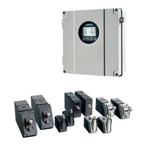
Wall mount enclosure With internal DSL (Digital Sensor Link) • SITRANS FST030 wall mount enclosure transmitter with internal DSL • Siemens Process Instrumentation documentation disk containing certificates, and manuals for ATEX approved devices SITRANS F Ultrasonic flowmeters FST030 (Modbus) Operating Instructions, 08/2017, A5E37367739-AC... -
Page 14: Checking The Consignment
Note The SD-Card Mass Storage functionality has been disabled by SIEMENS on all products sold or imported in the United States. Products having enabled SD-Card Mass storage functionality are intended to be used solely outside the United States and should not be imported into the United States by the user. -
Page 15: Transportation And Storage
In order to protect plants, systems, machines and networks against cyber threats, it is necessary to implement – and continuously maintain – a holistic, state-of-the-art industrial security concept. Siemens’ products and solutions only form one element of such a concept. Customer is responsible to prevent unauthorized access to its plants, systems, machines and networks. -
Page 16: Notes On Warranty
The sales contract contains all obligations on the part of Siemens as well as the complete and solely applicable warranty conditions. Any statements regarding device versions described in the manual do not create new warranties or modify the existing warranty. -
Page 17: Safety Notes
Safety notes Preconditions for safe use This device left the factory in good working condition. In order to maintain this status and to ensure safe operation of the device, observe these instructions and all the specifications relevant to safety. Observe the information and symbols on the device. Do not remove any information or symbols from the device. -
Page 18: Laws And Directives
Safety notes 2.2 Laws and directives Laws and directives Observe the safety rules, provisions and laws applicable in your country during connection, assembly and operation. These include, for example: ● National Electrical Code (NEC - NFPA 70) (USA) ● Canadian Electrical Code (CEC) (Canada) Further provisions for hazardous area applications are for example: ●... -
Page 19: Requirements For Special Applications
Due to the large number of possible applications, each detail of the described device versions for each possible scenario during commissioning, operation, maintenance or operation in systems cannot be considered in the instructions. If you need additional information not covered by these instructions, contact your local Siemens office or company representative. Note... -
Page 20: Use In Hazardous Areas
● Sensor and transmitter are connected to the potential equalization throughout the hazardous area. ● EN/IEC 60079-14 is considered for installation in hazardous areas. Must be installed in accordance with Siemens control drawing A5E32778336A SITRANS F Ultrasonic flowmeters FST030 (Modbus) Operating Instructions, 08/2017, A5E37367739-AC... -
Page 21: Dust Layers Above 5 Mm
Safety notes 2.4 Use in hazardous areas Further information and instructions including approval-specific special conditions for safe use in Ex applications can be found in the certificates on the accompanying documentation disk and at Certificates (Page 341). WARNING Laying of cables Risk of explosion in hazardous areas. -
Page 22: Installation In Hazardous Areas
Safety notes 2.5 Installation in hazardous areas Installation in hazardous areas WARNING Equipment used in hazardous areas Risk of explosion. May cause death or serious injury. Equipment used in hazardous areas must be Ex-approved for the region of installation and marked accordingly. - Page 23 Safety notes 2.5 Installation in hazardous areas Installation variations Note Requirements for safe installation • The sensors can be installed in Zone 0, Div. 1 as Intrinsically Safe. SITRANS F Ultrasonic flowmeters FST030 (Modbus) Operating Instructions, 08/2017, A5E37367739-AC...
- Page 24 Safety notes 2.5 Installation in hazardous areas SITRANS F Ultrasonic flowmeters FST030 (Modbus) Operating Instructions, 08/2017, A5E37367739-AC...
-
Page 25: Description
Wall mount enclosure with internal DSL Features ● The transmitter output can be connected via channel 1 to a Modbus fieldbus of a Process Control System (for example SIEMENS SIMATIC S7/PCS7). ● Available as wall mount housing SITRANS F Ultrasonic flowmeters FST030 (Modbus) - Page 26 Description 3.2 Features ● Full graphical local display ● SensorFlash (SD card) for memory backup and documentation storage (certificates etc.) ● USB service interface ● Up to five input/output channels: – Channel 2: Signal output; can be parameterized for: Current output (0/4-20 mA) Pulse output Frequency output Alarm, status...
- Page 27 ● Simulation of all outputs ● Simulation of alarms ● Enabling alarms for visibility on all outputs (HMI, status and communication) ● Comprehensive diagnostics (NAMUR or Siemens standard) for troubleshooting and sensor checking ● Firmware update ● Use in hazardous areas according to specification ●...
-
Page 28: Applications
Description 3.3 Applications ● Peak indicators ● Alarm delay * The SD-Card Mass storage function is not available for use in the USA. This option is not available for ordering or shall not be ordered where end user may be located within USA. Applications ●... -
Page 29: Installing/Mounting
Installing/Mounting This chapter describes how to install the wall mount enclosure transmitter. Wall mount enclosure The wall mount enclosure version can be mounted either on a wall, on a pipe, or in panels, see Wall mount housing transmitter (Page 28). Installation location requirements SITRANS F flowmeters with minimum IP67/NEMA 4X enclosure rating are suitable for indoor and outdoor installations. -
Page 30: Installation Instructions
Installing/Mounting 4.2 Installation instructions Installation instructions 4.2.1 Wall mount housing transmitter CAUTION Opening lid Care must be taken when opening the lid to avoid the lid falling. SITRANS F Ultrasonic flowmeters FST030 (Modbus) Operating Instructions, 08/2017, A5E37367739-AC... - Page 31 Installing/Mounting 4.2 Installation instructions Mounting on wall 1. Prepare holes for the four screws (M6x100 or equivalent). Screw head diameter: max. 13.5 mm; screw shaft diameter: max. 6 mm. 2. Mount transmitter and tighten screws. SITRANS F Ultrasonic flowmeters FST030 (Modbus) Operating Instructions, 08/2017, A5E37367739-AC...
- Page 32 Installing/Mounting 4.2 Installation instructions Note Mounting on pipe or in panel For mounting on pipe or in panel, see the installation instructions given in the instruction A5E38640586 which is provided with the optional mounting bracket kit. SITRANS F Ultrasonic flowmeters FST030 (Modbus) Operating Instructions, 08/2017, A5E37367739-AC...
-
Page 33: Connecting
Connecting This chapter describes how to wire up the transmitter for operation with a sensor. ● Preparing for the connections (Page 42) ● Connecting channels 2 to 4 (Page 44) ● Connecting the power supply (Page 48) ● Connecting Modbus (Page 43) ●... -
Page 34: Unsuitable Cables, Cable Glands And/Or Plugs
Connecting 5.1 Basic safety notes 5.1.2 Unsuitable cables, cable glands and/or plugs WARNING Unsuitable cables, cable glands and/or plugs Risk of explosion in hazardous areas. May cause death or serious injury. • Use only cable glands/plugs that comply with the requirements for the relevant type of protection. -
Page 35: Improper Laying Of Shielded Cables
Connecting 5.1 Basic safety notes 5.1.5 Improper laying of shielded cables WARNING Improper laying of shielded cables Risk of explosion through compensating currents between hazardous area and the non-hazardous area. May cause death or serious injury. • Shielded cables that cross into hazardous areas should be grounded only at one end. •... -
Page 36: Energized Devices
Connecting 5.2 Disconnecting device 5.1.8 Energized devices WARNING Energized devices Risk of electric shock or explosion. May cause death or serious injury. When energized the device may be opened by qualified personnel only. WARNING Mains supply from building installation overvoltage category 2 May cause death or serious injury. - Page 37 Connecting 5.3 Device nameplates Transmitter nameplate ① Product name Transmitter product name ② System order no. Device-specific system order number (transmitter and sensor) ③ Transm. order no. Transmitter replacement order number SITRANS F Ultrasonic flowmeters FST030 (Modbus) Operating Instructions, 08/2017, A5E37367739-AC...
-
Page 38: Integrating The Fst030 With Modbus System
The points below provide an overview of the major design criteria. For further details contact Siemens. If the device is integrated in a hazardous area, two flameproof conduit seals per device must be installed;... -
Page 39: System Configuration
Connecting 5.4 Integrating the FST030 with Modbus system 5.4.1 System configuration Non-hazardous areas The following figures show examples of installations in point-to-point and multidrop configurations in non-hazardous areas. Figure 5-2 Point to point configuration in non-hazardous locations Figure 5-3 Multidrop configuration (branch) in non-hazardous area SITRANS F Ultrasonic flowmeters FST030 (Modbus) Operating Instructions, 08/2017, A5E37367739-AC... - Page 40 Connecting 5.4 Integrating the FST030 with Modbus system Figure 5-4 Multidrop configuration (Daisy chain) in non-hazardous area Hazardous areas The following figures show examples of installations in point-to-point and multidrop configurations in hazardous areas. Figure 5-5 Point-to-point configuration in hazardous area SITRANS F Ultrasonic flowmeters FST030 (Modbus) Operating Instructions, 08/2017, A5E37367739-AC...
-
Page 41: System Wiring
Connecting 5.4 Integrating the FST030 with Modbus system Figure 5-6 Multidrop configuration in hazardous area NOTICE Flameproof conduit seals Two flameproof conduit seals are required for each device in hazardous area installations. NOTICE Equipment approved for hazardous areas Ensure that the equipment is approved for installation in hazardous areas. 5.4.2 System wiring The device is slave in a 2-wire Modbus RTU RS 485 bus system. - Page 42 Connecting 5.4 Integrating the FST030 with Modbus system Topology The device supports a two-wire electrical interface in accordance with EIA/TIA-485 standard. An RS485 Modbus configuration without repeater has one trunk cable, along which devices are connected, directly (daisy chaining) or by short branch cables. Note Multidrop examples in this document show a trunk cable with short branch cables.
-
Page 43: Transmitter Power Supply, Communications And I/Os Connection
Device description files Available EDD drivers: ● SIMATIC PDM The drivers can be downloaded here: Software downloads (http://www.siemens.com/processinstrumentation/downloads) Transmitter power supply, communications and I/Os connection For sensor connection, see relevant sensor installation manual. SITRANS F Ultrasonic flowmeters FST030 (Modbus) Operating Instructions, 08/2017, A5E37367739-AC... -
Page 44: Preparing For The Connections
Connecting 5.5 Transmitter power supply, communications and I/Os connection 5.5.1 Preparing for the connections 1. Remove blind plugs where required. ① Power supply connection ② Input/output connection (channels 2 to 4) ③ Modbus connection 2. Loosen spring screws on housing lid. 3. -
Page 45: Connecting Modbus
Connecting 5.5 Transmitter power supply, communications and I/Os connection Terminal layout For configuration of the software parameters, see Input/output configuration (Page 46). More information can be found in the Function Manual. Figure 5-8 Termination/configuration overview Ex and non-Ex versions ● For Ex versions active or passive current output is preselected at ordering and cannot be changed. -
Page 46: Connecting Channels 2 To 4
Connecting 5.5 Transmitter power supply, communications and I/Os connection 3. Push cable through open gland and cable path. 4. Restore ferrule and tighten cap to lightly hold cable in place. 5. Connect wires to terminals using a screwdriver. Modbus ⑤ ④... - Page 47 Connecting 5.5 Transmitter power supply, communications and I/Os connection Connect wires 1. Remove cap and ferrule from cable gland and slide onto cable. Wall mount enclosure: Remove blind plug and fit cable gland. 2. Push cable through open gland and cable path. 3.
-
Page 48: Input/Output Configuration
Connecting 5.5 Transmitter power supply, communications and I/Os connection 5.5.3.1 Input/output configuration All pressure values are handled as absolute pressure. If connected pressure transmitters measure the pressure in gauge pressure, then please convert to absolute pressure by using the scaling functionality of the flow transmitters current input channel. Configura- Software configuration Channel... -
Page 49: Connecting Channels 5 And 6
Connecting 5.5 Transmitter power supply, communications and I/Os connection Configura- Software configuration Channel tion Current Process values input Pressure • Active Medium temperature • Viscosity • Density • Active Current Process values input Pressure • Passive Medium temperature • Viscosity •... -
Page 50: Connecting The Power Supply
Connecting 5.5 Transmitter power supply, communications and I/Os connection ④ ⑤ 3. Remove one of the blind plugs ( ) and fit cable gland. 4. Push cable through gland opening. 5. Connect the two, three or four wires to four-terminal block as shown below. Short-circuit terminals as required. -
Page 51: Finishing The Transmitter Connection
Connecting 5.6 Finishing the transmitter connection 5. Connect ground to terminal and power to terminals L/+ and N/- in the manner shown below at right using a screwdriver. ① ② ③ Protective Earth (PE) AC connection DC connection Power: 85 to 264 V AC, 47 to 63 Hz Power: 19.2 to 28.8 V DC 6. - Page 52 Connecting 5.6 Finishing the transmitter connection SITRANS F Ultrasonic flowmeters FST030 (Modbus) Operating Instructions, 08/2017, A5E37367739-AC...
-
Page 53: Commissioning
Commissioning This chapter gives instructions to commissioning your device, see Commissioning via local display (Page 54). Furthermore, the device can be commissioned using SIMATIC PDM, see Commissioning with PDM (Page 343). Basic safety notes CAUTION Loss of type of protection Damage to device if the enclosure is open or not properly closed. -
Page 54: General Requirements
Commissioning 6.2 General requirements General requirements Before commissioning it must be checked that: ● The device has been installed and connected in accordance with the guidelines provided in Installing/Mounting (Page 27) and Connecting (Page 31). ● Device installed in hazardous areas meets the requirements described in Use in hazardous areas (Page 17). -
Page 55: Initial Startup
Commissioning 6.5 Initial startup Note (Re-)calibration of the keypad When the lid is closed, all keys are (re-)calibrated (< 5 seconds). During (re-)calibration the LED is on and the keys cannot be operated. If one of the keys is pressed for more than 10 seconds, the (re-)calibration of this key begins which has a duration of less than 10 seconds. -
Page 56: Commissioning Via Local Display
Commissioning 6.6 Commissioning via local display Text Options/description Language Set the language: English, Deutsch Welcome Information about the "Quick commissioning" wizard Set date and time The set date and time (real time clock) is used for all time stamps of logged information. -
Page 57: Quick Commissioning Wizard
Commissioning 6.6 Commissioning via local display ① Wizard name ② Step name / Parameter name ③ View number / Total views in wizard The purpose of the wizards is to guide you through a quick set-up of various parameters. The following wizards are available: ●... -
Page 58: Quick Commissioning Wizard (Wizard)
Commissioning 6.6 Commissioning via local display 6.6.1.2 Quick Commissioning wizard (wizard) Text Options/Description Select a basic configura- Sensor settings, Process values, Inputs and outputs, Copy configuration, tion wizard Communication Set the identification pa- Long tag, Location, Installation date rameters The Quick commissioning wizard comprises the following subwizards: ●... - Page 59 Commissioning 6.6 Commissioning via local display Text Options/Description Unit settings Select "Yes" to configure the display units. Unit settings Set the display units of length, temperature, pressure, kinematic viscosi- ty, and density. SITRANS F Ultrasonic flowmeters FST030 (Modbus) Operating Instructions, 08/2017, A5E37367739-AC...
- Page 60 Commissioning 6.6 Commissioning via local display Text Options/Description Pipe settings Select "Yes" to configure the pipe. Pipe class Select the pipe class. Pipe size Select the pips size from the options available for the selected pipe class. Pipe circumference Enter pipe circumference. Only available if custom pipe class is selected. Outer pipe diameter Enter outer pipe diameter.
- Page 61 Commissioning 6.6 Commissioning via local display Wall sound velocity Enter the wall sound velocity of the material. Only available if custom material is selected. Pipe expansion Define the pipe expansion coefficients for pressure and temperature induced pipe expansion Liner Select "Yes" to configure the liner material. Select "No"...
- Page 62 Commissioning 6.6 Commissioning via local display Text Options/Description Medium settings Select "Yes" to configure the medium. Medium settings Select the process medium. Process parameters Set the expected sound velocity (only available if custom process medi- um is selected) and the process temperature, pressure, kinetic viscosity, and density.
-
Page 63: Process Values Wizard
Commissioning 6.6 Commissioning via local display Text Options/Description Path settings Select "YES" to configure the path(s). Installed paths Select the paths installed. Save settings Moves to the next menu item. Start measurement * for each installed path. Select the path to configure. Path geometry Define the geometry of the path (direct or reflect mode) Mounting path 1... - Page 64 Commissioning 6.6 Commissioning via local display ① Wizard name ② Step name / Parameter name ③ View number / Total views in wizard SITRANS F Ultrasonic flowmeters FST030 (Modbus) Operating Instructions, 08/2017, A5E37367739-AC...
-
Page 65: Inputs And Outputs Wizard
Commissioning 6.6 Commissioning via local display 6.6.1.5 Inputs and outputs wizard The first screen in the Inputs and outputs wizard informs about the active/passive operation availability. It shows the application possibilities of your hardware. The kind of operation depends on the wiring. SITRANS F Ultrasonic flowmeters FST030 (Modbus) Operating Instructions, 08/2017, A5E37367739-AC... - Page 66 Commissioning 6.6 Commissioning via local display Inputs/Outputs wizard The Inputs and outputs wizard will guide you through setup of inputs and outputs on the available channels. The availability of channels 3 and 4 depends on the product configuration. Inputs/Outputs wizard First you must set the output functionality you want the channel to operate.
- Page 67 Commissioning 6.6 Commissioning via local display Frequency output - channels 2 to 4 Frequency output – channels 2 to 4 You can assign the process value, and you can set the direction, the damping value, the lower range value, the upper range value, and the fail-safe behaviour. SITRANS F Ultrasonic flowmeters FST030 (Modbus) Operating Instructions, 08/2017, A5E37367739-AC...
- Page 68 Commissioning 6.6 Commissioning via local display Pulse output - channels 2 to 4 Pulse output – channels 2 to 4 You can assign the process value, and you can set the direction, the polarity, the redundancy mode, the pulse width, pulse width units, pulse units amount per pulse, and the fail-safe behaviour.
- Page 69 Commissioning 6.6 Commissioning via local display Relay output - channels 3 and 4 Relay output - channels 3 and 4 You can configure the functionality of the Relay output, the polarity, on delay and off delay. SITRANS F Ultrasonic flowmeters FST030 (Modbus) Operating Instructions, 08/2017, A5E37367739-AC...
-
Page 70: Communication Wizard
Commissioning 6.6 Commissioning via local display Digital input - channels 3 to 4 Digital input - channels 3 to 4 The Digital input can be used to control device functions such as reset of totalizers, zero point adjustment, force outputs, or freeze process values. You can set the delay time and the polarity. -
Page 71: Communication Wizard (Wizard)
The exact structure of the operating menu is explained in the Function Manual. All items of the menu structure of the device are identified with a unique number. Level 1 of the menu structure is standardized for all Siemens Process Instrumentation devices and covers the following groups: 1. - Page 72 Commissioning 6.6 Commissioning via local display 5. Security: Contains parameters which describe all security settings of the device. 6. Language: Parameter for changing the language of the local display. Regardless of the language setting, the term for this parameter is always the English term (Language). ①...
-
Page 73: Operating
Operating These Operating Instructions describe the operation via the local display (HMI). The device can also be operated via various software. Operating via the local display 7.1.1 Display views There are six display views, all fully configurable. Use the and the keys to switch between the display views. -
Page 74: Operating The Fst030
PIN codes can be changed in Security (5). Note Lost PIN code If the PIN code is lost, provide Siemens customer support with the transmitter serial number (see nameplate). Siemens customer support will provide a code to be entered in PIN recovery (5.4). - Page 75 Operating 7.2 Operating the FST030 The following tables list the fixed display texts and their corresponding process value, diagnostic value, and compensation value names. Some are available for both water and oil variants, some only for oil variants (marked *). Table 7- 1 Process values Fixed display text...
-
Page 76: Reading The Process Values
Operating 7.2 Operating the FST030 Fixed display text Diagnostic value name P1.ACC.BURST Path 1 percentage of bursts accepted P1.PEAK AMP.DN Peak amplitude down path 1 P1.PEAK AMP.UP Peak amplitude up path 1 P2.SNR UP SNR up path 2 P2.SNR DOWN SNR down path 2 P2.SOUND VEL Sound velocity path 2... - Page 77 Operating 7.2 Operating the FST030 Single value Three values 1 value and bargraph Note Bargraphs The bargraph limit values indicate the set lower and upper alarm limits, and the vertical lines in the bargraph indicate the set lower and upper warning limits. 1 value and graph SITRANS F Ultrasonic flowmeters FST030 (Modbus) Operating Instructions, 08/2017, A5E37367739-AC...
-
Page 78: Operating The Totalizers
Operating 7.2 Operating the FST030 Six values 7.2.3 Operating the totalizers When totalizer is displayed in the main view, press to access the totalizer operation. Table 7- 5 Key functions - totalizer operation Function Exit totalizer operation Select action to perform Select action to perform Perform selected action SITRANS F Ultrasonic flowmeters FST030 (Modbus) -
Page 79: Handling Alarms
Operating 7.2 Operating the FST030 When totalizer is displayed in the main view, press to access the totalizer operation. Table 7- 6 Key functions - totalizer operation Function Exit totalizer operation Select action to perform Select action to perform Perform selected action 7.2.4 Handling alarms When the alarm list is displayed in the main view, press... - Page 80 Operating 7.2 Operating the FST030 Table 7- 7 Key functions - alarms list view Function Exit alarm list view Select the item above in the list; keep pressing the key to accelerate scrolling up the selection list Select the item below in the list; keep pressing the key to accelerate scrolling down the selection list View more information on the selected alarm Press...
-
Page 81: Reading The Diagnostic Values
Operating 7.3 Reading / changing parameters 7.2.5 Reading the diagnostic values One of the main views can be configured to show six diagnostic values. Reading / changing parameters Depending on your access level, you can read the current value or edit the value of the selected parameter. -
Page 82: Changing The Resolution
Operating 7.3 Reading / changing parameters Table 7- 8 Key functions - editing alphanumeric values Function Select the next left position. If the most left position is selected: exit the parameter edit view without confirming the changes. Keep pressing the key to jump to the most left position. Change the selected number/character. -
Page 83: Parameter Lists
Operating 7.3 Reading / changing parameters 7.3.2 Parameter lists Parameter list - read only Table 7- 9 Key functions - read only Function Exit parameter list No functionality No functionality No functionality Parameter list - editable The help texts describe the possible adjustments of the respective parameters. Table 7- 10 Key functions - edit Function... - Page 84 Operating 7.3 Reading / changing parameters Multiselection Table 7- 11 Key functions - multiselection of options Function Escape the view without changing the value. Scroll up in the list. If the uppermost position is selected: highlight Save settings. Scroll down in the list. If the lowermost position is selected: highlight Save settings.
-
Page 85: Service And Maintenance
Risk of explosion in hazardous areas. May cause death or serious injury. • Repair must be carried out by Siemens authorized personnel only. Recalibration Siemens Flow Instruments offers to recalibrate the system. The following calibrations are offered as standard: ● Accredited matched pair calibration... -
Page 86: Cleaning
Service and maintenance 8.3 Cleaning Cleaning Cleaning the enclosure ● Clean the outside of the enclosure with the inscriptions and the display window using a cloth moistened with water or a mild detergent. ● Do not use any aggressive cleansing agents or solvents, e.g. acetone. Plastic parts or the painted surface could be damaged. -
Page 87: Return Procedure
Service and maintenance 8.6 Return procedure Maintenance information parameters The basic maintenance information parameters are: ● Identification – Order number – Long tag – Descriptor – Location – Installation date – Product name – Serial number – Hardware and firmware versions ●... -
Page 88: Disposal
– Number of returned devices/replacement parts – Reason for returning the item(s) ● Decontamination declaration (http://www.siemens.com/sc/declarationofdecontamination) With this declaration you warrant "that the device/replacement part has been carefully cleaned and is free of residues. The device/replacement part does not pose a hazard for humans and the environment."... -
Page 89: Diagnosing And Troubleshooting
Diagnosing and troubleshooting This chapter describes various deviations from normal operation and lists suggested remedy actions. For more information on alarms/warnings shown in the display, see Fault codes and corrective actions (Page 92). Unexpected behavior Only two general groups of errors are shown in the display: Process errors and Device errors. - Page 90 Diagnosing and troubleshooting 9.1 Unexpected behavior Symptoms Diagnostics Cause Remedy Flow not stable Air bubbles or particles Make sure that the pipe line is venti- Error "Measurement path • of any kind disturbing lated and that the concentration of error" is pending (menu 2.1) the measurement particles is limited to a level at which Gain or the active paths >...
-
Page 91: Application Questionnaire
Application questionnaire In case the device needs service, the factory will typically request information about application and flowmeter. Fill in this form and attach it to a Support request on: Services & Support (http://www.siemens.com/automation/service&support) From: "Your local Siemens contact" Company: E-mail: Phone no.:... -
Page 92: Device Status Icons
Diagnostic log. The alarm history log can be reset in Reset log. Characteristics of messages The device provides two types of alarm formats, Siemens standard alarm classes and NAMUR status signals, selected in Status icons. - Page 93 Diagnosing and troubleshooting 9.3 Device status icons Siemens standard alarm classes Icon Priority Name Description level Maintenance failure Maintenance alarm: maintenance demanded immediately • Measurement values are not valid • Maintenance warning Maintenance warning • Measured signal still valid •...
-
Page 94: Fault Codes And Corrective Actions
Memory card Capacity is 100 % used Fault codes and corrective actions Alarms and system messages support both Siemens standard alarm classes and NAMUR status signals. In the following tables the alarm IDs (identification numbers) are listed along with possible causes and directions for corrective action. - Page 95 Diagnosing and troubleshooting 9.4 Fault codes and corrective actions Sensor diagnostic events Diagnostic Action Comments Icons DSL voltages DSL-internal voltage limits exceeded. Please check the power connection and repower the device. If the alarm still exists, call service personnel. Electronics may be damaged and it may be necessary to replace DSL electronics.
- Page 96 Diagnosing and troubleshooting 9.4 Fault codes and corrective actions Diagnostic Action Comments Icons Path 2: No signal Potential reasons: Process conditions, wrong installation, defect in electronics, cabling or sensor. It may be necessary to adjust either installation or configuration or to replace com- ponents.
- Page 97 Diagnosing and troubleshooting 9.4 Fault codes and corrective actions Diagnostic Action Comments Icons Sensor temp. comp. The clamp-on sensor temperature compensa- tion has failed, because measurement of tem- perature failed. This could be due to errors in attached cabling or measurement equipment, defect sensor frontend electronics or configura- tion errors on channels 3, 4, 5 or 6.
- Page 98 Diagnosing and troubleshooting 9.4 Fault codes and corrective actions Transmitter diagnostic events Diagnostic Action Comment Icons Mass flow Value above alarm limit. Check process condi- tions or align limit to normal operation. Adjust parameter 'Upper alarm limit'. Mass flow Value above warning limit. Check process conditions or align limit to normal operation.
- Page 99 Diagnosing and troubleshooting 9.4 Fault codes and corrective actions Diagnostic Action Comment Icons Density Value above warning limit. Check process conditions or align limit to normal operation. Adjust parameter 'Upper warning limit' Density Value below warning limit. Check process conditions or align limit to normal operation. Adjust parameter 'Lower warning limit' Density Value below alarm limit.
- Page 100 Diagnosing and troubleshooting 9.4 Fault codes and corrective actions Diagnostic Action Comment Icons Standard volume flow Value below warning limit. Check process Only hydrocarbon conditions or align limit to normal operation. Adjust parameter 'Lower warning limit' Standard volume flow Value below alarm limit. Check process condi- Only hydrocarbon tions or align limit to normal operation.
- Page 101 Inspect the device for cold-related dam- age. Sensor signal disrupted Turn off the power. Unplug and reconnect the sensor cable. Restore power. If the error still exists, contact your local Siemens representa- tive. SensorFlash Backup disabled. Another SensorFlash was inserted. To acknowledge please copy the...
- Page 102 Diagnosing and troubleshooting 9.4 Fault codes and corrective actions Diagnostic Action Comment Icons Internal error Internal error in transmitter. Turn off the power, wait 5 seconds and turn on the power again. If the error still exists, contact your local Sie- mens representative.
- Page 103 Diagnosing and troubleshooting 9.4 Fault codes and corrective actions Diagnostic Action Comment Icons Loop current Loop current simulated. Disable 'Simulation' Only HART devices before returning to normal operation Transmitter FW invalid. A component does not have the expected FW version. Start a product firmware update to update the component version or replace the component.
- Page 104 Diagnosing and troubleshooting 9.4 Fault codes and corrective actions Diagnostic Action Comment Icons SensorFlash SensorFlash Chkdsk failed. Start Chkdsk again. If error still exists replace SensorFlash. Input current too low. Check wiring and signal If Operation mode is config- of connected sensor or output source to input ured to Current input.
- Page 105 Diagnosing and troubleshooting 9.4 Fault codes and corrective actions Diagnostic Action Comment Icons External failure. Connected sensor or output to If Operation mode is config- input channel is out of operation range. Please ured to Current input check connected sensor or output source. Loop current in lower saturation.
- Page 106 Diagnosing and troubleshooting 9.4 Fault codes and corrective actions Diagnostic Action Comment Icons Cable break. Check channel 3 current output If Operation mode is config- cable connection ured to Current output Frequency too low. Check process conditions If Operation mode is config- or align limit to normal operation.
- Page 107 Diagnosing and troubleshooting 9.4 Fault codes and corrective actions Diagnostic Action Comment Icons Pulse overflow. Pulse output insufficient pulse If Operation mode is config- separation. Reduce pulses per amount, or ured to Pulse output reduce pulse width, or increase amount Channel simulated.
- Page 108 Diagnosing and troubleshooting 9.4 Fault codes and corrective actions Diagnostic Action Comment Icons Modbus Invalid register mapping. Source register allo- cated in duplicate. Check register mapping. Modbus Invalid coil configuration. Modbus coils are not configured correctly. Check coil allocation. Sound velocity Value above alarm limit.
- Page 109 Diagnosing and troubleshooting 9.4 Fault codes and corrective actions Diagnostic Action Comment Icons Flow velocity Value below alarm limit. Check process condi- tions or align limit to normal operation. Adjust parameter "Lower alarm limit" Pressure Value above alarm limit. Check process condi- tions or align limit to normal operation.
- Page 110 Diagnosing and troubleshooting 9.4 Fault codes and corrective actions Diagnostic Action Comment Icons Rate of change Value above alarm limit. Check process condi- Only hydrocarbon tions or align limit to normal operation. Adjust parameter "Upper alarm limit" Rate of change Value above warning limit.
- Page 111 Diagnosing and troubleshooting 9.4 Fault codes and corrective actions Diagnostic Action Comment Icons Standard density Value below alarm limit. Check process condi- Only hydrocarbon tions or align limit to normal operation. Adjust parameter "Lower alarm limit" API gravity Value above alarm limit. Check process condi- Only hydrocarbon tions or align limit to normal operation.
- Page 112 Diagnosing and troubleshooting 9.4 Fault codes and corrective actions Diagnostic Action Comment Icons Specific gravity Value above alarm limit. Check process condi- Only hydrocarbon tions or align limit to normal operation. Adjust parameter "Upper alarm limit" Specific gravity Value above warning limit. Check process Only hydrocarbon conditions or align limit to normal operation.
- Page 113 Diagnosing and troubleshooting 9.4 Fault codes and corrective actions Diagnostic Action Comment Icons LiquIdent Value above warning limit. Check process Only hydrocarbon conditions or align limit to normal operation. Adjust parameter "Upper warning limit" LiquIdent Value below warning limit. Check process Only hydrocarbon conditions or align limit to normal operation.
- Page 114 Diagnosing and troubleshooting 9.4 Fault codes and corrective actions Diagnostic Action Comment Icons Channel simulated. Disable 'Simulation' to Only hydrocarbon and water return to normal operation. Channel simulated. Disable 'Simulation' to Only hydrocarbon and water return to normal operation. Standard volume flow Value simulated.
- Page 115 Diagnosing and troubleshooting 9.4 Fault codes and corrective actions Diagnostic Action Comment Icons Specific gravity Value simulated. Disable 'Simulation' to return Only hydrocarbon and water to normal operation. Standard specific gravity Value simulated. Disable 'Simulation' to return Only hydrocarbon and water to normal operation.
- Page 116 Diagnosing and troubleshooting 9.4 Fault codes and corrective actions SITRANS F Ultrasonic flowmeters FST030 (Modbus) Operating Instructions, 08/2017, A5E37367739-AC...
-
Page 117: Technical Data
Technical data Note Device specifications Siemens makes every attempt to ensure the accuracy of these specifications but reserves the right to change them at any time. 10.1 Power Table 10- 1 Power supply Description Specification Supply voltage 100 to 240 V AC, 47 to 63 Hz •... -
Page 118: Inputs
Technical data 10.3 Inputs Description Specification Default parity Even Default device address 10.3 Inputs Table 10- 3 Digital input (Channels 3 and 4) Description Channels 3 and 4 Load 15 to 30 V DC, R 7 kOhm Functionality Reset totalizer 1, 2 or 3 •... -
Page 119: Outputs
Technical data 10.4 Outputs Description Channels 3 and 4 Cable Standard industrial signal cable with up to 3 twisted pairs with • overall screen can be connected between the transmitter and the control system. Individual pair or overall screen is optional depend- ing on user requirements. - Page 120 Technical data 10.4 Outputs Description Channel 1 Cable Standard industrial signal cable with up to 3 twisted pairs with overall screen can be con- nected between the transmitter and the control system. Individual pair or overall screen is optional depending on user requirements. Voltage range Max.
-
Page 121: Construction
Technical data 10.5 Construction Description Channels 2 to 4 Passive 3 to 30 V DC, 100 mA, short-circuit-protected Functions Pulse • Frequency • Alarm class / NAMUR status • Alarm item • Table 10- 9 Relay output Description Channels 3 to 4 Type Change-over voltage-free relay contact Load... -
Page 122: Operating Conditions
Technical data 10.6 Operating conditions Description Specification Ingress protection IP66/67/NEMA 4X to EN/IEC 60529 (1 meter for 30 min) Mechanical load 18 to 1000 Hz random, 3.17 g RMS, in all directions, to EN/IEC 68-2-36 Torques Table 10- 13 Installation torques Description Torque (Nm) Cable gland to enclosure (Sie-... -
Page 123: Approvals
Technical data 10.7 Approvals Table 10- 15 Process medium conditions Description Specification Process medium temperature (T ) (min to max) -50 to +200 °C (-58 to 492 °F) Process medium density (min to max) 1 to 5000 kg/m (0.06 to 312 lb/ft Process medium gauge pressure (min to max) 0 to 160 bar (0 to 2321 psi) Process medium absolute pressure (min to max) -
Page 124: Sensorflash
Technical data 10.9 SensorFlash 10.9 SensorFlash Table 10- 17 SensorFlash Description Specification SD card (S-300u) SD card (Class 4 with adapter) Capacity 4 GB 4 GB File system support FAT32 / 8.3 FAT32 / 8.3 Temperature range Operation: -40 to +85 °C (-40 to 185 °F) -25 to +85 °C (-13 to 185 °F) Storage: -40 to +100 °C (-40 to 212 °F) -
Page 125: Dimension Drawings
Dimension drawings 11.1 Transmitter Wall mount housing Dimensions in mm (") SITRANS F Ultrasonic flowmeters FST030 (Modbus) Operating Instructions, 08/2017, A5E37367739-AC... - Page 126 Dimension drawings 11.1 Transmitter SITRANS F Ultrasonic flowmeters FST030 (Modbus) Operating Instructions, 08/2017, A5E37367739-AC...
-
Page 127: Modbus Communication
Modbus communication Modbus addressing model The device allows read/write access to one holding register block. All devices are mapped to this Modbus address space. Modbus communication Table A- 1 General Modbus settings Modbus Data type / Parameter Description Default Value range / Access register Size in... - Page 128 Modbus communication A.2 Modbus communication Modbus Data type / Parameter Description Default Value range / Access register Size in value Setting options level bytes [units] (units register) 8298 Unsigned / Baud rate Baud rate of Modbus interface. 19200 Bit/s • Read / 0: 9600 Bit/s write...
-
Page 129: Coil Configuration
Modbus communication A.3 Coil configuration Coil configuration The device provides 20 coil definitions which can be configured. Table A- 2 Coil configuration Modbus Data type / Parameter Description Default value Value range / Access register Size in [units] Setting options level bytes (units register) -
Page 130: Modbus Register Mapping
Modbus communication A.4 Modbus register mapping Modbus Data type / Parameter Description Default value Value range / Access register Size in [units] Setting options level bytes (units register) 10306 Unsigned / 2 Modbus coil Specifies the Modbus register Undefined Read / register 2 whose value is checked write... - Page 131 Modbus communication A.4 Modbus register mapping The device provides means to remap 20 Modbus registers. Table A- 3 Modbus register mapping Modbus Data type / Parameter Description Default value Value range / Access register Size in [units] Setting op- level bytes (units regis- tions...
-
Page 132: Integer Byte Order
Modbus communication A.5 Integer byte order Integer byte order The device is able to adjust the byte order of integer values. Table A- 4 Integer byte order Modbus Data type / Parameter Description Default value Value range / Access register Size in [units] Setting op-... -
Page 133: Modbus Function Codes
Modbus communication A.7 Modbus function codes Modbus function codes Table A- 6 General Modbus settings Function code Command text Description Read Coils Reads the status of single bit(s) Read Discrete Inputs Reads the status of single input bit(s) Read Holding Registers Reads the binary content of multiple 16-bit registers Read Input Registers Reads the binary content of multiple 16-bit registers... -
Page 134: Access Control
Slave ID 1 byte Sensor device type 0: SITRANS FC Run indicator 1 byte 255: Running Manufacturer name 12 bytes SIEMENS Product name 32 bytes SITRANS F Product firmware 16 bytes version 2 bytes Access control Access control manages whether the Modbus master is allowed to modify device parameters. -
Page 135: Modbus Holding Registers Tables
Modbus communication A.9 Modbus holding registers tables Modbus holding registers tables In the following the Modbus RTU holding registers available for SITRANS FS430 are described. Note All Write parameters require password access. Note In case of error message "Check if the device is set to CT or SIL Operation mode", please check for the following root causes: - The device is set to CT mode - The device is set to SIL mode... - Page 136 Modbus communication A.9 Modbus holding registers tables Modbus Data type / Parameter Description Default value Value range / Access register Size in bytes [units] Setting options level (units regis- ter) 3046 Float / 4 Kinematic vis- Liquid viscosity Read cosity only (7524) 3042...
- Page 137 Modbus communication A.9 Modbus holding registers tables Table A- 10 Additional process values for gas applications Modbus Data type / Parameter Description Default value Value range / Access register Size in bytes [units] Setting options level (units regis- ter) 3010 Float / 4 Standard vol- Measured standard...
- Page 138 Modbus communication A.9 Modbus holding registers tables Modbus Data type / Parameter Description Default value Value range / Access register Size in bytes [units] Setting options level (units regis- ter) 9129 Unsigned / 2 Digital input Detected logical level 0 - 1 Read signal CH3 at channel 3...
-
Page 139: Totalizers
Modbus communication A.9 Modbus holding registers tables A.9.2 Totalizers Table A- 12 Totalizers Modbus Data type / Parameter Description Default value Value range / Access register Size in bytes [units] Setting options level (units regis- ter) 8300 Float / 4 Totalizer 1 Totalized value of Read /... - Page 140 Modbus communication A.9 Modbus holding registers tables Modbus Data type / Parameter Description Default value Value range / Access register Size in bytes [units] Setting options level (units regis- ter) 8403 Unsigned / 2 Totalizer 2 set Run, reset, or preset Read / 0: Totalize •...
- Page 141 Modbus communication A.9 Modbus holding registers tables Modbus Data type / Parameter Description Default value Value range / Access register Size in bytes [units] Setting options level (units regis- ter) 8519 Unsigned / 2 Totalizer 3 Sets the desired mode Read / 8.
-
Page 142: Units
Modbus communication A.9 Modbus holding registers tables A.9.3 Units Table A- 13 Units settings for values and quantities communicated via Modbus Modbus Data type / Parameter Description Default value Value range / Access register Size in bytes [units] Setting options level (units regis- ter) - Page 143 Modbus communication A.9 Modbus holding registers tables Modbus Data type / Parameter Description Default value Value range / Access register Size in bytes [units] Setting options level (units regis- ter) 7500 Unsigned / 2 Volume flow Units for Read / 15: ft³/min (cubic feet per minute) •...
- Page 144 Modbus communication A.9 Modbus holding registers tables Modbus Data type / Parameter Description Default value Value range / Access register Size in bytes [units] Setting options level (units regis- ter) 7400 Unsigned / 2 Mass flow units Units for Read / 70: g/s (grams per second) •...
- Page 145 Modbus communication A.9 Modbus holding registers tables Modbus Data type / Parameter Description Default value Value range / Access register Size in bytes [units] Setting options level (units regis- ter) 7964 Unsigned / 2 Standard vol- Units for Read / 121: Nm³/h (normal cubic meters •...
- Page 146 Modbus communication A.9 Modbus holding registers tables Modbus Data type / Parameter Description Default value Value range / Access register Size in bytes [units] Setting options level (units regis- ter) 8014 Unsigned / 2 Flow velocity Units for Read / 20: ft/s (feet per second) •...
- Page 147 Modbus communication A.9 Modbus holding registers tables Modbus Data type / Parameter Description Default value Value range / Access register Size in bytes [units] Setting options level (units regis- ter) 8015 Unsigned / 2 Pressure units Units for Read / 1: inH2O (inches of water at 68 •...
- Page 148 Modbus communication A.9 Modbus holding registers tables Modbus Data type / Parameter Description Default value Value range / Access register Size in bytes [units] Setting options level (units regis- ter) 7700 Unsigned / 2 Temperature Units for Read / 32: °C (degrees Celsius) •...
- Page 149 Modbus communication A.9 Modbus holding registers tables Modbus Data type / Parameter Description Default value Value range / Access register Size in bytes [units] Setting options level (units regis- ter) 8320 Unsigned / 2 Totalizer 1 units Units for Read / 60: g (grams) •...
- Page 150 Modbus communication A.9 Modbus holding registers tables Modbus Data type / Parameter Description Default value Value range / Access register Size in bytes [units] Setting options level (units regis- ter) 8420 Unsigned / 2 Totalizer 2 units Units for Read / 60: g (grams) •...
- Page 151 Modbus communication A.9 Modbus holding registers tables Modbus Data type / Parameter Description Default value Value range / Access register Size in bytes [units] Setting options level (units regis- ter) 8520 Unsigned / 2 Totalizer 3 units Units for Read / 60: g (grams) •...
- Page 152 Modbus communication A.9 Modbus holding registers tables Modbus Data type / Parameter Description Default value Value range / Access register Size in bytes [units] Setting options level (units regis- ter) 8993 Unsigned / 2 Volume units Units for Read / 40: US gallons •...
- Page 153 Modbus communication A.9 Modbus holding registers tables Modbus Data type / Parameter Description Default value Value range / Access register Size in bytes [units] Setting options level (units regis- ter) 9293 Unsigned / 2 Volume units Units for Read / 40: US gallons •...
- Page 154 Modbus communication A.9 Modbus holding registers tables Modbus Data type / Parameter Description Default value Value range / Access register Size in bytes [units] Setting options level (units regis- ter) 9493 Unsigned / 2 Volume units Units for Read / 40: US gallons •...
- Page 155 Modbus communication A.9 Modbus holding registers tables Modbus Data type / Parameter Description Default value Value range / Access register Size in bytes [units] Setting options level (units regis- ter) 8468 Float / 4 Custom volume Conversion Read / flow units factor factor for write user specif-...
- Page 156 Modbus communication A.9 Modbus holding registers tables Modbus Data type / Parameter Description Default value Value range / Access register Size in bytes [units] Setting options level (units regis- ter) 8492 Float / 4 Custom velocity Conversion Read / units factor factor for write user specif-...
-
Page 157: Setup
Modbus communication A.9 Modbus holding registers tables A.9.4 Setup A.9.4.1 Sensor Sensor settings Table A- 14 General sensor settings Modbus Data type / Parameter Description Default value Value range / Access register Size in bytes [units] Setting options level (units regis- ter) 1801 Unsigned / 2... - Page 158 Modbus communication A.9 Modbus holding registers tables Modbus Data type / Parameter Description Default value Value range / Access register Size in bytes [units] Setting options level (units regis- ter) 1226 Unsigned / 2 Pipe material Pipe material. Read / 0: Unspecified •...
- Page 159 Modbus communication A.9 Modbus holding registers tables Modbus Data type / Parameter Description Default value Value range / Access register Size in bytes [units] Setting options level (units regis- ter) 1227 Unsigned / 2 Liner material Liner material. Read / 0: Not applicable •...
- Page 160 Modbus communication A.9 Modbus holding registers tables Modbus Data type / Parameter Description Default value Value range / Access register Size in bytes [units] Setting options level (units regis- ter) 1719 Float / 4 Calibration Setup parameter for 700000.0 0.0 - 100000000.0 Read / reference pres- specifying the process...
- Page 161 Modbus communication A.9 Modbus holding registers tables Modbus Data type / Parameter Description Default value Value range / Access register Size in bytes [units] Setting options level (units regis- ter) 1223 Unsigned / 2 Downstream Compensation for Read / 0: Straight run •...
- Page 162 Modbus communication A.9 Modbus holding registers tables Sensor settings (clamp-on) Table A- 18 Sensor settings Modbus Data type / Parameter Description Default value Value range / Access register Size in bytes [units] Setting options level (units regis- ter) 1324 Unsigned / 2 Sensor model Installed sensor Read /...
- Page 163 Modbus communication A.9 Modbus holding registers tables Modbus Data type / Parameter Description Default value Value range / Access register Size in bytes [units] Setting options level (units regis- ter) 1327 Unsigned / 2 Clamp-on sen- Installed sensor Read / 0: None selected / Custom •...
- Page 164 Modbus communication A.9 Modbus holding registers tables Modbus Data type / Parameter Description Default value Value range / Access register Size in bytes [units] Setting options level (units regis- ter) 1312 Float / 4 Sensor crystal Length of the 0.03409 0.0 - 3.0 Read / projection...
- Page 165 Modbus communication A.9 Modbus holding registers tables General path settings Table A- 19 General path settings Modbus Data type / Parameter Description Default value Value range / Access register Size in bytes [units] Setting options level (units regis- ter) 1400 Unsigned / 2 Installed paths Bit encoded value...
- Page 166 Modbus communication A.9 Modbus holding registers tables Modbus Data type / Parameter Description Default value Value range / Access register Size in bytes [units] Setting options level (units regis- ter) 1411 Float / 4 Cable length Length of the used 0.0 - 20.0 Read / sensor cables (One...
- Page 167 Modbus communication A.9 Modbus holding registers tables Modbus Data type / Parameter Description Default value Value range / Access register Size in bytes [units] Setting options level (units regis- ter) 1421 Float / 4 Clamp-on rec- Recommended ideal Read ommended spacing distance (LTN) only spacing ideal...
- Page 168 Modbus communication A.9 Modbus holding registers tables Path 1 settings Table A- 21 Path 1 settings Modbus Data type / Parameter Description Default value Value range / Access register Size in bytes [units] Setting options level (units regis- ter) 1450 Float / 4 Sensor fre- Desired sensor frequency for...
- Page 169 Modbus communication A.9 Modbus holding registers tables Modbus Data type / Parameter Description Default value Value range / Access register Size in bytes [units] Setting options level (units regis- ter) 1515 Float / 4 Spacing offset Spacing offset (LTN) between -100.0 - 100.0 Read / clamp-on sensors for path 2.
- Page 170 Modbus communication A.9 Modbus holding registers tables Path 4 settings Table A- 24 Path 4 settings Modbus Data type / Parameter Description Default value Value range / Access register Size in bytes [units] Setting options level (units regis- ter) 1600 Float / 4 Sensor fre- Desired sensor frequency for...
- Page 171 Modbus communication A.9 Modbus holding registers tables Modbus Data type / Parameter Description Default value Value range / Access register Size in bytes [units] Setting options level (units regis- ter) 1665 Float / 4 Spacing offset Spacing offset (LTN) between -100.0 - 100.0 Read / clamp-on sensors for path 5.
- Page 172 Modbus communication A.9 Modbus holding registers tables Modbus Data type / Parameter Description Default value Value range / Access register Size in bytes [units] Setting options level (units regis- ter) 1018 Float / 4 Path 4 offset User calibrated zero -1.25E-6 - +1.25E-6 Read / offset for path 4.
- Page 173 Modbus communication A.9 Modbus holding registers tables Auto offset adjustment Table A- 27 Auto offset adjustment Modbus Data type / Parameter Description Default value Value range / Access register Size in bytes [units] Setting options level (units regis- ter) Unsigned / 2 Perform zero Command Read /...
- Page 174 Modbus communication A.9 Modbus holding registers tables Modbus Data type / Parameter Description Default value Value range / Access register Size in bytes [units] Setting options level (units regis- ter) Unsigned / 2 Zero adjust The pro- Read progress gress of the only currently running...
- Page 175 Modbus communication A.9 Modbus holding registers tables Multipoint calibration Table A- 28 Multipoint calibration Modbus Data type / Parameter Description Default value Value range / Access register Size in bytes [units] Setting options level (units regis- ter) 1051 Unsigned / 2 Protect calibra- Specifies protection of Read /...
- Page 176 Modbus communication A.9 Modbus holding registers tables Modbus Data type / Parameter Description Default value Value range / Access register Size in bytes [units] Setting options level (units regis- ter) 1064 Unsigned / 2 Calibration The register "Multipoint Read / 1..20: Transfer cali- •...
- Page 177 Modbus communication A.9 Modbus holding registers tables Modbus Data type / Parameter Description Default value Value range / Access register Size in bytes [units] Setting options level (units regis- ter) 1065 Unsigned / 2 Multipoint cali- Status of last per- Read 0: Command suc- •...
- Page 178 Modbus communication A.9 Modbus holding registers tables Modbus Data type / Parameter Description Default value Value range / Access register Size in bytes [units] Setting options level (units regis- ter) 1082 Float / 4 Calibration Calibration point 4 for 0.0 - 100000.0 Read / point 4 undirectional flow or...
- Page 179 Modbus communication A.9 Modbus holding registers tables Modbus Data type / Parameter Description Default value Value range / Access register Size in bytes [units] Setting options level (units regis- ter) 1100 Float / 4 Calibration Calibration correction 0.5 - 2.0 Read / value 8 factor that is associat-...
- Page 180 Modbus communication A.9 Modbus holding registers tables Modbus Data type / Parameter Description Default value Value range / Access register Size in bytes [units] Setting options level (units regis- ter) 1118 Float / 4 Calibration Calibration point 13 for 0.0 - 100000.0 Read / point 13 undirectional flow or...
- Page 181 Modbus communication A.9 Modbus holding registers tables Modbus Data type / Parameter Description Default value Value range / Access register Size in bytes [units] Setting options level (units regis- ter) 1136 Float / 4 Calibration Calibration correction 0.5 - 2.0 Read / value 17 factor that is associat-...
-
Page 182: Process Values
Modbus communication A.9 Modbus holding registers tables A.9.4.2 Process values Volume flow settings Table A- 29 Volume flow settings Modbus Data type / Parameter Description Default value Value range / Access register Size in bytes [units] Setting options level (units regis- ter) 7510 Float / 4... - Page 183 Modbus communication A.9 Modbus holding registers tables Modbus Data type / Parameter Description Default value Value range / Access register Size in bytes [units] Setting options level (units regis- ter) 7403 Float / 4 Upper warning Exceeding this limit max. mass -max.
- Page 184 Modbus communication A.9 Modbus holding registers tables Modbus Data type / Parameter Description Default value Value range / Access register Size in bytes [units] Setting options level (units regis- ter) 7952 Float / 4 Upper alarm Exceeding this limit max. standard -max.
- Page 185 Modbus communication A.9 Modbus holding registers tables Modbus Data type / Parameter Description Default value Value range / Access register Size in bytes [units] Setting options level (units regis- ter) 7640 Float / 4 Lower alarm Falling below this limit Min.
- Page 186 Modbus communication A.9 Modbus holding registers tables LiquIdent settings Table A- 34 Liquident settings (only hydrocarbon applications) Modbus Data type / Parameter Description Default value Value range / Access register Size in bytes [units] Setting options level (units regis- ter) 1727 Float / 4 LiquIdent tem-...
- Page 187 Modbus communication A.9 Modbus holding registers tables Density settings Table A- 35 Density settings Modbus Data type / Parameter Description Default value Value range / Access register Size in bytes [units] Setting options level (units regis- ter) 7601 Float / 4 Upper alarm Exceeding this limit max.
- Page 188 Modbus communication A.9 Modbus holding registers tables Kinematic viscosity settings Table A- 37 Kinematic viscosity settings Modbus Data type / Parameter Description Default value Value range / Access register Size in bytes [units] Setting options level (units regis- ter) 7682 Float / 4 Upper alarm Exceeding this limit...
- Page 189 Modbus communication A.9 Modbus holding registers tables Modbus Data type / Parameter Description Default value Value range / Access register Size in bytes [units] Setting options level (units regis- ter) 11506 Float / 4 Lower alarm Falling below this limit Min.
- Page 190 Modbus communication A.9 Modbus holding registers tables Medium temperature settings Table A- 40 Medium temperature settings Modbus Data type / Parameter Description Default value Value range / Access register Size in bytes [units] Setting options level (units regis- ter) 7701 Float / 4 Upper alarm Exceeding this limit...
- Page 191 Modbus communication A.9 Modbus holding registers tables Modbus Data type / Parameter Description Default value Value range / Access register Size in bytes [units] Setting options level (units regis- ter) 11526 Float / 4 Lower alarm Falling below this limit Min.
- Page 192 Modbus communication A.9 Modbus holding registers tables Modbus Data type / Parameter Description Default value Value range / Access register Size in bytes [units] Setting options level (units regis- ter) 11544 Float / 4 Lower warning Falling below this limit Min.
-
Page 193: Totalizers
Modbus communication A.9 Modbus holding registers tables A.9.4.3 Totalizers Totalizer 1 settings Table A- 45 Totalizer 1 settings Modbus Data type / Parameter Description Default value Value range / Access register Size in bytes [units] Setting options level (units regis- ter) 8305 Unsigned / 2... - Page 194 Modbus communication A.9 Modbus holding registers tables Modbus Data type / Parameter Description Default value Value range / Access register Size in bytes [units] Setting options level (units regis- ter) 8306 Float / 4 Mass upper Exceeding this limit Max. floating Read / alarm limit causes an alarm when...
- Page 195 Modbus communication A.9 Modbus holding registers tables Totalizer 2 settings Table A- 46 Totalizer 2 settings Modbus Data type / Parameter Description Default value Value range / Access register Size in bytes [units] Setting options level (units regis- ter) 8405 Unsigned / 2 Process value Select process value...
- Page 196 Modbus communication A.9 Modbus holding registers tables Modbus Data type / Parameter Description Default value Value range / Access register Size in bytes [units] Setting options level (units regis- ter) 8408 Float / 4 Mass upper Exceeding this limit Max. floating Read / warning limit causes a warning...
- Page 197 Modbus communication A.9 Modbus holding registers tables Totalizer 3 settings Table A- 47 Totalizer 3 settings Modbus Data type / Parameter Description Default value Value range / Access register Size in bytes [units] Setting options level (units regis- ter) 8505 Unsigned / 2 Process value Select process value...
- Page 198 Modbus communication A.9 Modbus holding registers tables Modbus Data type / Parameter Description Default value Value range / Access register Size in bytes [units] Setting options level (units regis- ter) 8508 Float / 4 Mass upper Exceeding this limit Max. floating Read / warning limit causes a warning...
-
Page 199: Inputs And Outputs
Modbus communication A.9 Modbus holding registers tables A.9.4.4 Inputs and outputs General channel 2 settings Table A- 48 General channel 2 settings Modbus Data type / Parameter Description Default value Value range / Access register Size in bytes [units] Setting options level (units regis- ter) - Page 200 Modbus communication A.9 Modbus holding registers tables Channel 2 current output settings Table A- 49 Channel 2 current output settings Modbus Data type / Parameter Description Default value Value range / Access register Size in bytes [units] Setting options level (units regis- ter) SITRANS F Ultrasonic flowmeters FST030 (Modbus)
- Page 201 Modbus communication A.9 Modbus holding registers tables Modbus Data type / Parameter Description Default value Value range / Access register Size in bytes [units] Setting options level (units regis- ter) 8802 Unsigned / 2 Process value Select process value Read / 0: Mass flow •...
- Page 202 Modbus communication A.9 Modbus holding registers tables Modbus Data type / Parameter Description Default value Value range / Access register Size in bytes [units] Setting options level (units regis- ter) 8809 Unsigned / 2 Flow direction Flow direction filter Read / 0: Positive direction •...
- Page 203 Modbus communication A.9 Modbus holding registers tables Modbus Data type / Parameter Description Default value Value range / Access register Size in bytes [units] Setting options level (units regis- ter) 8812 Float / 4 Lower range Lower mass flow value Read / value mass flow that is mapped to the...
- Page 204 Modbus communication A.9 Modbus holding registers tables Modbus Data type / Parameter Description Default value Value range / Access register Size in bytes [units] Setting options level (units regis- ter) 8880 Float / 4 Lower range Lower standard volume Read / value standard flow value that is write...
- Page 205 Modbus communication A.9 Modbus holding registers tables Modbus Data type / Parameter Description Default value Value range / Access register Size in bytes [units] Setting options level (units regis- ter) 10010 Float / 4 Lower range Lower dimensionless Read / value dimen- value that is mapped to write...
- Page 206 Modbus communication A.9 Modbus holding registers tables Modbus Data type / Parameter Description Default value Value range / Access register Size in bytes [units] Setting options level (units regis- ter) 10066 Float / 4 Lower range Lower rate of change Read / value ROC value that is mapped to...
- Page 207 Modbus communication A.9 Modbus holding registers tables Channel 2 frequency output settings Table A- 50 Channel 2 frequency output settings Modbus Data type / Parameter Description Default value Value range / Access register Size in bytes [units] Setting options level (units regis- ter) SITRANS F Ultrasonic flowmeters FST030 (Modbus)
- Page 208 Modbus communication A.9 Modbus holding registers tables Modbus Data type / Parameter Description Default value Value range / Access register Size in bytes [units] Setting options level (units regis- ter) 8904 Unsigned / 2 Process value Select process value Read / 0: Mass flow •...
- Page 209 Modbus communication A.9 Modbus holding registers tables Modbus Data type / Parameter Description Default value Value range / Access register Size in bytes [units] Setting options level (units regis- ter) 8910 Unsigned / 2 Flow direction Flow direction filter Read / 0: Positive direction •...
- Page 210 Modbus communication A.9 Modbus holding registers tables Modbus Data type / Parameter Description Default value Value range / Access register Size in bytes [units] Setting options level (units regis- ter) 8919 Float / 4 Upper range Upper process density 1600 Read / value density value that is mapped to...
- Page 211 Modbus communication A.9 Modbus holding registers tables Modbus Data type / Parameter Description Default value Value range / Access register Size in bytes [units] Setting options level (units regis- ter) 8929 Float / 4 Lower range Lower standard volume Read / value standard flow value that is write...
- Page 212 Modbus communication A.9 Modbus holding registers tables Modbus Data type / Parameter Description Default value Value range / Access register Size in bytes [units] Setting options level (units regis- ter) 10032 Float / 4 Upper range Upper dimensionless Read / value dimen- value that is mapped to write...
- Page 213 Modbus communication A.9 Modbus holding registers tables Modbus Data type / Parameter Description Default value Value range / Access register Size in bytes [units] Setting options level (units regis- ter) 10042 Float / 4 Lower range Lower process viscosi- Read / value viscosity ty value that is mapped [m²/s]...
- Page 214 Modbus communication A.9 Modbus holding registers tables Channel 2 pulse output settings Table A- 51 Channel 2 pulse output settings Modbus Data type / Parameter Description Default value Value range / Access register Size in bytes [units] Setting options level (units regis- ter) 8960...
- Page 215 Modbus communication A.9 Modbus holding registers tables Modbus Data type / Parameter Description Default value Value range / Access register Size in bytes [units] Setting options level (units regis- ter) 8961 Unsigned / 2 Fail-safe behav- Pulse output reaction Read / 0: Last valid value •...
- Page 216 Modbus communication A.9 Modbus holding registers tables Modbus Data type / Parameter Description Default value Value range / Access register Size in bytes [units] Setting options level (units regis- ter) 8899 Unsigned / 2 NAMUR status Bit encoded selection Read / Bit 0: Out of specifi- •...
- Page 217 Modbus communication A.9 Modbus holding registers tables Modbus Data type / Parameter Description Default value Value range / Access register Size in bytes [units] Setting options level (units regis- ter) 8854 Unsigned / 4 Alarm items 7 Bit encoded selection Read / of alarm items that write...
- Page 218 Modbus communication A.9 Modbus holding registers tables General channel 3 settings Table A- 53 General channel 3 settings Modbus Data type / Parameter Description Default value Value range / Access register Size in bytes [units] Setting options level (units regis- ter) 9101 Unsigned / 2...
- Page 219 Modbus communication A.9 Modbus holding registers tables Channel 3 current output settings Table A- 54 Channel 3 current output settings Modbus Data type / Parameter Description Default value Value range / Access register Size in bytes [units] Setting options level (units regis- ter) SITRANS F Ultrasonic flowmeters FST030 (Modbus)
- Page 220 Modbus communication A.9 Modbus holding registers tables Modbus Data type / Parameter Description Default value Value range / Access register Size in bytes [units] Setting options level (units regis- ter) 9102 Unsigned / 2 Process value Select process value Read / 0: Mass flow •...
- Page 221 Modbus communication A.9 Modbus holding registers tables Modbus Data type / Parameter Description Default value Value range / Access register Size in bytes [units] Setting options level (units regis- ter) 9109 Unsigned / 2 Flow direction Flow direction filter Read / 0: Positive direction •...
- Page 222 Modbus communication A.9 Modbus holding registers tables Modbus Data type / Parameter Description Default value Value range / Access register Size in bytes [units] Setting options level (units regis- ter) 9112 Float / 4 Lower range Lower mass flow value Read / value mass flow that is mapped to the...
- Page 223 Modbus communication A.9 Modbus holding registers tables Modbus Data type / Parameter Description Default value Value range / Access register Size in bytes [units] Setting options level (units regis- ter) 9180 Float / 4 Lower range Lower standard volume Read / value standard flow value that is write...
- Page 224 Modbus communication A.9 Modbus holding registers tables Modbus Data type / Parameter Description Default value Value range / Access register Size in bytes [units] Setting options level (units regis- ter) 10110 Float / 4 Lower range Lower dimensionless Read / value dimen- value that is mapped to write...
- Page 225 Modbus communication A.9 Modbus holding registers tables Modbus Data type / Parameter Description Default value Value range / Access register Size in bytes [units] Setting options level (units regis- ter) 10166 Float / 4 Lower range Lower rate of change Read / value ROC value that is mapped to...
- Page 226 Modbus communication A.9 Modbus holding registers tables Modbus Data type / Parameter Description Default value Value range / Access register Size in bytes [units] Setting options level (units regis- ter) 9186 Float / 4 Offset adjust- Command to trim the 0 - 25 Write ment...
- Page 227 Modbus communication A.9 Modbus holding registers tables Channel 3 frequency output settings Table A- 55 Channel 3 frequency output settings Modbus Data type / Parameter Description Default value Value range / Access register Size in bytes [units] Setting options level (units regis- ter) 9299...
- Page 228 Modbus communication A.9 Modbus holding registers tables Modbus Data type / Parameter Description Default value Value range / Access register Size in bytes [units] Setting options level (units regis- ter) 9204 Unsigned / 2 Process value Select process value Read / 0: Mass flow •...
- Page 229 Modbus communication A.9 Modbus holding registers tables Modbus Data type / Parameter Description Default value Value range / Access register Size in bytes [units] Setting options level (units regis- ter) 9210 Unsigned / 2 Flow direction Flow direction filter Read / 0: Positive direction •...
- Page 230 Modbus communication A.9 Modbus holding registers tables Modbus Data type / Parameter Description Default value Value range / Access register Size in bytes [units] Setting options level (units regis- ter) 9219 Float / 4 Upper range Upper process density Max. density Read / value density value that is mapped to...
- Page 231 Modbus communication A.9 Modbus holding registers tables Modbus Data type / Parameter Description Default value Value range / Access register Size in bytes [units] Setting options level (units regis- ter) 9229 Float / 4 Lower range Lower standard volume Read / value standard flow value that is write...
- Page 232 Modbus communication A.9 Modbus holding registers tables Modbus Data type / Parameter Description Default value Value range / Access register Size in bytes [units] Setting options level (units regis- ter) 10132 Float / 4 Upper range Upper dimensionless Read / value dimen- value that is mapped to write...
- Page 233 Modbus communication A.9 Modbus holding registers tables Modbus Data type / Parameter Description Default value Value range / Access register Size in bytes [units] Setting options level (units regis- ter) 10142 Float / 4 Lower range Lower process viscosi- Read / value viscosity ty value that is mapped [m²/s]...
- Page 234 Modbus communication A.9 Modbus holding registers tables Modbus Data type / Parameter Description Default value Value range / Access register Size in bytes [units] Setting options level (units regis- ter) 9240 Float / 4 Fail-safe value Output value in case of 0.0 - 12500.0 Read / a fault and when Fail-...
- Page 235 Modbus communication A.9 Modbus holding registers tables Modbus Data type / Parameter Description Default value Value range / Access register Size in bytes [units] Setting options level (units regis- ter) 9267 Float / 4 Amount of Amount value to gen- Read / standard vol- erate an output pulse.
- Page 236 Modbus communication A.9 Modbus holding registers tables Channel 3 status output settings (relay) Table A- 57 Channel 3 status output settings Modbus Data type / Parameter Description Default value Value range / Access register Size in bytes [units] Setting options level (units regis- ter)
- Page 237 Modbus communication A.9 Modbus holding registers tables Modbus Data type / Parameter Description Default value Value range / Access register Size in bytes [units] Setting options level (units regis- ter) 9148 Unsigned / 4 Alarm items 4 Bit encoded selection Read / of alarm items that write...
- Page 238 Modbus communication A.9 Modbus holding registers tables Channel 3 discrete input settings Table A- 58 Channel 3 discrete input settings Modbus Data type / Parameter Description Default value Value range / Access register Size in bytes [units] Setting options level (units regis- ter) 9131...
- Page 239 Modbus communication A.9 Modbus holding registers tables Modbus Data type / Parameter Description Default value Value range / Access register Size in bytes [units] Setting options level (units regis- ter) 9135 Unsigned / 2 Polarity Logical polarity of dis- Read / 0: Active high level •...
- Page 240 Modbus communication A.9 Modbus holding registers tables Channel 3 analog input settings Table A- 59 Channel 3 analog input settings Modbus Data type / Parameter Description Default value Value range / Access register Size in bytes [units] Setting options level (units regis- ter) 10522...
- Page 241 Modbus communication A.9 Modbus holding registers tables Modbus Data type / Parameter Description Default value Value range / Access register Size in bytes [units] Setting options level (units regis- ter) 10533 Float / 4 Lower range Lower medium tem- Min. medium Read / value tempera- perature value that is...
- Page 242 Modbus communication A.9 Modbus holding registers tables Modbus Data type / Parameter Description Default value Value range / Access register Size in bytes [units] Setting options level (units regis- ter) 10535 Float / 4 Fail-safe tem- Input value in case of a Min.
- Page 243 Modbus communication A.9 Modbus holding registers tables General channel 4 settings Table A- 60 General channel 4 settings Modbus Data type / Parameter Description Default value Value range / Access register Size in bytes [units] Setting options level (units regis- ter) 9301 Unsigned / 2...
- Page 244 Modbus communication A.9 Modbus holding registers tables Channel 4 current output settings Table A- 61 Channel 4 current output settings Modbus Data type / Parameter Description Default value Value range / Access register Size in bytes [units] Setting options level (units regis- ter) SITRANS F Ultrasonic flowmeters FST030 (Modbus)
- Page 245 Modbus communication A.9 Modbus holding registers tables Modbus Data type / Parameter Description Default value Value range / Access register Size in bytes [units] Setting options level (units regis- ter) 9302 Unsigned / 2 Process value Select process value Read / 0: Mass flow •...
- Page 246 Modbus communication A.9 Modbus holding registers tables Modbus Data type / Parameter Description Default value Value range / Access register Size in bytes [units] Setting options level (units regis- ter) 9309 Unsigned / 2 Flow direction Flow direction filter Read / 0: Positive direction •...
- Page 247 Modbus communication A.9 Modbus holding registers tables Modbus Data type / Parameter Description Default value Value range / Access register Size in bytes [units] Setting options level (units regis- ter) 9312 Float / 4 Lower range Lower mass flow value Read / value mass flow that is mapped to the...
- Page 248 Modbus communication A.9 Modbus holding registers tables Modbus Data type / Parameter Description Default value Value range / Access register Size in bytes [units] Setting options level (units regis- ter) 9380 Float / 4 Lower range Lower standard volume Read / value standard flow value that is write...
- Page 249 Modbus communication A.9 Modbus holding registers tables Modbus Data type / Parameter Description Default value Value range / Access register Size in bytes [units] Setting options level (units regis- ter) 10210 Float / 4 Lower range Lower dimensionless Read / value dimen- value that is mapped to write...
- Page 250 Modbus communication A.9 Modbus holding registers tables Modbus Data type / Parameter Description Default value Value range / Access register Size in bytes [units] Setting options level (units regis- ter) 10266 Float / 4 Lower range Lower rate of change Read / value ROC value that is mapped to...
- Page 251 Modbus communication A.9 Modbus holding registers tables Modbus Data type / Parameter Description Default value Value range / Access register Size in bytes [units] Setting options level (units regis- ter) 9386 Float / 4 Offset adjust- Command to trim the 0 - 25 Write ment...
- Page 252 Modbus communication A.9 Modbus holding registers tables Channel 4 frequency output settings Table A- 62 Channel 4 frequency output settings Modbus Data type / Parameter Description Default value Value range / Access register Size in bytes [units] Setting options level (units regis- ter) SITRANS F Ultrasonic flowmeters FST030 (Modbus)
- Page 253 Modbus communication A.9 Modbus holding registers tables Modbus Data type / Parameter Description Default value Value range / Access register Size in bytes [units] Setting options level (units regis- ter) 9404 Unsigned / 2 Process value Select process value Read / 0: Mass flow •...
- Page 254 Modbus communication A.9 Modbus holding registers tables Modbus Data type / Parameter Description Default value Value range / Access register Size in bytes [units] Setting options level (units regis- ter) 9410 Unsigned / 2 Flow direction Flow direction filter Read / 0: Positive direction •...
- Page 255 Modbus communication A.9 Modbus holding registers tables Modbus Data type / Parameter Description Default value Value range / Access register Size in bytes [units] Setting options level (units regis- ter) 9419 Float / 4 Upper range Upper process density Max. density Read / value density value that is mapped to...
- Page 256 Modbus communication A.9 Modbus holding registers tables Modbus Data type / Parameter Description Default value Value range / Access register Size in bytes [units] Setting options level (units regis- ter) 9429 Float / 4 Lower range Lower standard volume Read / value standard flow value that is write...
- Page 257 Modbus communication A.9 Modbus holding registers tables Modbus Data type / Parameter Description Default value Value range / Access register Size in bytes [units] Setting options level (units regis- ter) 10232 Float / 4 Upper range Upper dimensionless Read / value dimen- value that is mapped to write...
- Page 258 Modbus communication A.9 Modbus holding registers tables Modbus Data type / Parameter Description Default value Value range / Access register Size in bytes [units] Setting options level (units regis- ter) 10242 Float / 4 Lower range Lower process viscosi- Read / value viscosity ty value that is mapped [m²/s]...
- Page 259 Modbus communication A.9 Modbus holding registers tables Modbus Data type / Parameter Description Default value Value range / Access register Size in bytes [units] Setting options level (units regis- ter) 9440 Float / 4 Fail-safe value Output value in case of 0.0 - 12500.0 Read / a fault and when Fail-...
- Page 260 Modbus communication A.9 Modbus holding registers tables Modbus Data type / Parameter Description Default value Value range / Access register Size in bytes [units] Setting options level (units regis- ter) 9477 Unsigned / 2 Polarity Logical polarity of Read / 0: Active high level •...
- Page 261 Modbus communication A.9 Modbus holding registers tables Channel 4 status output settings Table A- 64 Channel 3 status output settings Modbus Data type / Parameter Description Default value Value range / Access register Size in bytes [units] Setting options level (units regis- ter) 9341...
- Page 262 Modbus communication A.9 Modbus holding registers tables Modbus Data type / Parameter Description Default value Value range / Access register Size in bytes [units] Setting options level (units regis- ter) 9350 Unsigned / 4 Alarm items 5 Bit encoded selection Read / of alarm items that write...
- Page 263 Modbus communication A.9 Modbus holding registers tables Channel 4 discrete input settings Table A- 65 Channel 4 discrete input settings Modbus Data type / Parameter Description Default value Value range / Access register Size in bytes [units] Setting options level (units regis- ter) 9331...
- Page 264 Modbus communication A.9 Modbus holding registers tables Modbus Data type / Parameter Description Default value Value range / Access register Size in bytes [units] Setting options level (units regis- ter) 9335 Unsigned / 2 Polarity Logical polarity of dis- Read / 0: Active high level •...
- Page 265 Modbus communication A.9 Modbus holding registers tables Channel 4 analog input settings Table A- 66 Channel 4 analog input settings Modbus Data type / Parameter Description Default value Value range / Access register Size in bytes [units] Setting options level (units regis- ter) 10622...
- Page 266 Modbus communication A.9 Modbus holding registers tables Modbus Data type / Parameter Description Default value Value range / Access register Size in bytes [units] Setting options level (units regis- ter) 10633 Float / 4 Lower range Lower medium tem- Min. medium Read / value tempera- perature value that is...
- Page 267 Modbus communication A.9 Modbus holding registers tables Modbus Data type / Parameter Description Default value Value range / Access register Size in bytes [units] Setting options level (units regis- ter) 10635 Float / 4 Fail-safe value Input value in case of a Min.
- Page 268 Modbus communication A.9 Modbus holding registers tables Common channel 5 and 6 RTD configuration settings Table A- 67 Common channel 5 and 6 RTD configuration settings Modbus Data type / Parameter Description Default value Value range / Access register Size in bytes [units] Setting options level...
- Page 269 Modbus communication A.9 Modbus holding registers tables Modbus Data type / Parameter Description Default value Value range / Access register Size in bytes [units] Setting options level (units regis- ter) 2064 Float / 4 Upper range Upper process viscosi- 0.000001 0.00000001 - 10.0 Read / value viscosity...
- Page 270 Modbus communication A.9 Modbus holding registers tables Modbus Data type / Parameter Description Default value Value range / Access register Size in bytes [units] Setting options level (units regis- ter) 2052 Float / 4 Upper range Upper auxiliary tem- 20.0 -50.0 - +250.0 Read / value auxiliary...
- Page 271 Modbus communication A.9 Modbus holding registers tables Modbus Data type / Parameter Description Default value Value range / Access register Size in bytes [units] Setting options level (units regis- ter) 2048 Float / 4 Fail-safe value Input value in case of a 20.0 -50.0 - +250.0 Read /...
-
Page 272: Date And Time
Modbus communication A.9 Modbus holding registers tables A.9.4.5 Date and time General settings Table A- 70 General settings Modbus Data type / Parameter Description Default value Value range / Access register Size in bytes [unit] Setting options level (unit register) 6185 Unsigned / 2 Year... -
Page 273: Local Display
Modbus communication A.9 Modbus holding registers tables Modbus Data type / Parameter Description Default value Value range / Access register Size in bytes [unit] Setting options level (unit register) 6198 Unsigned / 2 Set time Command to set the Write 0: Cancel •... - Page 274 Modbus communication A.9 Modbus holding registers tables Modbus Data type / Parameter Description Default value Value range / Access register Size in bytes [unit] Setting options level (unit register) 9040 Unsigned / 2 Status icons Type of alarm icons Order- Read / 0: Standard (Sie- •...
- Page 275 Modbus communication A.9 Modbus holding registers tables Modbus Data type / Parameter Description Default value Value range / Access register Size in bytes [unit] Setting options level (unit register) 9075 Unsigned / 2 value Selection of the fourth See Selectable values Read / value.
- Page 276 Modbus communication A.9 Modbus holding registers tables View 2 settings Table A- 73 View 2 settings Modbus Data type / Parameter Description Default value Value range / Access register Size in bytes [unit] Setting options level (unit register) 9013 Unsigned / 2 Enable or disa- Enable or disable view.
- Page 277 Modbus communication A.9 Modbus holding registers tables Modbus Data type / Parameter Description Default value Value range / Access register Size in bytes [unit] Setting options level (unit register) 8057 Unsigned / 2 Trend log time Scaling of the time Read / 0: 1 min •...
- Page 278 Modbus communication A.9 Modbus holding registers tables Modbus Data type / Parameter Description Default value Value range / Access register Size in bytes [unit] Setting options level (unit register) 9025 Unsigned / 2 value Selection of the second See Selectable values Read / value.
- Page 279 Modbus communication A.9 Modbus holding registers tables View 4 settings Table A- 75 View 4 settings Modbus Data type / Parameter Description Default value Value range / Access register Size in bytes [unit] Setting options level (unit register) 9015 Unsigned / 2 Enable or disa- Enable or disable view.
- Page 280 Modbus communication A.9 Modbus holding registers tables Modbus Data type / Parameter Description Default value Value range / Access register Size in bytes [unit] Setting options level (unit register) 8069 Unsigned / 2 Trend log time Scaling of the time Read / 0: 1 min •...
- Page 281 Modbus communication A.9 Modbus holding registers tables Modbus Data type / Parameter Description Default value Value range / Access register Size in bytes [unit] Setting options level (unit register) 9031 Unsigned / 2 value Selection of the second See Selectable values Read / value.
- Page 282 Modbus communication A.9 Modbus holding registers tables View 6 settings Table A- 77 View 6 settings Modbus Data type / Parameter Description Default value Value range / Access register Size in bytes [unit] Setting options level (unit register) 9017 Unsigned / 2 Enable or disa- Enable or disable view.
- Page 283 Modbus communication A.9 Modbus holding registers tables Modbus Data type / Parameter Description Default value Value range / Access register Size in bytes [unit] Setting options level (unit register) 8081 Unsigned / 2 Trend log time Scaling of the time Read / 0: 1 min •...
-
Page 284: Selectable Values Dependent On The View Type
Modbus communication A.9 Modbus holding registers tables A.9.4.7 Selectable values dependent on the view type Table A- 78 Selectable values dependent on the view type Selected view type Setting options Single value, Three values, 1 value 0: Mass flow • and bar graph, 1 value and graph 1: Volume flow •... - Page 285 Modbus communication A.9 Modbus holding registers tables Selected view type Setting options Six values 0: Mass flow • 1: Volume flow • 2: Density • 3: Fluid temperature • 11: Totalizer 1 • 12: Totalizer 2 • 13: Totalizer 3 •...
- Page 286 Modbus communication A.9 Modbus holding registers tables Selected view type Setting options Six diagnostic values 10: Transmitter internal temperature • 22: RTD temperature 1 • 23: RTD temperature 2 • 25: Measured current (Channel 5) • 26: Measured current (Channel 6) •...
-
Page 287: Process Value Filter Masks
Modbus communication A.9 Modbus holding registers tables Selected view type Setting options Alarm list No selections possible. A.9.4.8 Process value filter masks Table A- 79 Process value filter masks Selected view type Setting options Process value filter mask 1 Bit coded mask to specify the process values that are filtered. Bit set means filtered: Bit 0: Mass flow •... -
Page 288: Maintenance And Diagnostics
Size in [unit] Setting op- level bytes (unit register) tions 6592 String / 12 Manufacturer Device manufacturer. SIEMENS Read only 6104 String / 32 Product name Product name. SITRANS F Read only Also shown on the device nameplate. 6020 String / 16... - Page 289 Modbus communication A.9 Modbus holding registers tables Modbus Data type / Parameter Description Default value Value range / Access register Size in [unit] Setting op- level bytes (unit register) tions 6334 String / 16 Hardware version System hardware version. Read Also shown on the device /write name plate.
- Page 290 Modbus communication A.9 Modbus holding registers tables Modbus Data type / Parameter Description Default value Value range / Access register Size in [unit] Setting op- level bytes (unit register) tions 7326 String / 16 Serial number Serial number of the cas- Read only sette.
- Page 291 Modbus communication A.9 Modbus holding registers tables Sensor cassette Table A- 86 Sensor cassette Modbus Data type / Parameter Description Default value Value range / Access register Size in bytes [unit] Setting options level (unit register) 4135 String / 10 HW version Hardware version of Read...
-
Page 292: Diagnostic Events
Modbus communication A.9 Modbus holding registers tables Modbus Data type / Parameter Description Default value Value range / Access register Size in bytes [unit] Setting options level (unit register) 4020 String / 10 Sensor firm- Sensor firmware ver- Read ware version sion. - Page 293 Modbus communication A.9 Modbus holding registers tables Modbus Data type / Parameter Description Default value Value range / Access register Size in bytes [unit] Setting options level (unit register) 6212 Unsigned / 4 Active alarm Bitwise indication of Read items 7 active alarms in alarm only items 7.
- Page 294 Modbus communication A.9 Modbus holding registers tables Modbus Data type / Parameter Description Default value Value range / Access register Size in bytes [unit] Setting options level (unit register) 6262 Unsigned / 4 Supported Bitwise indication of Read alarm items 7 supported alarms in only alarm items 7.
- Page 295 Modbus communication A.9 Modbus holding registers tables Modbus Data type / Parameter Description Default value Value range / Access register Size in bytes [unit] Setting options level (unit register) 6280 Unsigned / 4 Active alarm Bitwise indication of Read / items 8 active alarms in alarm write...
-
Page 296: Diagnostic Log
Modbus communication A.9 Modbus holding registers tables Assign alarm class Table A- 92 Assign alarm class Modbus Data type / Parameter Description Default value Value range / Access register Size in bytes [unit] Setting options level (unit register) 6328 Unsigned / 2 Transmitter Defines the mapping of Read /... -
Page 297: Alarm Items
Modbus communication A.9 Modbus holding registers tables Modbus Data type / Parameter Description Default value Value range / Access register Size in bytes [unit] Setting options level (unit register) 6623 Unsigned / 2 State Alarm state of the entry Read 0: Event is reset •... - Page 298 Modbus communication A.9 Modbus holding registers tables Group Alarm Restrictions Associated alarm class Safety critical factory parameters not validated Safety critical factory parameters not validated DSL voltages Storage malfunction Flow measurement DSL internal error Oil measurement: Density Oil measurement: Viscosity Oil measurement: Spec.
- Page 299 Modbus communication A.9 Modbus holding registers tables Group Alarm Restrictions Associated alarm class Volume flow below alarm limit Density above alarm limit Density above warning limit Density below warning limit Density below alarm limit Medium temperature above alarm limit Medium temperature above warning limit Medium temperature below warning limit Medium temperature below alarm limit 16 -...
- Page 300 Modbus communication A.9 Modbus holding registers tables Group Alarm Restrictions Associated alarm class Reserved Safety validation state Functional Safety Loop current cable break Internal error in transmitter Alarm items 6 Mass flow simulated (Simulation Volume flow simulated alarms) Density simulated Medium temperature simulated Reserved Standard volume flow simulated...
- Page 301 Modbus communication A.9 Modbus holding registers tables Group Alarm Restrictions Associated alarm class Channel 2 cable break Channel 2 output frequency too low If channel configured to frequency output Channel 2 output frequency too high Channel 2 pulse overflow If channel configured to pulse output Channel 3 loop current in lower saturation 201 If channel configured...
- Page 302 Modbus communication A.9 Modbus holding registers tables Group Alarm Restrictions Associated alarm class Flow velocity above alarm limit Flow velocity above warning limit Flow velocity below warning limit Flow velocity below alarm limit Pressure above alarm limit Pressure above warning limit Pressure below warning limit Pressure below alarm limit Concentration above alarm limit...
- Page 303 Modbus communication A.9 Modbus holding registers tables Group Alarm Restrictions Associated alarm class Specific gravity below warning limit Specific gravity below alarm limit Standard specific gravity above alarm Only hydrocarbon limit applications Standard specific gravity above warning limit Standard specific gravity below warning limit Standard specific gravity below alarm limit...
-
Page 304: Diagnostics
Modbus communication A.9 Modbus holding registers tables A.9.7 Diagnostics A.9.7.1 Sensor Sensor diagnostics Table A- 95 Sensor diagnostics Modbus Data type / Parameter Description Default value Value range / Access register Size in bytes [unit] Setting options level (unit register) 3302 Unsigned / 4 Frontend total... - Page 305 Modbus communication A.9 Modbus holding registers tables Modbus Data type / Parameter Description Default value Value range / Access register Size in bytes [unit] Setting options level (unit register) 3416 Float / 4 Travel time Travel time of down- Read down path 1 stream signal only...
- Page 306 Modbus communication A.9 Modbus holding registers tables Modbus Data type / Parameter Description Default value Value range / Access register Size in bytes [unit] Setting options level (unit register) 3462 Float / 4 Delta time path Delta time Read only 3464 Float / 4 Travel time up...
- Page 307 Modbus communication A.9 Modbus holding registers tables Modbus Data type / Parameter Description Default value Value range / Access register Size in bytes [unit] Setting options level (unit register) 3508 Float / 4 Sound velocity Sound velocity Read path 3 only 3510 Float / 4...
- Page 308 Modbus communication A.9 Modbus holding registers tables Modbus Data type / Parameter Description Default value Value range / Access register Size in bytes [unit] Setting options level (unit register) 3554 Float / 4 SNR upstream Signal to noise ration Read path 4 of upstream signal only...
- Page 309 Modbus communication A.9 Modbus holding registers tables Table A- 100 Path 5 diagnostics Modbus Data type / Parameter Description Default value Value range / Access register Size in bytes [unit] Setting options level (unit register) 3600 Float / 4 RxGain up path Rx gain of upstream Read signal...
-
Page 310: Dsl
Modbus communication A.9 Modbus holding registers tables A.9.7.2 DSL error codes Table A- 101 DSL error codes Modbus Data type / Parameter Description Default value Value range / Access register Size in bytes [unit] Setting options level (unit register) 3800 Unsigned / 4 Low level errors Every bit represents an... - Page 311 Modbus communication A.9 Modbus holding registers tables Transmitter temperature Table A- 103 Transmitter temperature Modbus Data type / Parameter Description Default value Value range / Access register Size in bytes [unit] Setting options level (unit register) 8200 Float / 4 Current value Measured value of Read...
-
Page 312: Inputs And Outputs
Modbus communication A.9 Modbus holding registers tables Modbus Data type / Parameter Description Default value Value range / Access register Size in bytes [unit] Setting options level (unit register) 3280 Float / 4 DSL temp min Warranty pointer for 200.0 -200.0 to +800.0 Read / value... - Page 313 Modbus communication A.9 Modbus holding registers tables Channel 2 Table A- 106 Channel 2 Modbus Data type / Parameter Description Default value Value range / Access register Size in bytes [unit] Setting options level (unit register) 8803 Float / 4 Current output Output current value if Read...
- Page 314 Modbus communication A.9 Modbus holding registers tables Channel 3 Table A- 107 Channel 3 Modbus Data type / Parameter Description Default value Value range / Access register Size in bytes [unit] Setting options level (unit register) 9103 Float / 4 Current output Output current value if Read...
- Page 315 Modbus communication A.9 Modbus holding registers tables Modbus Data type / Parameter Description Default value Value range / Access register Size in bytes [unit] Setting options level (unit register) 10558 Unsigned / 2 Error status Error status if config- Read Bit 0: Overflow (>...
- Page 316 Modbus communication A.9 Modbus holding registers tables Modbus Data type / Parameter Description Default value Value range / Access register Size in bytes [unit] Setting options level (unit register) 9403 Unsigned / 2 Error status Error status if config- Read Bit 0: Overflow •...
-
Page 317: Peak Values
Modbus communication A.9 Modbus holding registers tables A.9.7.5 Peak values Process value 1 Table A- 109 Process value 1 Modbus Data type / Parameter Description Default value Value range / Access register Size in bytes [unit] Setting options level (unit register) 11200 Unsigned / 2 Process value... - Page 318 Modbus communication A.9 Modbus holding registers tables Process value 2 Table A- 110 Process value 2 Modbus Data type / Parameter Description Default value Value range / Access register Size in bytes [unit] Setting options level (unit register) 11201 Unsigned / 2 Process value Process value config- Disabled...
- Page 319 Modbus communication A.9 Modbus holding registers tables Process value 3 Table A- 111 Process value 3 Modbus Data type / Parameter Description Default value Value range / Access register Size in bytes [unit] Setting options level (unit register) 11202 Unsigned / 2 Process value Process value config- Disabled...
- Page 320 Modbus communication A.9 Modbus holding registers tables Process value 4 Table A- 112 Process value 4 Modbus Data type / Parameter Description Default value Value range / Access register Size in bytes [unit] Setting options level (unit register) 11203 Unsigned / 2 Process value Process value config- Disabled...
-
Page 321: Characteristics
Modbus communication A.9 Modbus holding registers tables A.9.8 Characteristics A.9.8.1 Product Table A- 113 Product Modbus Data type / Parameter Description Default value Value range / Access register Size in bytes [unit] Setting options level (unit register) 6019 Unsigned / 2 CT variant Shows whether or not Read... -
Page 322: Sensor Frontend
Modbus communication A.9 Modbus holding registers tables A.9.8.3 Sensor frontend Table A- 115 Sensor frontend Modbus Data type / Parameter Description Default value Value range / Access register Size in bytes [unit] Setting options level (unit register) 4140 Unsigned / 2 Frontend vari- Sensor frontend vari- Read... -
Page 323: Data Logging
Modbus communication A.9 Modbus holding registers tables Modbus Data type / Parameter Description Default value Value range / Access register Size in bytes [unit] Setting options level (unit register) 6182 Unsigned / 2 Backup Command to overwrite Write 1: Overwrite existing •... -
Page 324: Simulation
Modbus communication A.9 Modbus holding registers tables Modbus Data type / Parameter Description Default value Value range / Access register Size in bytes [unit] Setting options level (unit register) 11402 Unsigned / 4 Logging interval Defines interval for 1 - 8640000 Read / logging. - Page 325 Modbus communication A.9 Modbus holding registers tables Channel 2 output status Table A- 119 Channel 2 output status Modbus Data type / Parameter Description Default value Value range / Access register Size in bytes [unit] Setting options level (unit register) 8864 Unsigned / 2 Simulation...
- Page 326 Modbus communication A.9 Modbus holding registers tables Channel 3 output current Table A- 122 Channel 3 output current Modbus Data type / Parameter Description Default value Value range / Access register Size in bytes [unit] Setting options level (unit register) 9125 Unsigned / 2 Simulation...
- Page 327 Modbus communication A.9 Modbus holding registers tables Channel 3 output pulse Table A- 125 Channel 3 output pulse Modbus Data type / Parameter Description Default value Value range / Access register Size in bytes [unit] Setting options level (unit register) 9273 Unsigned / 2 Simulation...
- Page 328 Modbus communication A.9 Modbus holding registers tables Channel 4 output current Table A- 128 Channel 4 output current Modbus Data type / Parameter Description Default value Value range / Access register Size in bytes [unit] Setting options level (unit register) 9325 Unsigned / 2 Simulation...
- Page 329 Modbus communication A.9 Modbus holding registers tables Channel 4 output pulse Table A- 131 Channel 4 output pulse Modbus Data type / Parameter Description Default value Value range / Access register Size in bytes [unit] Setting options level (unit register) 9473 Unsigned / 2 Simulation...
-
Page 330: Process Values
Modbus communication A.9 Modbus holding registers tables A.9.10.2 Process values Simulate process values Table A- 134 Channel 2 output current Modbus Data type / Parameter Description Default value Value range / Access register Size in bytes [unit] Setting options level (unit register) 2700 Unsigned / 4... - Page 331 Modbus communication A.9 Modbus holding registers tables Modbus Data type / Parameter Description Default value Value range / Access register Size in bytes [unit] Setting options level (unit register) 2704 Float / 4 Medium tem- Medium temperature 20.0 -50.0 - 250.0 Read / perature simulation value...
-
Page 332: Alarms
Modbus communication A.9 Modbus holding registers tables Modbus Data type / Parameter Description Default value Value range / Access register Size in bytes [unit] Setting options level (unit register) 2740 Float / 4 Sound velocity Sound velocity simula- 1500.0 200.0 - 3000.0 Read / tion value [m/s]... - Page 333 Modbus communication A.9 Modbus holding registers tables Modbus Data type / Parameter Description Default value Value range / Access register Size in bytes [unit] Setting options level (unit register) 6238 Unsigned / 4 Alarm items 5 Bitwise enabling of Read / alarms in alarm items write Set bit means alarm...
-
Page 334: Audit Trail
Modbus communication A.9 Modbus holding registers tables Modbus Data type / Parameter Description Default value Value range / Access register Size in bytes [unit] Setting options level (unit register) 6247 Unsigned / 2 Alarm class Bit encoded selection 0 - 63 Read / of alarm classes. -
Page 335: Parameter Change Log
Modbus communication A.9 Modbus holding registers tables A.9.11.2 Parameter change log Table A- 137 Parameter change log Modbus Data type / Parameter Description Default value Value range / Access register Size in bytes [unit] Setting options level (unit register) 6650 Unsigned / 2 Newest entry Entry number of new-... - Page 336 Modbus communication A.9 Modbus holding registers tables Modbus Data type / Parameter Description Default value Value range / Access register Size in bytes [unit] Setting options level (unit register) 6765 Float / 4 Old value float Parameter value of Read type float before modi- only fication.
-
Page 337: Fw Update Change Log
Modbus communication A.9 Modbus holding registers tables A.9.11.3 FW update change log Table A- 138 FW update change log Modbus Data type / Parameter Description Default value Value range / Access register Size in bytes [unit] Setting options level (unit register) 6900 Unsigned / 2 Newest entry... -
Page 338: Oil Table Settings
Modbus communication A.9 Modbus holding registers tables A.9.13 Oil table settings Table A- 140 Oil table settings (only hydrocarbon applications) Modbus Data type / Parameter Description Default value Value range / Access register Size in bytes [unit] Setting options level (unit register) Unsigned / 2 Command... - Page 339 Modbus communication A.9 Modbus holding registers tables Modbus Data type / Parameter Description Default value Value range / Access register Size in bytes [unit] Setting options level (unit register) Float / 4 LiquIdent LiquIdent value in 1500.0 0.0 - 2500.0 Read / lookup table.
-
Page 340: Communication
Modbus communication A.9 Modbus holding registers tables A.9.14 Communication A.9.14.1 Service channel Table A- 141 Service channel Modbus Data type / Parameter Description Default value Value range / Access register Size in bytes [unit] Setting options level (unit register) 9594 Unsigned / 2 USB mode Returns the USB... - Page 341 (unit register) 7326 Unsigned / 2 Unique ID code Unique ID code need- Read ed to request a PUK only from Siemens custom- er support. 6177 Unsigned / 2 PUK to reset all PINs Write to default values. only SITRANS F Ultrasonic flowmeters FST030 (Modbus)
- Page 342 Modbus communication A.9 Modbus holding registers tables SITRANS F Ultrasonic flowmeters FST030 (Modbus) Operating Instructions, 08/2017, A5E37367739-AC...
-
Page 343: Certificates And Support
In addition to our documentation, Siemens provides a comprehensive support solution at: ● Services & Support (http://www.siemens.com/automation/service&support) Personal contact If you have additional questions about the device, please contact your Siemens personal contact at: ● Partner (http://www.automation.siemens.com/partner) In order to find the contact for your product, select under 'All Products and Branches' the path 'Automation Technology >... -
Page 344: Qr Code Label
Certificates and support B.3 QR code label QR code label A QR code label can be found on the device. With the use of a smart phone, the QR code provides a direct link to a website with information specific to the device, such as manuals, FAQs, certificates, etc. -
Page 345: Simatic Pdm
SIMATIC PDM Commissioning with PDM SIMATIC PDM is a software package used to commission and maintain process devices. C.1.1 Functions in SIMATIC PDM Note - For a complete list of parameters, see the Function Manual. - While the device is in PROGRAM mode the output remains fixed and does not respond to changes in the device. -
Page 346: Integrating The Edd
1. Close all SIMATIC programs that are open on the PDM PC. 2. Go to the Windows Start menu and select the menu command SIMATIC PDM → Device Integration Manager under the Siemens SIMATIC programs. You must accept the license agreement to be able to use the Device Integration Manager. -
Page 347: Adding Device To Communication Network
SIMATIC PDM C.1 Commissioning with PDM C.1.5 Adding device to communication network Before setting the parameters, it is necessary to configure the FS230 project in PDM. 1. Add the device to SIMATIC Modbus network: – Open the project in the process device network view. –... -
Page 348: Configuring A New Device
SIMATIC PDM C.1 Commissioning with PDM – To insert the Modbus device, select the Modbus network object in the right window and right-click. In the displayed shortcut menu, select the Insert New Object → Object command. In the displayed dialog box, enter the name of the Modbus device –... -
Page 349: Wizard - Quick Start Via Pdm
SIMATIC PDM C.1 Commissioning with PDM 3. Launch SIMATIC Manager and create a new project for the device. 4. After the reset is complete upload parameters to the PC/PG. 5. Configure the device via the Wizard Quick Start. C.1.7 Wizard - Quick Start via PDM The graphic Quick Start Wizard provides an easy multistep procedure that configures the device for a simple application. -
Page 350: Wizard - Clamp-On Configuration
SIMATIC PDM C.1 Commissioning with PDM C.1.8 Wizard - Clamp-On Configuration Open the menu Device→Wizard→Clamp-On Configuration, and follow the steps. The clamp-on configuration wizard takes the user through the necessary steps to install the sensors to achieve proper operation. C.1.9 Wizard - Zero point adjustment Open the menu Device →... -
Page 351: Changing Parameter Settings Using Simatic Pdm
SIMATIC PDM C.1 Commissioning with PDM C.1.10 Changing parameter settings using SIMATIC PDM Note For a complete list of parameters, see the Function Manual. Clicking on Cancel during an upload from device to SIMATIC PDM will result in some parameters NOT being updated. Many parameters are accessed via the online menus in PDM, see Parameters accessed via drop-down menus for the others. - Page 352 SIMATIC PDM C.1 Commissioning with PDM Drop-down menus Table C- 1 Device menus Device menus Description Communication Path Shows the communication interface (HART modem) Communication (Modbus) Shows the communication interface (Modbus interface) Download to Device Downloads all writable parameters to the device Upload to PC/PG Uploads all parameters from the device to the parameter table...
-
Page 353: Process Variables
SIMATIC PDM C.1 Commissioning with PDM View menus Description Signal snapshot The signal snapshot provides a view into the signal quali- ty the device is using for measurement. Knowledgeable persons familiar with ultrasonic can interpret the signal to gauge the quality performance of the device Toolbar (online dialog) Shows/hides the toolbar Status Bar... - Page 354 SIMATIC PDM C.1 Commissioning with PDM SITRANS F Ultrasonic flowmeters FST030 (Modbus) Operating Instructions, 08/2017, A5E37367739-AC...
-
Page 355: Index
Index Channel 4, 313 Channel 4 analog intput settings, 263 Channel 4 current output settings, 242 Channel 4 discrete input settings, 261 Access control, 132 Channel 4 discrete input signal, 327 Access management, 338 Channel 4 frequency output settings, 250 Acknowledge events, 293 Channel 4 input current, 327 Active events, 290... - Page 356 Index Enable events, 292 Error symptoms, 87 Liquident settings, 184 Local display, 288 Float byte order, 130 Flow velocity settings, 182 Mains supply, 34 FW update change log, 335 Maintenance, 84 Maintenance & diagnostics, 286 Maintenance information, 84 Mass flow settings, 180 General, 310 Medium temperature, 308 General channel 2 settings, 197...
- Page 357 Index Channel 4, 313 Path 1 settings, 166 Channel 4 analog intput settings, 263 Path 2 diagnostics, 303 Channel 4 current output settings, 242 Path 2 settings, 166 Channel 4 discrete input settings, 261 Path 3 diagnostics, 304 Channel 4 discrete input signal, 327 Path 3 settings, 167 Channel 4 frequency output settings, 250 Path 4 diagnostics, 305...
- Page 358 Parameter change log, 333 Service channel, 338 Parameter view, 79 Service information, 84 Path 1 diagnostics, 302 Siemens standard alarm classes, 91 Path 1 settings, 166 Simulate alarms, 330 Path 2 diagnostics, 303 SITRANS FS230, 286 Path 2 settings, 166...
- Page 359 Index Relay output, 119 System design, 119 Tehcnical data Power supply, 115 Test certificates, 16 Totalizer 1 settings, 191 Totalizer 2 settings, 193 Totalizer 3 settings, 195 Totalizers, 137 Transducer settings, 160 Transducer spacing settings, 164 Transmitter, 319 Wall mounting, 29 Transmitter cassette, 287 Transmitter diagnostic events, 96 Transmitter FT030, 287...
- Page 360 Index SITRANS F Ultrasonic flowmeters FST030 (Modbus) Operating Instructions, 08/2017, A5E37367739-AC...
- Page 362 For more information www.siemens.com/flow Siemens AG Subject to change without prior notice Process Industries and Drives Order No.: A5E37367739 Process Automation Lit. No.: A5E37367739-AC 76181 Karlsruhe © Siemens AG 08.2017 GERMANY A5E35971532 www.siemens.com/processautomation...
Need help?
Do you have a question about the SITRANS F series and is the answer not in the manual?
Questions and answers