Siemens SITRANS F Series Operating Instructions Manual
Electromagnetic flowmeters
Hide thumbs
Also See for SITRANS F Series:
- Operating instructions manual (362 pages) ,
- Quick start manual (220 pages) ,
- Manual (188 pages)
Table of Contents
Advertisement
SITRANS F
Electromagnetic flowmeters
SITRANS FM MAG 5100 W
Operating Instructions
7ME652
7ME658
01/2020
A5E03063678-AC
Introduction
Safety notes
Description
Installing/Mounting
Connecting
Service and maintenance
Diagnostics and
Troubleshooting
Technical data
Product documentation and
support
Appendix
Certificates and support
1
2
3
4
5
6
7
8
A
B
C
Advertisement
Table of Contents

Related Manuals for Siemens SITRANS F Series


Summary of Contents for Siemens SITRANS F Series
- Page 1 Introduction Safety notes Description SITRANS F Installing/Mounting Electromagnetic flowmeters SITRANS FM MAG 5100 W Connecting Service and maintenance Operating Instructions Diagnostics and Troubleshooting Technical data Product documentation and support Appendix Certificates and support 7ME652 7ME658 01/2020 A5E03063678-AC...
- Page 2 Note the following: WARNING Siemens products may only be used for the applications described in the catalog and in the relevant technical documentation. If products and components from other manufacturers are used, these must be recommended or approved by Siemens. Proper transport, storage, installation, assembly, commissioning, operation and maintenance are required to ensure that the products operate safely and without any problems.
-
Page 3: Table Of Contents
Table of contents Introduction..............................7 Purpose of this documentation....................7 Document history ........................7 Designated use ........................7 Checking the consignment.......................7 Items supplied ..........................8 Industrial use note........................8 Security information .........................8 Transportation and storage ......................9 Notes on warranty ........................9 Safety notes..............................11 Laws and directives........................11 Conformity with European directives..................12 Conformity with PED directive....................12 Installation in hazardous area ....................15 Improper device modifications ....................16... - Page 4 Table of contents Potting ............................38 Direct burial ..........................39 Service and maintenance ...........................41 Maintenance...........................41 Verification ..........................41 Recalibration ..........................43 Technical support........................43 Transportation and storage ....................44 Return procedure ........................44 Disposal ..........................45 Diagnostics and Troubleshooting .......................47 Sensor check .........................47 Fluctuating process values.....................48 Technical data ............................49 MAG 5100 W..........................49 Cable data..........................53 Effect of temperature on working pressure ................54...
- Page 5 Table of contents Glossary ..............................83 Index................................85 SITRANS FM MAG 5100 W Operating Instructions, 01/2020, A5E03063678-AC...
- Page 6 Table of contents SITRANS FM MAG 5100 W Operating Instructions, 01/2020, A5E03063678-AC...
-
Page 7: Introduction
Introduction Purpose of this documentation These instructions contain all information required to commission and use the device. Read the instructions carefully prior to installation and commissioning. In order to use the device correctly, first review its principle of operation. The instructions are aimed at persons mechanically installing the device, connecting it electronically, configuring the parameters and commissioning it, as well as service and maintenance engineers. -
Page 8: Items Supplied
In order to protect plants, systems, machines and networks against cyber threats, it is necessary to implement – and continuously maintain – a holistic, state-of-the-art industrial security concept. Siemens’ products and solutions constitute one element of such a concept. Customers are responsible for preventing unauthorized access to their plants, systems, machines and networks. -
Page 9: Transportation And Storage
The content reflects the technical status at the time of publishing. Siemens reserves the right to make technical changes in the course of further development. - Page 10 Introduction 1.9 Notes on warranty SITRANS FM MAG 5100 W Operating Instructions, 01/2020, A5E03063678-AC...
-
Page 11: Safety Notes
Safety notes This device left the factory in good working condition. In order to maintain this status and to ensure safe operation of the device, observe these instructions and all the specifications relevant to safety. Observe the information and symbols on the device. Do not remove any information or symbols from the device. -
Page 12: Conformity With European Directives
Material compatibility Siemens Flow Instruments can provide assistance with the selection of wetted sensor parts. However, the full responsibility for the selection rests with the customer and Siemens Flow Instruments can take no responsibility for any failure due to material incompatibility. - Page 13 EU and EFTA. Note Liquids danger group The device is designed for liquids of danger group "Liquids fluid group 1" Siemens Flow Instruments products confirm to PED by following the tables below. Table 2-1 MAG 5100 W (7ME6520) Flange size...
- Page 14 Safety notes 2.3 Conformity with PED directive Table 2-2 MAG 5100 W (7ME6580) Flange size EN 1092-1 ANSI AWWA JIS B 4087 B16,5 C-207 2220:2 inch PN 6 PN 10 PN 16 PN 40 PN 16 150 lb 300 lb K 10 ½"...
-
Page 15: Installation In Hazardous Area
Safety notes 2.4 Installation in hazardous area Installation in hazardous area WARNING Equipment used in hazardous locations Equipment used in hazardous locations must be Ex-approved for the region of installation and marked accordingly. It is required that the special conditions for safe use provided in the manual and in the Ex certificate are followed! Hazardous area approvals The device is approved for use in hazardous area and has the following approvals:... -
Page 16: Improper Device Modifications
Safety notes 2.6 Custody transfer Improper device modifications WARNING Improper device modifications Risk to personnel, system and environment can result from modifications to the device, particularly in hazardous areas. ● Only carry out modifications that are described in the instructions for the device. Failure to observe this requirement cancels the manufacturer's warranty and the product approvals. -
Page 17: Ptb K7.2
Safety notes 2.6 Custody transfer Figure 2-2 Nameplate MAG 6000, 5100 W MAG 5100 W (7ME6520) MI-001 is verified and labeled at a given Q3 and Q3/Q4 = 1.25 and Q2/Q1 = 1.6 measuring ranges see appendix Measuring ranges (Page 67) 2.6.2 PTB K7.2 MAG 5000/6000 CT together with MAG 5100W (7ME652) are approved for PTB K7.2 under the... - Page 18 Safety notes 2.6 Custody transfer Installation conditions SITRANS FM MAG 5100 W Operating Instructions, 01/2020, A5E03063678-AC...
-
Page 19: Description
Description The main applications of the SITRANS F M electromagnetic flow sensors can be found in the following fields: ● Process industry ● Chemical industry ● Steel industry ● Mining ● Utility ● Power generation & distribution ● Oil & gas / HPI ●... -
Page 20: Design
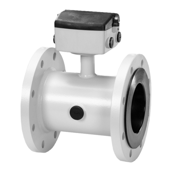
Description 3.3 Theory of operation Design The SITRANS FM MAG 5100 W is an electromagnetic flow sensor designed to meet the requirements in ground water, drinking water, waste water, sewage or sludge applications. With its coned design, increased low-flow accuracy is achieved making it especially useful for leak detection. - Page 21 Description 3.3 Theory of operation = When an electrical conductor of length L is moved at velocity v, perpendicular to the lines of flux through a magnetic field of strength B, the voltage U is induced at the ends of the conductor = L x B x v ●...
- Page 22 Description 3.3 Theory of operation SITRANS FM MAG 5100 W Operating Instructions, 01/2020, A5E03063678-AC...
-
Page 23: Installing/Mounting
Installing/Mounting SITRANS F flowmeters with minimum IP65/NEMA 4X enclosure rating are suitable for indoor and outdoor installations. ● Make sure that pressure and temperature specifications indicated on the device nameplate / label will not be exceeded. WARNING Installation in hazardous location Special requirements apply to the location and interconnection of sensor and transmitter. -
Page 24: Determining A Location
4.2 Determining a location Vibrations Avoid strong vibrations. Figure 4-1 Avoid vibrations CAUTION In applications with strong vibrations, Siemens recommends remote mounting of the transmitter! Determining a location Note The sensor must always be completely filled with liquid. Figure 4-2... - Page 25 Installing/Mounting 4.2 Determining a location ● Avoid the following installations – Installation at the highest point in the pipe system – Installation in vertical pipes with free outlet Figure 4-3 Wrong installation at high point Figure 4-4 Correct installation at low point before outlet Inlet and outlet conditions To achieve accurate flow measurement it is essential to have straight lengths of inlet and outlet pipes and a certain distance to pumps and valves.
- Page 26 Installing/Mounting 4.2 Determining a location Installation in partially filled pipes For partially filled pipes or pipes with downward flow and free outlet the flowmeter should be located in a U-tube. Installation in large pipes The flowmeter can be installed between two reducers (for example DIN 28545). At α ≤ 8° the following pressure drop curves apply.
-
Page 27: Orienting The Sensor
Installing/Mounting 4.3 Orienting the sensor Orienting the sensor The sensor operates in all orientations, but Siemens has the following recommendations: ● Vertical installation with an upwards flow Figure 4-6 Vertical orientation, upwards flow NOTICE Abrasive liquids / liquids containing solid particles... -
Page 28: Mounting
Installing/Mounting 4.4 Mounting Mounting ● Install the sensor in rigid pipelines in order to support the weight of the meter. ● Center the connecting pipelines axially in order to avoid turbulent flow profiles. ● Use proper gaskets according to liner type (not included). ①... - Page 29 Installing/Mounting 4.4 Mounting 1. Cross-tighten the bolts in the shown sequence. 2. Fasten bolts according to the torques values below. Note Torque values are calculated on the basis of use of gaskets. Table 4-1 Maximum allowable torques PN 6 PN 10 PN 16 PN 40 Class 150...
-
Page 30: Potential Equalization
Installing/Mounting 4.5 Potential equalization Torque calculations All values are theoretical and are calculated making the following assumptions: 1. All bolts are new and material selection is according to EN 1515-1 table 2. 2. Gasket material not exceeding 75 shore A durometer is used between the flowmeter and mating flanges. - Page 31 Installing/Mounting 4.5 Potential equalization Figure 4-9 Cathodic protection ● Isolate the sensor from cathodic protected pipes using insulated bolts. ● Use bypass cable between the mating flanges Note Remote mounted sensor versions If the above is not acceptable, remote mounted sensors can alternatively be connected as follows: ●...
- Page 32 Installing/Mounting 4.5 Potential equalization SITRANS FM MAG 5100 W Operating Instructions, 01/2020, A5E03063678-AC...
-
Page 33: Connecting
Connecting The following contains a short description of how to connect a remote mounted sensor to a transmitter type SITRANS FM MAG 5000 / 6000 or MAG 6000 I. For more information, e.g. about wiring of power supply and outputs, refer to the Operating Instructions for the respective transmitters. -
Page 34: Remote Installation
Connecting 5.1 Remote installation Cable specifications ● Only use cables with at least the same degree of protection as the sensor to install the sensor. ● The line length from the cable gland to the terminals must be kept as short as possible. Line loops in the terminal box must be avoided. - Page 35 Connecting 5.1 Remote installation 1. Unscrew and remove terminal box lid. ① 2. Mount the two terminal blocks as shown and insert electrode cable plug (terminals 82, ② 0 and 83) and coil cable plug (terminals 85 and 86). Terminals electrode cable: 82, 0 and 83 Terminals special electrode cable: 84, 83, 0, 82 and 81 Terminals coil cable: 85;...
- Page 36 Connecting 5.1 Remote installation 5. Fit and connect electrode and coil cables as shown below. Power supply Transmitter 115 to 230 V AC 11 to 30 V DC/11 to 24 V AC Outputs Current output (Powered from transmitter) 0/4 - 20 mA Load ≤...
-
Page 37: Installation Check
Connecting 5.2 Installation check CAUTION Unscreened cable ends Keep unscreened cable ends as short as possible. CAUTION Prevent interference Separate electrode and coil cables to prevent interference. WARNING Use in hazardous area Connect mains protective earth to the PE terminal in accordance with the above diagram in order to obtain potential equalization. -
Page 38: Potting
Connecting 5.3 Potting Before commissioning it must be checked that: ● The device has been installed and connected in accordance with the guidelines provided previous in this chapter and in Installing/Mounting (Page 23). Potting If sensor is buried or permanently submerged, terminal box must be encapsulated with silicon dielectric gel (non-toxic, transparent and self-healing gel). -
Page 39: Direct Burial
Connecting 5.4 Direct burial Direct burial Recommendations for direct burial of remote sensor: ● Check for visible damages in paint finish ! ● Use protection conduit ! ● Protect sensor with pea gravel at least 300 mm around sensor. This provides some drainage and also avoids caking sensor with earth. - Page 40 Connecting 5.4 Direct burial SITRANS FM MAG 5100 W Operating Instructions, 01/2020, A5E03063678-AC...
-
Page 41: Service And Maintenance
● Seal integrity of the process connections, cable entries, and cover screws ● Reliability of power supply, lightning protection, and grounds NOTICE Repair and service must be carried out by Siemens authorized personnel only. Note Siemens defines flow sensors as non-repairable products. - Page 42 Service and maintenance 6.2 Verification Figure 6-1 Example of a verification certificate SITRANS FM MAG 5100 W Operating Instructions, 01/2020, A5E03063678-AC...
-
Page 43: Recalibration
Service and maintenance 6.4 Technical support Recalibration Siemens Process Instrumentation offers to recalibrate the sensor. The following calibration types are offered as standard: ● Standard matched pair calibration ● Customer-specified calibration ● Accredited Siemens ISO/IEC 17025 calibration Note For recalibration the SENSORPROM unit must always be returned with the sensor. -
Page 44: Transportation And Storage
Service and maintenance 6.6 Return procedure Additional Support If you have additional questions about the device, please contact your local Siemens representative and offices at: Local contact person (http://www.automation.siemens.com/partner) Transportation and storage To guarantee sufficient protection during transport and storage, observe the following: ●... -
Page 45: Disposal
– Number of returned devices/replacement parts – Reason for returning the item(s) ● Decontamination declaration (http://www.siemens.com/sc/declarationofdecontamination) With this declaration you warrant "that the device/replacement part has been carefully cleaned and is free of residues. The device/replacement part does not pose a hazard for humans and the environment."... - Page 46 Service and maintenance 6.7 Disposal SITRANS FM MAG 5100 W Operating Instructions, 01/2020, A5E03063678-AC...
-
Page 47: Diagnostics And Troubleshooting
Diagnostics and Troubleshooting Sensor check Requirement To check the SITRANS FM sensors the following test instruments will be required: ● Digital Meter/Multimeter ● Megger ● (Moving Coil Meter) Sensor check Remove the transmitter from the sensor or remote position before making the following checks. Coil resistance check ●... -
Page 48: Fluctuating Process Values
Diagnostics and Troubleshooting 7.2 Fluctuating process values Electrode resistance check ● Measure the electrode resistance between connections 82 and 0 with a moving coil meter. With a sensor full of fluid the resistance should be between 5 KΩ and 50 KΩ. If the sensor is empty the resistance will be infinite. -
Page 49: Technical Data
Technical data MAG 5100 W Table 8-1 Technical data Version MAG 5100W (7ME6520) MAG 5100W (7ME6580) Product characteristic Mainly for the European market Mainly for the non-European market EPDM or NBR lining Ebonite lining Coned sensor: Full bore sensor: Design and nominal size ●... - Page 50 Technical data 8.1 MAG 5100 W Table 8-2 Process connections Version MAG 5100W (7ME6520) MAG 5100W (7ME6580) PN 10 (145 psi): EN 1092-1 Raised face (EN 1092-1, DIN 3501 and BS4504 ● DN 200 to 300 (8" to 12") have the same mating dimensions) Flat face flanges PN 16 (87 psi): PN 10 (145 psi):...
- Page 51 Technical data 8.1 MAG 5100 W Version MAG 5100W (7ME6520) MAG 5100W (7ME6580) Pressure drop DN 15 and 25 (½" and 1"): Insignificant ● Max. 20 mbar (0.29 psi) at 1 m/s (3 ft/ DN 40 to 300 (1½" to 12"): ●...
- Page 52 Technical data 8.1 MAG 5100 W Table 8-5 Certificates and approvals Version MAG 5100W (7ME6520) MAG 5100W (7ME6580) Calibration Zero-point, 2 x 25 % and 2 x 90 % Zero-point, 2 x 25 % and 2 x 90 % Standard production calibration, calibra‐ tion report shipped with sensor OIML R 49 pattern approval cold water Custody transfer (only with MAG...
-
Page 53: Cable Data
Technical data 8.2 Cable data Cable data Description Cable for standard electrode or coil Electrode cable, double shielded Cable kit with standard coil cable and electrode cable double shielded (also available as low noise cable for MAG 1100 sensor) Standard applications Table 8-6 Technical data, standard application cables Coil cable... -
Page 54: Effect Of Temperature On Working Pressure
Technical data 8.3 Effect of temperature on working pressure Coil cable Special electrode cable Cable parameter Capacity 161.50 pF/m Inductance 0.583 μH/m 43.83 þH/Ω Effect of temperature on working pressure Effect of temperature on working pressure. Table 8-8 Metric measures (pressure in bar) Flange specifi‐... -
Page 55: Process Fluid Conductivity
Technical data 8.4 Process fluid conductivity Process fluid conductivity Compact installation Liquids with an electrical conductivity ≥ 5 μS/cm. Remote installation Standard cable [µS/cm] Conductivity of medium [ft] Cabel length Special cable [µS/cm] Conductivity of medium 150 300 600 1200 1500 [ft] Cable length... -
Page 56: Liner Selection
Technical data 8.6 Electrode selection Liner selection Liner Applications EPDM Drinking water applications (not hydrocarbons) Ebonite Drinking water applications wastewater applications and cer‐ tain chemicals applications General purpose. Drinking water, sea waters Electrode selection Electrodes Hastelloy C The preferred choice for water and wastewater, chemicals, food and beverage, and pharmaceutical industries SITRANS FM MAG 5100 W Operating Instructions, 01/2020, A5E03063678-AC... -
Page 57: Sizing Tables
Technical data 8.7 Sizing tables Sizing tables Sizing table (DN 2 to DN 2000) SITRANS FM MAG 5100 W Operating Instructions, 01/2020, A5E03063678-AC... - Page 58 Technical data 8.7 Sizing tables Sizing table (DN " to DN 78") The tables show the relationship between flow velocity v, flow quantity Q and sensor dimension Guidelines for selection of sensor Min. measuring range: 0 to 0.25 m/s (0 to 0.8 ft/s) Max.
-
Page 59: Dimensions And Weight
Technical data 8.8 Dimensions and weight Flow velocity calculation formula: (metric measures) 1273.24 x Q [l/s] 353.68 x Q [m [m/s] or V = [m/s] [mm] [mm] (imperial measures) 0.408 x Q [GPM] 283.67 x Q [MGD] [ft/s] or V = [ft/s] (Pipe ID) [inch]... - Page 60 Technical data 8.8 Dimensions and weight Dimensions Table 8-10 Nominal size A Nominal size Order no. Order no. 7ME6520 NBR or EPDM liner 7ME6580 Ebonite liner inch inch inch ½ 1½ 2½ 10.0 10.9 10.1 12.0 11.2 13.1 12.2 14.1 15.0 14.3 16.0...
- Page 61 Technical data 8.8 Dimensions and weight Table 8-11 Nominal size L for 7ME6520 Nominal size PN 10 PN 16 PN 40 Class 150 AWWA C-207 AS 16 JIS10K inch inch inch inch inch inch inch inch ½ 1½ 2½ 11.8 11.8 11.8 11.8...
- Page 62 Technical data 8.8 Dimensions and weight Nominal size PN 6 PN 10 PN 16 PN 40 Class 150 AWWA AS 16 JIS10K C-207 inch inch inch inch inch inch inch inch inch 11.8 11.8 11.8 11.8 13.8 13.8 13.8 13.8 13.8 17.7 17.7...
- Page 63 Technical data 8.8 Dimensions and weight Weight Table 8-13 Weight for 7ME6520 Nominal size PN 10 PN 16 PN 40 Class 150 AWWA AS 16 JIS10K C-207 inch ½ 1½ 2½ 1069 1063 1074 645 1422 1000 1001 1482 1299 696 1534 1050 1528 N/A...
- Page 64 Technical data 8.8 Dimensions and weight Nominal PN 6 PN 10 PN 16 PN 40 Class 150 AWWA AS 16 JIS10K size C-207 inch 16.5 16.5 1043 N/A 1074 645 1000 40 1001 600 1321 N/A 1299 696 1050 42 1528 N/A 1100 44 1706 N/A...
-
Page 65: Product Documentation And Support
– "Download as html5, only PC": Open or save the manual in the HTML5 view on your PC You can also find manuals with the Mobile app at Industry Online Support (https:// support.industry.siemens.com/cs/ww/en/sc/2067). Download the app to your mobile device and scan the device QR code. Product documentation by serial number Using the PIA Life Cycle Portal, you can access the serial number-specific product information including technical specifications, spare parts, calibration data, or factory certificates. -
Page 66: Technical Support
In addition to our technical support, Siemens offers comprehensive online services at Service & Support (http://www.siemens.com/automation/service&support). Contact If you have further questions about the device, contact your local Siemens representative at Personal Contact (http://www.automation.siemens.com/partner). To find the contact for your product, go to "all products and branches" and select "Products &... -
Page 67: Appendix
Appendix Measuring ranges MAG 5100 W (7ME6520) MI-001 is verified and labeled at a given Q3 and Q3/Q4 = 1.25 and Q2/Q1 = 1.6 measuring ranges: Order code: P11 50 (2") 65 (2½") 80 (3") 100 (4") 125 (5") 150 (6") 200 (8") 250 (10") 300 (12") "R"... - Page 68 Appendix B.1 Measuring ranges Order code: P17 50 (2") 65 (2½") 80 (3") 100 (4") 125 (5") 150 (6") 200 (8") 250 (10") 300 (12") Q2 [m 0.32 0.50 0.80 1.28 12.8 Q1 [m 0.32 1.25 3.15 Order code: P18 50 (2") 65 (2½") 80 (3")
-
Page 69: Measuring Range According To En1434 (2007)
Appendix B.2 Measuring range according to EN1434 (2007) Order code: P29 700 (28") 750 (30") 800 (32") 900 (36") 1000 (40") 1200 (48") "R" Q Q4 [m 5000 5000 5000 7875 7875 7875 Q3 [m 4000 4000 4000 6300 6300 6300 Q2 [m 160.0... -
Page 70: Flange Mating Dimensions (Metric)
Appendix B.3 Flange mating dimensions (metric) 10.0 0.02 0.04 0.16 0.25 1.63 (1.25* Q 78.75 312.5 787.5 1250 2000 1000 1600 0.04 0.09 0.64 0.63 Flange mating dimensions (metric) Figure B-1 Flange mating dimensions Table B-1 Flange mating dimensions (metric) for 7ME6520 Dimensions (mm) Bolting Holes... - Page 71 Appendix B.3 Flange mating dimensions (metric) Dimensions (mm) Bolting Holes Bolts 1025 1125 1050 1000 1255 1170 1200 1485 1390 PN40 150 lb AWWA SITRANS FM MAG 5100 W Operating Instructions, 01/2020, A5E03063678-AC...
- Page 72 Appendix B.3 Flange mating dimensions (metric) Dimensions (mm) Bolting Holes Bolts 1060 1168 1086 1000 1289 1200 1050 1346 1257 1100 1403 1315 1200 1511 1422 AS 4087 PN16 1060 1175 1092 1000 1255 1175 1200 1490 1410 SITRANS FM MAG 5100 W Operating Instructions, 01/2020, A5E03063678-AC...
- Page 73 Appendix B.3 Flange mating dimensions (metric) Dimensions (mm) Bolting Holes Bolts Table B-2 Flange mating dimensions (metric) for 7ME6580 Dimensions (mm) Bolting Holes Bolts 1400 1630 1560 1500 1730 1660 1600 1830 1760 1800 2045 1970 2000 2265 2180 PN10 1015 1115 1050...
- Page 74 Appendix B.3 Flange mating dimensions (metric) Dimensions (mm) Bolting Holes Bolts 700 (WN) 1025 1125 1050 1000 1255 1170 1200 1485 1390 1400 1685 1590 1500 1820 1710 1600 1930 1820 1800 2130 2020 2000 2345 2230 PN40 150 lb AWWA 1061 1168...
- Page 75 Appendix B.3 Flange mating dimensions (metric) Dimensions (mm) Bolting Holes Bolts 1000 1289 1200 1050 1346 1257 1100 1403 1316 1200 1511 1422 1400 1683 1594 1500 1854 1759 1600 2032 1930 1800 2197 2096 2000 2362 2261 AS 4087 PN16 1060 1175 1092...
-
Page 76: Factory Settings
Appendix B.4 Factory settings Dimensions (mm) Bolting Holes Bolts Factory settings Dimension-dependent factory settings Table B-3 50 Hz version Qmax Unit Volume/ Pulse Totaliz‐ unit er unit Order no. 7ME6520 Order no. 7ME6580 pulse Inch Fac set‐ Min. Max. Min. Max. - Page 77 Appendix B.4 Factory settings Qmax Unit Volume/ Pulse Totaliz‐ unit er unit pulse Order no. 7ME6520 Order no. 7ME6580 1400 25000 1385.4 55417 1500 30000 1590.4 63617 1600 35000 1809.5 72382 1800 40000 2290.2 91608 2000 45000 2827.4 113097 Table B-4 60 Hz version Qmax Unit...
-
Page 78: Coil Resistance
Appendix B.5 Coil resistance Qmax Unit Volume/ Pulse Totaliz‐ unit er unit pulse Order no. 7ME6520 Order no. 7ME6580 1800 176115 10083.5 403341.5 US GPM 1000 US G US MG 2000 198129 12448.8 497952.5 US GPM 1000 US G US MG Coil resistance Table B-5 Coil resistance [Ω]... - Page 79 Appendix B.5 Coil resistance MAG 1100, MAG 1100 F MAG 3100, MAG 3100 P, MAG 5100 W MAG 5100 W (Order no. 7ME6580) (Order no. 7ME6520) 1600 1800 2000 On MAG 1100 DN 15 produced as of May 1999 the coil resistance must be 86 ohm, +8/−4 ohm. Note Reference values ●...
- Page 80 Appendix B.5 Coil resistance Description Terminal box, in stainless steel, inclusive of lid ½" NPT Potting kit for terminal box of MAG sensors for I P68/NEMA 6P (not for EX) SITRANS FM MAG 5100 W Operating Instructions, 01/2020, A5E03063678-AC...
-
Page 81: Certificates And Support
1. Scan the QR code on your device with a mobile device. 2. Click "PIA Portal". To display factory certificates, if available, log in to the PIA Life Cycle Portal using your login or register. See also Industry online support portal (http://www.siemens.com/processinstrumentation/certificates) SITRANS FM MAG 5100 W Operating Instructions, 01/2020, A5E03063678-AC... -
Page 82: Technical Support
In addition to our technical support, Siemens offers comprehensive online services at Service & Support. Contact If you have further questions about the device, contact your local Siemens representative at Personal Contact. To find the contact for your product, go to "all products and branches" and select "Products &... - Page 83 Glossary ASIC Application-Specific Integrated Circuit is an integrated circuit (IC) customized for a particular use, rather than intended for general-purpose use. Elex V Electromagnetic compatibility (EMC) is the branch of electrical sciences which studies the unintentional generation, propagation and reception of electromagnetic energy with reference to the unwanted effects (Electromagnetic Interference, or EMI) that such energy may induce.
- Page 84 Glossary USM II is a Communication Platform. The Siemens USM II concept enables fitting of add-on bus modules without loss of functionality: 1. All modules can be fitted as true "plug & play" 2. Module and transmitter are automatically configured through the SENSORPROM...
- Page 85 Index Abrasive liquids, 27 Hazardous area Add-on modules, (See Communication module) Approvals, 15 Applications, 19 Laws and directives, 11 Horizontal Pipes, 27 Hotline, 43, (Refer to Support request) Cable specifications, 34, 53 Catalog catalog sheets, 65, 81 Inlet / outlet conditions, 25 Cathodic protection, 30 Installation Certificates, 11, 65, 81...
- Page 86 Index Potential equalization, 30 Vertical Pipes, 27 Potting, 38 Vibrations, 24 Pressure Safety instructions, 23 Pressure Equipment Directive, 13 Process fluid Warranty, 9 Conductivity, 55 Weight, 63 Protective conductor terminal, 34 Wire insulation, 34 Protective earth, 34 Wiring, (See Electrical connection) QR code label, 82 Recalibration, 43 Repair, 41...
Need help?
Do you have a question about the SITRANS F Series and is the answer not in the manual?
Questions and answers