Siemens SITRANS F series Operating Instructions Manual
Coriolis flowmeters
mass 6000 ex d transmitter
Hide thumbs
Also See for SITRANS F series:
- Operating instructions manual (362 pages) ,
- Quick start manual (220 pages) ,
- Manual (188 pages)

Related Manuals for Siemens SITRANS F series


Summary of Contents for Siemens SITRANS F series
- Page 1 SITRANS F Coriolis Flowmeters MASS 6000 Ex d transmitter Operating Instructions Edition 08/2015 Answers for industry.
- Page 3 SITRANS F Coriolis flowmeters MASS 6000 Ex d transmitter Operating Instructions These Operating Instructions apply to Siemens products SITRANS MASS 6000 Ex d with order code commencing 7ME4110-2G, 7ME4110-2H, 7ME4110-2J. For use with sensor type MASS 2100 or FC300. 08/2015...
-
Page 4: Table Of Contents
SITRANS F C MASSFLO Contents Introduction ......................... 4 Installation ........................5 Compact ........................6 Remote ........................6 Ex survey according to Directive 94/9/EC (ATEX) ............6 Overview ........................7 2.5 Device identification..................... 8 Approvals ........................9 Special conditions for safe use of MASS 6000 Ex-d version and MASS 2100 ....9 Mounting of transmitter compact or remote ............... -
Page 5: Introduction
Installation of the equipment must comply with national regulations. Example EN 60079-14 for Denmark. • Repair and service can be done by approved Siemens Flow Instruments personnel only. • The p/T ratings indicate the relationship between the maximum allowable pressure PS and the maximum allowable temperature. -
Page 6: Installation
SITRANS F C MASSFLO 2. Installation Category 2 equipment Installation May be installed in zone 1 and zone 2. 2.1 Compact Category 1 equipment 2.2 Remote Sensor MASS 2100 may be installed in zone 0, zone 1 and zone 2. Catetory 2 equipment Transmitter MASS 6000 Ex-d may only be installed in zone 1 and zone 2. Horizontal mounting Mount the sensor on a vibration-free wall or steel frame as shown. -
Page 7: Ex Survey According To Directive 94/9/Ec (Atex)
SITRANS F C MASSFLO 2. Installation II 2G Ex ia IIC T5 as an example 2.3 Ex survey according to Directive 94/9/EC (ATEX) Instrument groups Applies to instruments used in underground mining operations, as well as their above ground operations, which can be endangered by mine gas and/or flammable dusts. -
Page 8: Overview
SITRANS F C MASSFLO 2. Installation A = Ex e (Increased safety) 2.4 Overview B = Ex ia (Intrinsic safety) MASS 6000 Ex-d Flameproof enlosure C = Ex d (Flameproof safety) Ex d e ib [ia Ga] IIC T4 Gb 1. -
Page 9: Device Identification
Code No. : 7ME4110-1FA21-1AA0 Serial No. : XXXXXXNXXX User Tag No. : XXXXXXXX Warning - Do not open when energized After de-energizing, wait 30 minutes before opening Siemens A/S Flow Instruments, 6400 Soenderborg, Denmark Made in France Meaning 1. Notified body for QA supervision: UL International DEMKO A/S, Denmark Explosion protected... -
Page 10: Approvals
SITRANS F C MASSFLO 2. Installation 2.6 Approvals Transmitter MASS 6000 Ex-d compact or remote mounted 0539 II 2 G DEMKO 03 ATEX 135253X Ex d e ib [ia Ga] IIC T4 Gb ambient temperature −20 to +50°C/−4°F to 122°F Directives EN 60079-0:2012+A11:2013 EN 60079-1:2007... -
Page 11: Mounting Of Transmitter Compact Or Remote
SITRANS F C MASSFLO 2. Installation 2.8 Mounting of transmitter For compact installation mount the transmitter compact or remote on top of the sensor interface. Please make sure that it is correctly oriented (note the little Compact Ex-d version tap). -
Page 12: Electrical Connection
SITRANS F C MASSFLO 3. Electrical connection Electrical connection Turn off the power supply before connecting input and output cables and wait 3.1 Electrical connection 30 minutes before unscrewing the lid. compact or remote Mounting and connection View A Ex e M20 black ATEX Ex-e approved gland, power supply cable "e". - Page 13 SITRANS F C MASSFLO 3. Electrical connection 3.1 Electrical connection compact or remote (continued) Important Electrical connections are made through the front of the transmitter (view A), in the terminal housing. This housing is accessed by removing the front cover described in chapter 2. Read the chapter 4.
-
Page 14: Setting Of Active Or Passive Current Out-Put Mode
SITRANS F C MASSFLO 3. Electrical connection 3.2 Setting of active or The current output in MASS 6000 can operate passive current out- in either active or passive mode to make put mode electrical connection as easy as possible. The current output in MASS 6000 is default set to active mode. -
Page 15: Installation Of Add-On Module (Aom)
SITRANS F C MASSFLO 3. Electrical connection 3.4 Installation of Disconnect the equipment from the supply add-on module (AOM) circuits and wait 30 min. for dischanging the energy in the internal electronics before opening. View C Remove the rear cover, by loosening the safety Ex d tap allen screw (M3) and turn the rear cover counter-clockwise. -
Page 16: Installation Examples
SITRANS F C MASSFLO 3. Electrical connection 3.5 Installation examples Current output in passive mode Frequency/pulse output in passive mode HART output Intrinsically safe data "ia", please look into the "Technical data" in chapter 4. A5E02944883-AA... -
Page 17: Technical Data
4. Technical data SITRANS F C MASSFLO Technical data 4.1 Transmitter MASS 6000 Ex-d MASS 6000 Ex-d Measurement of Mass flow [kg/s (lb/s)], volume flow [l/s (g/s)], fraction [%], Brix, density [kg/m (lb/ft ], temperature [°C (°F)] Current output Classified Ex ia, selectable as active or passive outputs. Default setting is passive mode Current 0-20 mA or 4-20 mA < 350 ohm Load Time constant 0.1-30 s adjustable Output characteristics Active mode (read note 1) -
Page 18: Transmitter Mass 6000 Ex-D
5 or [µH/Ω] [nF] 1410 1410 Cable between sensor and Maximum distance between sensor and transmitter MASS 6000 is 300 m with Siemens Flow MASS 6000 Instruments cable FDK:083H3005 or FDK:083H3006 or equivalent cable. Cable data Capacitance 300 [pF/m] 1 [µH/m]... - Page 19 SITRANS F C MASSFLO 4. Technical data Intrinsic safe terminals in the connections room are in general evaluated as „ia“ for gas group IIC. The output terminals 31-32 is set in „active mode“ which means that it can be connected to other intrinsic safe product, which match the output specification, please look at the specification and the note 1.
-
Page 20: Output Characteristic Mass 6000 Ex-D
SITRANS F C MASSFLO 4. Technical data 4.2 Output characteristic Output Bidirectional mode Unidirectional mode MASS 6000 Ex-d characteristics 0-20 mA 4-20 mA Frequency Pulse output Relay Power supply off Power supply on Error relay No error Error Limit switch or 1 set point 2 set points direction switch... -
Page 21: Commissioning
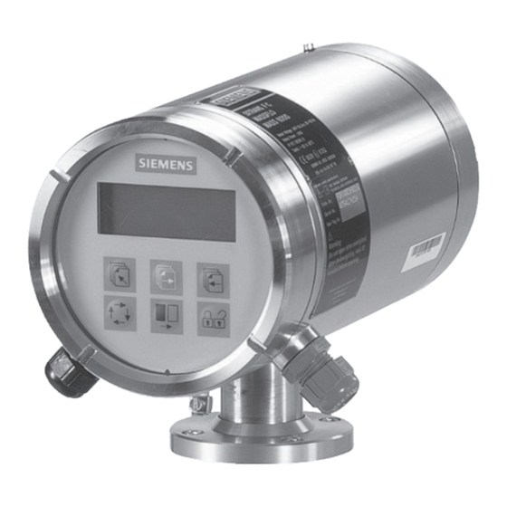
SITRANS F C MASSFLO 5. Commissioning Commissioning Keypad and display layout Keypad The keypad is used to set the flowmeter. The function of the keys are as follows: TOP UP KEY This key (hold 2 sec.) is used to switch between operator menu and setup menu. In the transmitter setup menu, a short press will cause a return to the previous menu. FORWARD KEY This key is used to step forward through the menus. -
Page 22: Menu Build-Up
SITRANS F C MASSFLO 5. Commissioning Menu build-up The menu structure of a specific type of transmitter is shown in a menu overview map. Details of how a specific parameter is set is shown in a menu detail map for the specific param- eter. The menu structure is valid for the title and subtitle line only. The upper line is for primary readings only and will always be active with either mass flowrate, volume flowrate, density, temperature, totalizer 1 or totalizer 2. The menu is built up in two parts. An operator menu and a setup menu. Operator menu The operator menu is for daily operation. -
Page 23: Menu Overview
SITRANS F C MASSFLO 5. Commissioning 5.3 Menu overview A5E02944883-AA... -
Page 24: Menu Details
SITRANS F C MASSFLO 5. Commissioning 5.4 Menu details Basic settings menu The decimal point for flowrate, totalizer 1 and totalizer 2 can be individually positioned. • open the respective window. • ensure that the cursor is positioned below the decimal point. Use the SELECT KEY . • move the comma to the required position. Use the CHANGE KEY . Units are changed by means of the CHANGE KEY with the cursor placed below the unit selected. Select units (moving the cursor) by means of the SELECT KEY Totalizer 2 is not visible when batch is selected as digital output. A5E02944883-AA... -
Page 25: Outputs Setting Menu
SITRANS F C MASSFLO 5. Commissioning 5.5 Outputs setting menu Current output The current output must be set off when not used. Digital output Pulse Digital output Frequency A5E02944883-AA... - Page 26 5. Commissioning SITRANS F C MASSFLO Digital output Batch Relay output Error level (Also possible through digital output) Acceptance level is set in the basic settings menu. Error number (Also possible through digital output) Limit switch & direction switch (Also possible through digital output) Direction flow: Select 1 setpoint at zero flow; Hysteresis at 5 %.
-
Page 27: Reset Mode
Adjust. The value Zero Sigma shows the standard deviation of the individual measurements made. The standard deviation (Zero Sigma) must be within a window, which is predefined by Siemens Flow Instruments . This window is called Sigma Limit. If the standard deviation is outside the window the following mes- sage is shown in the display: “Zero Sigma exceeds Sigma Limit”. In this case check the installation, ensure that the pipe is full and that there is absolute 0-flow present. Then repeat the 0-point... -
Page 28: Service
SITRANS F C MASSFLO 6. Service Service Error Error text #Comment Outputs Input 6.1 List of error numbers Remedy text status status I1 - Power on Power on has activated Active Active I2 - Add-on module Applied A new module has been added to the system Active Active I3 - Add-on module... -
Page 29: Trouble Shooting Mass 6000 Ex-D
SITRANS F C MASSFLO 6. Service 6.2 Trouble shooting Symptom Output Error Cause Remedy MASS 6000 Ex-d signals code Empty display Minimum 1. Supply voltage 1. Check supply voltage 2. MASS 6000 defective 2. Replace MASS 6000 No flow signal Minimum 1. -
Page 30: Ordering
SITRANS F C MASSFLO 7. Ordering Ordering Description Version Supply voltage Order no. Symbol 7.1 Transmitter MASS 6000 transmitter 1 current output 24 V AC/DC MASS 6000 Ex-d for Ex-d inclusive wall 1 frq./pulse output remote mounting mounting kit with 5 m 1 relay output (16.4 ft) sensor cable 7ME4110-2GA21-1AA1... - Page 31 For more information www.siemens.com/flow Siemens A/S Subject to change without prior notice Flow Instruments Order No.: A5E02944883 Coriolisvej 1-3 Lit. No.: A5E02944883-AA DK-6400 Soenderborg © Siemens AG 08/2015 A5E02944883 www.siemens.com/processautomation...
Need help?
Do you have a question about the SITRANS F series and is the answer not in the manual?
Questions and answers