Siemens SITRANS F Series Operating Instructions Manual
Coriolis flowmeters
Hide thumbs
Also See for SITRANS F Series:
- Operating instructions manual (362 pages) ,
- Quick start manual (220 pages) ,
- Manual (188 pages)
Table of Contents
Advertisement
Quick Links
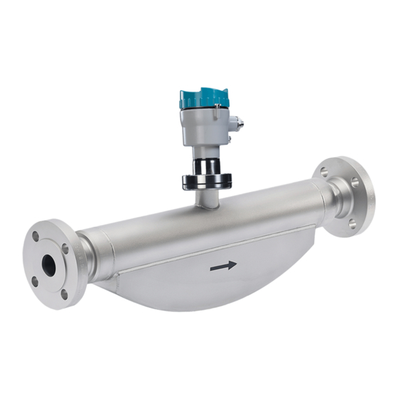
SITRANS F
Coriolis Flowmeters
FC310 (From firmware 4.0)
Operating Instructions
These Operating Instructions apply to Siemens
products SITRANS FC310 with order codes
commencing 7ME
06/2018
A5E44036384-AA
Introduction
Safety notes
Description
Installing/mounting
Connecting
Commissioning
Operating
Parameter assignment
Service and maintenance
Diagnostics and
troubleshooting
Technical data
Dimension drawings
Technical reference
Modbus communication
Remote operation
Certificates and support
1
2
3
4
5
6
7
8
9
10
11
12
A
B
C
D
Advertisement
Table of Contents
Troubleshooting

Subscribe to Our Youtube Channel
Related Manuals for Siemens SITRANS F Series


Summary of Contents for Siemens SITRANS F Series
- Page 1 Operating Instructions Operating Parameter assignment Service and maintenance Diagnostics and troubleshooting Technical data Dimension drawings Technical reference Modbus communication These Operating Instructions apply to Siemens products SITRANS FC310 with order codes Remote operation commencing 7ME Certificates and support 06/2018 A5E44036384-AA...
- Page 2 Note the following: WARNING Siemens products may only be used for the applications described in the catalog and in the relevant technical documentation. If products and components from other manufacturers are used, these must be recommended or approved by Siemens. Proper transport, storage, installation, assembly, commissioning, operation and maintenance are required to ensure that the products operate safely and without any problems.
-
Page 3: Table Of Contents
Table of contents Introduction..............................7 FC310 manual usage.......................7 Purpose of this documentation....................7 Document history........................7 Product compatibility........................8 Device documentation package....................8 Items supplied..........................9 Checking the consignment.......................9 Security information.......................10 Transportation and storage....................11 1.10 Notes on warranty........................11 Safety notes..............................13 Preconditions for use......................13 2.1.1 Warning symbols on the device.....................13 Laws and directives........................14 2.2.1 Conformity with European directives..................15... - Page 4 Table of contents Installation instructions......................32 4.2.1 Orientation of the sensor......................33 4.2.2 Mounting the sensor.......................36 4.2.3 Hydrostatic testing........................38 4.2.4 Installing with insulation......................38 Disassembly...........................39 Connecting..............................41 Basic safety notes........................41 Connecting the FC310......................45 5.2.1 Warnings..........................45 Nameplates for hazardous area installations.................49 5.3.1 Device identification.......................49 Instructions specific to hazardous area installations..............55 Commissioning............................57 Basic safety notes........................57 Remote commissioning......................60...
- Page 5 Table of contents Alarm messages........................93 Service and maintenance...........................97 Ordering of spare parts......................97 Basic safety notes........................97 Recalibration..........................98 Cleaning..........................99 Maintenance and repair work....................99 9.5.1 Service information........................99 9.5.2 Ex approved products......................102 Replacing the device......................103 Transport..........................103 Return procedure.........................103 Disposal..........................104 Diagnostics and troubleshooting......................105 10.1 Device status symbols......................105 10.1.1 Device status symbols (chart)....................105 10.1.2...
- Page 6 Table of contents 11.8.2 Pressure drop curves......................161 Dimension drawings..........................163 12.1 Sensor dimensions.......................163 12.2 316L stainless steel - standard....................164 12.3 316L stainless steel - NAMUR.....................170 12.4 Hygienic versions.........................170 Technical reference..........................175 Theory of operation......................175 Sensor dimension dependent default settings..............176 A.2.1 Sensor dimension dependent default settings (Process values).........176 A.2.2 Sensor dimension dependent default settings (Process values).........177 A.2.3...
-
Page 7: Introduction
FC310 manual usage Note This manual applies to the Coriolis flowmeter SITRANS FC310 This document are standard delivered in electronic media with the device. Latest version can be downloaded at www.siemens.com (http://support.automation.siemens.com/WW/view/en/ 60666565/134200) Purpose of this documentation These instructions contain all information required to commission and use the device. Read the instructions carefully prior to installation and commissioning. -
Page 8: Product Compatibility
Introduction 1.5 Device documentation package NOTICE Use in a domestic environment This Class A Group 1 equipment is intended for use in industrial areas. In a domestic environment this device may cause radio interference. Product compatibility Manual Remarks Device revision Compatibility of device integration package edition 06/2018... -
Page 9: Items Supplied
Introduction 1.7 Checking the consignment Items supplied With M12 plug connection ● SITRANS FC310 flowmeter ● Sensor cable with M12 connector ● SD card with production certificates ● DVD containing software, certificates and device manuals With sensor terminal housing ● SITRANS FC310 flowmeter ●... -
Page 10: Security Information
In order to protect plants, systems, machines and networks against cyber threats, it is necessary to implement – and continuously maintain – a holistic, state-of-the-art industrial security concept. Siemens’ products and solutions only form one element of such a concept. Customer is responsible to prevent unauthorized access to its plants, systems, machines and networks. -
Page 11: Transportation And Storage
The content reflects the technical status at the time of publishing. Siemens reserves the right to make technical changes in the course of further development. - Page 12 Introduction 1.10 Notes on warranty FC310 (From firmware 4.0) Operating Instructions, 06/2018, A5E44036384-AA...
-
Page 13: Safety Notes
Safety notes Preconditions for use This device left the factory in good working condition. In order to maintain this status and to ensure safe operation of the device, observe these instructions and all the specifications relevant to safety. Observe the information and symbols on the device. Do not remove any information or symbols from the device. -
Page 14: Laws And Directives
Improper device modifications Danger to personnel, system and environment can result from improper modifications to the device. ● Changes or modifications not expressly approved by Siemens could void the user’s authority to operate the equipment. FC310 (From firmware 4.0) Operating Instructions, 06/2018, A5E44036384-AA... -
Page 15: Conformity With European Directives
Safety notes 2.2 Laws and directives Note ● This equipment has been tested and found to comply with the limits for a Class A digital device, pursuant to Part 15 of the FCC Rules. These limits are designed to provide reasonable protection against harmful interference when the equipment is operated in a commercial environment. -
Page 16: Requirements For Special Applications
If you need additional information not covered by these instructions, contact your local Siemens office or company representative. Note Operation under special ambient conditions... -
Page 17: Use In Hazardous Areas
● EN/IEC 60079-14 is considered for installation in hazardous areas. Further information and instructions including approval-specific special conditions for safe use in Ex applications can be found in the certificates on the accompanying literature CD and at the product web page (www.siemens.com/FC410). WARNING Laying of cables... -
Page 18: Installation In Hazardous Areas
Safety notes 2.4 Use in hazardous areas WARNING Use in hazardous area Risk of explosion. ● Only use equipment that is approved for use in the intended hazardous area and labelled accordingly. ● Don't use devices that have been operated outside the conditions secified for hazardous areas. -
Page 19: Maximum Temperature Specifications For Ex Use
Safety notes 2.4 Use in hazardous areas Installation variations Note Requirements for safe installation ● Remote sensor FCS300 can be installed in Zone 1, Div. 1 as Intrinsically Safe or Flameproof. ● Standard remote installation with FCT030 because the connection is certified Intrinsically Safe. - Page 20 Safety notes 2.4 Use in hazardous areas Ta (°C) Maximum Process Temperature per Temperature Class (°C) Additionally, the maximum surface temperature of the overall device shall be: ● If Tprocess ≤ 85°C, maximum surface temperature = 85°C. ● If Tprocess > 85°C, maximum surface temperature = process temperature. For installation in environment with max 500 mm dust, the maximum process temperature shall be as follows: Ta (°C)
-
Page 21: Description
Description Overview SITRANS Coriolis flow meter systems consist of a transmitter and a sensor. The following table lists the available combinations of transmitters and sensors. Transmitter Sensor type FCT010 FCS300 DN 15 to DN 150 (0.5" to 6") System integration The FC310 flowmeter functions as a Modbus RTU slave with standard Modbus commands implemented. - Page 22 Description 3.3 Design Figure 3-2 Flowmeter – terminated cable Flowmeter design All primary process measurement of massflow, volumeflow, density and process temperature are done in FC310 transmitter. The sensor comprises two parallel bent tubes welded directly to the process connections at each end via a manifold.
-
Page 23: Approvals
Description 3.5 Features Approvals Note For further details see Approvals (Page 151). The device is available with approvals for general purpose and for hazardous areas. In all cases, check the nameplate on your device, and confirm the approval rating. Features ●... -
Page 24: Applications
Description 3.8 Modbus RTU technology ● Intelligent filtering system for aerated flow ● Unit selection of process values and totalizer Applications Measurement of liquids and gases SITRANS F C Coriolis mass flowmeters are designed for measurement of a variety of liquids and gases. - Page 25 Description 3.8 Modbus RTU technology Features The SITRANS F Modbus RTU communication complies with the Modbus Serial Line Protocol. Among other things this implies a master / slave protocol at level 2 of the OSI model. A node (the master) issues explicit commands to one of the slave nodes and processes responses. Slave nodes will not transmit data without a request from the master node, and do not communicate with other slaves.
- Page 26 Description 3.8 Modbus RTU technology FC310 (From firmware 4.0) Operating Instructions, 06/2018, A5E44036384-AA...
-
Page 27: Installing/Mounting
Refer to the information in Technical data (Page 145). Note Material compatibility Siemens can provide you with support concerning selection of sensor components wetted by process media. However, you are responsible for the selection of components. Siemens accepts no liability for faults or failures resulting from incompatible materials. - Page 28 Installing/mounting 4.1 Basic safety notes WARNING Exceeded maximum permissible operating pressure Risk of injury or poisoning. The maximum permissible operating pressure depends on the device version, pressure limit and temperature rating. The device can be damaged if the operating pressure is exceeded. Hot, toxic and corrosive process media could be released.
-
Page 29: Installation Location Requirements
Installing/mounting 4.1 Basic safety notes 4.1.1 Installation location requirements WARNING Insufficient air supply The device may overheat if there is an insufficient supply of air. ● Install the device so that there is sufficient air supply in the room. ● Observe the maximum permissible ambient temperature. Refer to the information in the section Technical data (Page 145). - Page 30 Installing/mounting 4.1 Basic safety notes NOTICE Incorrect mounting The device can be damaged, destroyed, or its functionality impaired through improper mounting. ● Before installing ensure there is no visible damage to the device. ● Make sure that process connectors are clean, and suitable gaskets and glands are used. ●...
- Page 31 Installing/mounting 4.1 Basic safety notes Avoid vibrations ● Make sure that any valves or pumps upstream of the sensor do not cavitate and do not send vibrations into the sensor. ● Decouple vibrating pipeline from the flow sensor using flexible tube or couplings. Figure 4-1 Non-flexible pipes not recommended in vibrating environment Figure 4-2...
-
Page 32: Installation Instructions
Installing/mounting 4.2 Installation instructions Installation instructions WARNING High pressure hazard In applications with working pressures/media that can be dangerous to people, surroundings, equipment or others in case of pipe fracture, we recommend that special precautions such as special placement, shielding or installation of a pressure guard or a safety valve are taken when the flowmeter is mounted. -
Page 33: Orientation Of The Sensor
Installing/mounting 4.2 Installation instructions Location in the system The optimum location in the system depends on the application: ● Liquid applications Gas or vapor bubbles in the fluid may result in erroneous measurements, particularly in the density measurement. – Do not install the flowmeter at the highest point in the system, where bubbles will be trapped. - Page 34 Installing/mounting 4.2 Installation instructions NOTICE Orienting the sensor To avoid water or moist ingress, transmitters should be oriented with cable entrances aiming downwards. FC310 (From firmware 4.0) Operating Instructions, 06/2018, A5E44036384-AA...
- Page 35 Orienting the sensor The sensor operates in any orientation. The optimal orientation depends on the process fluid and the process conditions. Siemens recommends orienting the sensor in one of the following ways: 1. Vertical installation with an upwards flow (self-draining)
-
Page 36: Mounting The Sensor
Installing/mounting 4.2 Installation instructions Installation in a drop line Installation in a drop line is only recommended if a pipeline reduction or orifice with a smaller cross-section can be installed to create back-pressure and prevent the sensor from being partially drained while measuring. ①... - Page 37 Installing/mounting 4.2 Installation instructions Avoid vibrations ● Make sure that any valves or pumps upstream of the sensor do not cavitate and do not send vibrations into the sensor. ● Decouple vibrating pipeline from the flow sensor using flexible tube or couplings. Figure 4-11 Non-flexible pipes not recommended in vibrating environment Figure 4-12...
-
Page 38: Hydrostatic Testing
Installing/mounting 4.2 Installation instructions 4.2.3 Hydrostatic testing The flowmeter is pressure-tested before delivery to 1.5 times the rated working pressure of the sensor. In all cases the maximum allowed hydrostatic test pressure (MATP) of the flowmeter is 1.5 times the marked MAWP (PS) at 20 °C. Pressure test of a completed flow system with piping and other components can be done at pressures no higher than 1.5 times the marked MAWP (PS) at 20 °C of the lowest rated system component. -
Page 39: Disassembly
Installing/mounting 4.3 Disassembly Disassembly WARNING Incorrect disassembly The following risks may result from incorrect disassembly: - Injury through electric shock - Risk through emerging media when connected to the process - Risk of explosion in hazardous area In order to disassemble correctly, observe the following: ●... - Page 40 Installing/mounting 4.3 Disassembly FC310 (From firmware 4.0) Operating Instructions, 06/2018, A5E44036384-AA...
-
Page 41: Connecting
Connecting Basic safety notes Use in hazardous areas Before accessing the sensor terminal compartment and application terminal space check that: ● A safe access permission certificate has been issued by plant operations management ● The flow transmitter may not be opened if energized ●... - Page 42 Connecting 5.1 Basic safety notes WARNING Incorrect conduit system Risk of explosion in hazardous areas as result of open cable inlet or incorrect conduit system. ● In the case of a conduit system, mount a spark barrier at a defined distance from the device input.
- Page 43 Connecting 5.1 Basic safety notes WARNING Lack of equipotential bonding Risk of explosion through compensating currents or ignition currents through lack of equipotential bonding. ● Ensure that the device is potentially equalized. Exception: It may be permissible to omit connection of the equipotential bonding for devices with type of protection "Intrinsic safety Ex i".
- Page 44 Connecting 5.1 Basic safety notes WARNING Insufficient isolation of intrinsically safe and non-intrinsically safe circuits Risk of explosion in hazardous areas. ● When connecting intrinsically safe and non‑intrinsically safe circuits ensure that isolation is carried out properly in accordance with local regulations for example IEC 60079-14. ●...
-
Page 45: Connecting The Fc310
Connecting 5.2 Connecting the FC310 NOTICE Condensation in the device Damage to device through formation of condensation if the temperature difference between transportation or storage and the mounting location exceeds 20 °C (36 °F). ● Before taking the device into operation let the device adapt for several hours in the new environment. - Page 46 Connecting 5.2 Connecting the FC310 Note End Of Line (EOL) termination The FCT010 EOL termination DIP switch is default set to EOL active. To change termination setting see Warnings (Page 45). It is important to terminate the Modbus RS 485 line correctly at the start and end of the bus segment since impedance mismatch results in reflections on the line which can cause faulty communication transmission.
- Page 47 It is recommended to use cables supplied by Siemens A/S, Flow Instruments. ● Siemens supplied cables can be ordered with M12 plug on both ends or without plug. ● To guarantee the IP67 degree of protection, ensure that both ends of the cables are given equivalent protection from ingress of moisture.
- Page 48 6. Push the cable through the open gland and anchor the cable shield and the wires with the clamp bar. 7. Remove the terminal block from the electronic. 8. Connect the wires to the terminals according to the list below. Terminal number Description Wire color (Siemens cable) Orange Yellow RS485 / B White RS485 / A...
-
Page 49: Nameplates For Hazardous Area Installations
Connecting 5.3 Nameplates for hazardous area installations 10.Connect the sensor connection and the sensor cable. 11.Restore the flexible strap around all wires. 12.Assemble and tighten the cable gland. 13.Remove the O-ring from lid. 14.Reinstate the lid and screw in until the mechanical stop. Wind back the lid by one turn. 15.Mount the O-ring by pulling it over the lid and tighten the lid until you feel friction from the O-ring on both sides. - Page 50 Connecting 5.3 Nameplates for hazardous area installations FCT010 transmitter identification nameplate ① Product name Transmitter product name ② System revisions System revision numbers; firmware (FW) and hardware (HW) ③ Consult the operating instructions ④ WEEE ⑤ Enclosure IP Degree of protection ⑥...
- Page 51 The flowmeter serial number is constructed as follows: PPPYMDDxxxxxx where PPP = Production factory (Siemens Flow Instruments: FDK) Y = Production year (for encryption, see below) M = Production month (for encryption, see below) DD = Production date (for encryption, see below)
- Page 52 Ex approval specifications for the transmitter (ATEX example; for details on all approvals) Figure 5-6 FCT010 transmitter specification nameplate Note Approval identifications Approval certificates and notified body identifications are available for download at www.siemens.com. FC310 (From firmware 4.0) Operating Instructions, 06/2018, A5E44036384-AA...
- Page 53 Connecting 5.3 Nameplates for hazardous area installations FCS300 sensor specification nameplate APPROVED ā ā ³ ① Ex approvals Ex approval specifications for the sensor ② Consult the operating instructions ③ Year of Manufac‐ Manufacturing year ture More detailed manufacturing date information is given in the serial number found on the identification nameplate ④...
- Page 54 Connecting 5.3 Nameplates for hazardous area installations FCS300 sensor approval nameplate ① QR code Product-specific QR code ② C✓ C-tick logo ③ 3A logo ④ WEEE symbol Note Logos and warnings Logos and warnings are only shown on the product where applicable. The combination shown in the example above is relevant for a hygienic sensor installed in hazardous area in Canada.
-
Page 55: Instructions Specific To Hazardous Area Installations
Connecting 5.4 Instructions specific to hazardous area installations Instructions specific to hazardous area installations Hazardous area applications Special requirements apply to the location and interconnection of sensor and transmitter. See Use in hazardous areas (Page 17). WARNING Transmitter housing Before opening the terminal box check that: ●... - Page 56 Connecting 5.4 Instructions specific to hazardous area installations FC310 (From firmware 4.0) Operating Instructions, 06/2018, A5E44036384-AA...
-
Page 57: Commissioning
Commissioning Basic safety notes DANGER Toxic gases and liquids Danger of poisoning when venting the device: if toxic process media are measured, toxic gases and liquids can be released. ● Before venting ensure that there are no toxic gases or liquids in the device, or take the appropriate safety measures. - Page 58 Commissioning 6.1 Basic safety notes WARNING Hazardous contact voltage Risk of injury through hazardous contact voltage when the device is open or not completely closed. The degree of protection specified on the nameplate or in Technical data (Page 145) is no longer guaranteed if the device is open or not properly closed.
- Page 59 Commissioning 6.1 Basic safety notes WARNING Unsuitable safety system for the pressurized enclosure in Zone 2 Risk of explosion in areas subject to explosion hazard. ● If no combustible gases or gas/air mixtures (sample gases) are introduced into the device, use the type of protection "Simplified pressurized enclosure Ex pz"...
-
Page 60: Remote Commissioning
Operating via SIMATIC PDM SIMATIC PDM is a software package used to commission and maintain process devices. See also www.siemens.com/simatic-pdm (www.siemens.com/simatic-pdm) 6.2.1.2 Functions in SIMATIC PDM SIMATIC PDM monitors the process values, alarms and status signals of the device. It allows you to display, compare, adjust, verify, and simulate process device data;... -
Page 61: Initial Setup
This deactivation is required to align SIMATIC PDM with the Modbus modem for Windows ® operating systems. Note Support for Windows operating systems can be found here: support.automation.siemens.com (http://support.automation.siemens.com) 1. Click Start → Control Panel to begin configuration. 2. Click on Hardware and Sound and then on Device Manager. - Page 62 You can locate the EDD in the SIMATIC PDM Device Library under Devices → Modbus → Sensors → Flow → Coriolis → Siemens AG → SITRANS FC. Check the product page of our website at: (www.siemens.com/FC410), under Downloads, to make sure you have the latest version of SIMATIC PDM, the most recent Service Pack (SP) and the most recent hot fix (HF).
-
Page 63: Adding Device To Communication Network
– Right-click Modbus Network and select Insert New Object → Object. – Click on Assign Device Type, and select Devices → Modbus → Sensors → Flow → Coriolis → SIEMENS AG → SITRANS FC Click OK two times. Figure 6-1 Assigning Modbus device to network 2. -
Page 64: Configuring A New Device
Commissioning 6.2 Remote commissioning – Select the Communication tab and configure the communication parameters. The transmitters default settings are: - Transmission rate: 19200 baud - Parity: even Figure 6-2 Modbus net object properties – Click OK. 3. Set up the COM interface: –... -
Page 65: Wizard - Quick Start Via Pdm
Commissioning 6.2 Remote commissioning 1. Check that you have the most recent EDD, and if necessary update it, see Updating the Electronic Device Description (EDD) in Initial setup (Page 61). 2. Launch SIMATIC Manager. 3. Right-click on SITRANS FC and select Open Object to open SIMATIC PDM. 4. - Page 66 Commissioning 6.2 Remote commissioning Step 1 - Identification Note The layout of the dialog boxes shown may vary according to the resolution setting for your computer monitor. The recommended resolution is 1280 x 960. FC310 (From firmware 4.0) Operating Instructions, 06/2018, A5E44036384-AA...
- Page 67 Commissioning 6.2 Remote commissioning 1. Click on Read Data from Device to upload Quick Start parameter settings from the device to the PC/PG and ensure PDM is synchronized with the device. 2. Click on Next to accept the default values. (Descriptor, Message, and Date fields can be left blank.) Figure 6-4 Quick start step 1...
- Page 68 Commissioning 6.2 Remote commissioning Step 2 - Sensor orientation Step 2 shows an overview of the various recommended installation orientations depending on the application. Figure 6-5 Quick start step 2 FC310 (From firmware 4.0) Operating Instructions, 06/2018, A5E44036384-AA...
- Page 69 Commissioning 6.2 Remote commissioning Step 3 - Sensor connection The transmitter can be ordered with M12 connection or with terminated cable (for example conduit connections). Figure 6-6 Quick start step 3 FC310 (From firmware 4.0) Operating Instructions, 06/2018, A5E44036384-AA...
- Page 70 Commissioning 6.2 Remote commissioning Step 4 - Measurement conditions Configure the measurement conditions for the selected process variables. Change Flow Direction if necessary. Figure 6-7 Quick start step 4 Reduce the sensitivity of the flow measurement signal by clicking on the Pulsating Flow button and selecting the appropriate filter.
- Page 71 Commissioning 6.2 Remote commissioning Figure 6-8 Filter setting selection Step 5 - Summary Check parameter settings, and click on Back to return and revise values, Apply to save settings offline, or Apply and Transfer to save settings offline and transfer them to the device. Figure 6-9 Quick start step 5 The message Quick Start was successful will appear.
-
Page 72: Wizard - Zero Point Adjustment
Commissioning 6.2 Remote commissioning See also Configuring a new device (Page 64) 6.2.1.8 Wizard - Zero Point adjustment Open the menu Device → Wizard → Zero Point Adjustment. Select Auto. Click on Next. It is recommended to use the default settings. Change the Zero Point Adjustments Settings, if necessary. -
Page 73: Changing Parameter Settings Using Simatic Pdm
Commissioning 6.2 Remote commissioning 6.2.1.9 Changing parameter settings using SIMATIC PDM Note Clicking on Cancel during an upload from device to SIMATIC PDM will result in some parameters NOT being updated. FC310 (From firmware 4.0) Operating Instructions, 06/2018, A5E44036384-AA... -
Page 74: Parameters Accessed Via Drop-Down Menus
Commissioning 6.2 Remote commissioning Many parameters are accessed via the online menus in PDM, see Parameters accessed via drop-down menus (Page 74) for the others. 1. Launch SIMATIC PDM, connect to the appropriate device and upload data. 2. Adjust parameter values in the parameter value field then click on Enter. The status fields read Changed. -
Page 75: Zero Point Adjustment
Commissioning 6.2 Remote commissioning Drop-down menus Table 6-1 Device menus Device menus Description Download to Device Downloads all writable parameters to the device Upload to PC/PG Uploads all parameters from the device to the parameter table Assign address and TAG Assign communication address and TAG name Value comparison Compare values between device / project... - Page 76 Commissioning 6.2 Remote commissioning 1. Flush out the flowmeter until a homogenous flow is established and the tubes completely filled. Figure 6-10 Best practice zero point adjustment with a by-pass line and two shut-off devices 2. Establish zero flow for example by closing the shut off-valves. 3.
-
Page 77: Process Variables
Commissioning 6.2 Remote commissioning 6. During the process a progress bar is visible. 7. At the end of the zero adjustment, the outcome is displayed as an offset and a standard deviation. Note If you get an error message after the zero point adjustment, refer to Device status symbols (Page 105). - Page 78 Commissioning 6.2 Remote commissioning FC310 (From firmware 4.0) Operating Instructions, 06/2018, A5E44036384-AA...
-
Page 79: Operating
Operating Operating instructions 7.1.1 Remote operation 7.1.1.1 Modbus addressing model The device allows read/write access to the following standard Modbus RTU data holding register blocks: ● Holding registers (ref. 4x address range) The minimum value of a writable holding register can be read by adding 10000 to the Modbus address of the register. - Page 80 Operating 7.1 Operating instructions Holes/register alignment: ● The read command always returns data if no exception is given. ● Holes in the holding register map return value zero in all bytes. E.g. reading 2 registers starting at 4:0004 above will result in 2 bytes of "float B" followed by 2 zeroes. Function code 3 example Query Slave address...
- Page 81 Operating 7.1 Operating instructions Absolute mass flow = 0x40C35293 = 6.10383 kg/sec Function code 16 (Write multiple registers) General exceptions ● Writing less than 1 or more than 16 registers => Exception 3 (Illegal data value) ● If ByteCount is not exactly 2 times NoOfRegisters => Exception 3 (Illegal data value) ●...
- Page 82 Operating 7.1 Operating instructions Response Slave address 1 byte Function 1 byte Starting Address Hi 1 byte Starting Address Lo 1 byte Quantity of Registers Hi 1 byte Quantity of Registers Lo 1 byte 2 bytes Example: Set baud rate to 115200 baud (address 529) Query: 1,16,2,17,0,1,2,0,5,70,210 Slave address = 1 (0x01) Function = 16 (0x10)
- Page 83 Operating 7.1 Operating instructions Sub- Name Description func‐ tion code (Dec) Return Bus Communication Er‐ The response data field returns the quantity of CRC errors ror Count encountered by the remote device since its last restart, clear counters execution, or power–up. Return Bus Exception Error The response data field returns the quantity of MODBUS ex‐...
- Page 84 Operating 7.1 Operating instructions Response Slave address 1 byte Function 1 byte Sub-function Hi 1 byte Sub-function Lo 1 byte Data Hi 1 byte Data Lo 1 byte Data Hi 1 byte Data Lo 1 byte 2 bytes Example: Read Return Slave Message Count (address 529) Query: 1,8,0,14,0,0,129,200 Slave address = 1 (0x01) Function = 8 (0x08)
-
Page 85: Parameter Assignment
Parameter assignment Parameters are identified by name and organized into function groups. Parameters accessible via the local display are followed by the device menu number in parenthesis. Parameters not followed by a number are accessible only via remote operation. Functions In the following the main functionalities of the device are described in detail. - Page 86 Parameter assignment 8.1 Functions Note Change of parameters during zero point adjustment Do not change any other parameter during the zero point adjustment procedure. Automatic zero point adjustment The device measures and calculates the correct zero point automatically. The automatic zero point adjustment of the flowmeter is set by the following parameters: ●...
-
Page 87: Low Flow Cut-Off
Parameter assignment 8.1 Functions Zero point standard deviation After completion of the procedure, the standard deviation is calculated in accordance with the following formula: Zero Point Standard Deviation Standard deviation of N values ∑ − ≡ − The standard deviation contains important feedback on the homogeneity of the fluid, for example on the presence of bubbles or particles. -
Page 88: Empty Tube Monitoring
Parameter assignment 8.1 Functions The transmitter provides two parameters for setting the low flow cut-off: ● Low Mass Flow Cut-Off (Modbus address 2125) ● Low Volume Flow Cut-Off (Modbus address 2170) 8.1.3 Empty tube monitoring The empty tube monitoring function uses the process density for detecting an empty tube. Use of this function is recommended for all standard applications. -
Page 89: Process Noise Damping
Parameter assignment 8.1 Functions 8.1.4 Process noise damping Noise damping function The dynamic sensitivity of the flow measurement signal to rapid changes in process flows can be reduced by use of the process noise damping function. The function is typically used in environment with: ●... -
Page 90: Totalizer
Parameter assignment 8.1 Functions Figure 8-3 Duplex pump (3; default setting) Figure 8-4 Simplex pump (4) Figure 8-5 Cam pump (5: high) Note Increased reaction time The reaction time of the sensor increases when the process noise is damped. 8.1.5 Totalizer Totalizer function The device has one totalizer function that can be used to totalize the massflow process value. -
Page 91: Access Management
Parameter assignment 8.1 Functions The totalizer may be paused, resumed or reset: ● Pause (Modbus address 2613): the totalizer holds the last value before the failure occurred ● Resume (Modbus address 2614): the totalizer continues counting the actual measured value ●... -
Page 92: Simulation
Parameter assignment 8.1 Functions Note Auto Log Off function The access level will be set to Read Only mode if the device is powered off 8.1.7 Simulation Simulation is used for testing purposes, typically for checking that the readings of the control system are correct. -
Page 93: Float Transmission
Parameter assignment 8.2 Alarm messages 8.1.9 Float transmission The Float Byte Order function ensures that the master and slave use the same sequence of the bytes when transmitting float values. This enables the user to configure the transmitter using the configuration tool, SIMATIC PDM, and operate the device with all types of PLCs without reprogramming the PLC. - Page 94 Unstable driver oscillation Contact Siemens customer support Massflow out of specification Reduce the flow. If the failure continues then contact Siemens customer sup‐ port Volumeflow out of specification Reduce the flow. If the failure continues then contact Siemens customer sup‐...
- Page 95 Action Parameter storage malfunction Turn off the power, wait 5 seconds and turn on the power again. If the failure continues then contact Siemens customer support Internal error in sensor Contact Siemens customer support Unstable measurement condition Check if air is present in the liquid and that the flowmeter is operated within...
- Page 96 Parameter assignment 8.2 Alarm messages FC310 (From firmware 4.0) Operating Instructions, 06/2018, A5E44036384-AA...
-
Page 97: Service And Maintenance
Service and maintenance Ordering of spare parts Ensure that your ordering data is not outdated. The latest ordering data is always available on the Internet: Catalog process instrumentation (http://www.siemens.com/ processinstrumentation/catalogs) Basic safety notes Note The device is maintenance-free. The device is maintenance-free. However, a periodic inspection according to pertinent directives and regulations must be carried out. -
Page 98: Recalibration
● Repair must be carried out by Siemens authorized personnel only. Recalibration Siemens A/S, Flow Instruments offers to recalibrate the sensor at our works in Denmark. The following calibration types are offered as standard according to configuration: ● Standard calibration ●... -
Page 99: Cleaning
Service and maintenance 9.5 Maintenance and repair work Cleaning Cleaning the enclosure ● Clean the outside of the enclosure with the inscriptions and the display window using a cloth moistened with water or a mild detergent. ● Do not use any aggressive cleansing agents or solvents, e.g. acetone. Plastic parts or the painted surface could be damaged. - Page 100 ● Repair must be carried out by Siemens authorized personnel only. WARNING Impermissible repair and maintenance of the device ● Repair and maintenance must be carried out by Siemens authorized personnel only. WARNING Impermissible repair of explosion protected devices Risk of explosion in hazardous areas ●...
- Page 101 Service and maintenance 9.5 Maintenance and repair work WARNING Humid environment Risk of electric shock. ● Avoid working on the device when it is energized. ● If working on an energized device is necessary, ensure that the environment is dry. ●...
-
Page 102: Ex Approved Products
Service and maintenance 9.5 Maintenance and repair work 9.5.2 Ex approved products Note Repair of Ex-approved products It is the customer's responsibility that repair of Ex-approved products fulfill national requirements. CAUTION Hazardous voltage at open device Risk of electric shock when the enclosure is opened or enclosure parts are removed. ●... -
Page 103: Replacing The Device
Service and maintenance 9.8 Return procedure Replacing the device CAUTION Corrosive substances Risk of chemical burns when replacing the sensor. The sensor in the device contains corrosive substances that result in burns on unprotected skin. ● Make sure that the sensor enclosure is not damaged when replacing the sensor. ●... -
Page 104: Disposal
– Number of returned devices/replacement parts – Reason for returning the item(s) ● Decontamination declaration (http://www.siemens.com/sc/declarationofdecontamination) With this declaration you warrant "that the device/replacement part has been carefully cleaned and is free of residues. The device/replacement part does not pose a hazard for humans and the environment."... -
Page 105: Diagnostics And Troubleshooting
Device status symbols 10.1.1 Device status symbols (chart) Device status symbols Local display NAMUR Local display SIMATIC PDM/PLC - NAMUR NE 107 - HCF - Siemens standard Symbol Device Priority * Priority * Symbol Device Priority ** Symbol Device Priority **... - Page 106 Diagnostics and troubleshooting 10.1 Device status symbols Local display NAMUR Local display SIMATIC PDM/PLC - NAMUR NE 107 - HCF - Siemens standard Symbol Device Priority * Priority * Symbol Device Priority ** Symbol Device Priority ** status status status...
-
Page 107: Device Status Symbols (Graphical Display)
Cause: Action: * Lowest priority number equals highest fault severity. ** Both the Siemens standard symbol and its corresponding Namur symbol (from device display) will be shown in SIMATIC PDM. 10.1.2 Device status symbols (Graphical display) Device status is shown using symbols and text on the local display. Additionally, the symbol and respective text message for each device status can be seen in remote engineering, asset management or process control systems. -
Page 108: Device Information Symbols (Chart)
Diagnostics and troubleshooting 10.1 Device status symbols In SIMATIC PDM, symbols are based on Siemens standard alarm classes. Note Device status priority conflict - Namur vs Siemens standard When more than one diagnostic event is active simultaneously, a conflict in priorities may arise. - Page 109 Diagnostics and troubleshooting 10.1 Device status symbols Local display Local display SIMATIC PDM/PLC Symbol Symbol Symbol Description INFO L Device hardware lock enabled INFO LL Device button lock enabled INFO SIL Not applicable Functional Safety enabled Not applicable Not applicable Custody transfer enabled FC310 (From firmware 4.0) Operating Instructions, 06/2018, A5E44036384-AA...
-
Page 110: Service Information
Diagnostics and troubleshooting 10.1 Device status symbols 10.1.4 Service information Service information is information about the condition of the device used for diagnostics and service purposes. Service information parameters The basic service information parameters are: ● Driver Current ● Pickup 1 Amplitude ●... - Page 111 Diagnostics and troubleshooting 10.1 Device status symbols SIMATIC PDM / PLC NAMUR NE 107 Description Measure Icon Device Pri‐ Icon Device Pri‐ status ority status ority Simula‐ Function Output signal temporarily does not Disable simulation mode tion mode check represent the process because out‐ via HMI or engineering put based on a simulation value.
-
Page 112: Fault Codes And Corrective Actions (Segment Display)
Diagnostics and troubleshooting 10.2 Fault codes and corrective actions (Segment display) 10.2 Fault codes and corrective actions (Segment display) In the following table the diagnostic message IDs are listed along with possible causes and directions for corrective action. Symbols Message Cause/action Event counter 1 The number of overruns of the process value (set in parameters "Upper... - Page 113 Diagnostics and troubleshooting 10.2 Fault codes and corrective actions (Segment display) Symbols Message Cause/action Event counter 2 The number of underruns of the process value (set in parameters "Lower limit" and "Monitored value") has reached the threshold. Number underruns above threshold Reset and acknowledge event counter.
- Page 114 Diagnostics and troubleshooting 10.2 Fault codes and corrective actions (Segment display) Symbols Message Cause/action Limit monitoring 1 Monitored value is above limit (set in parameter "Upper limit"). Above limit Limit monitoring 1 Monitored value is below limit (set in parameter "Lower limit"). Below limit Limit monitoring 2 Monitored value is above limit (set in parameter "Upper limit").
- Page 115 Diagnostics and troubleshooting 10.2 Fault codes and corrective actions (Segment display) Symbols Message Cause/action Event counter 3 The number of underruns of the process value (set in parameters "Lower limit" and "Monitored value") has reached the threshold. Number underruns above threshold Reset and acknowledge event counter.
- Page 116 Diagnostics and troubleshooting 10.2 Fault codes and corrective actions (Segment display) Symbols Message Cause/action Simulation mode The device is in simulation mode and one or more of its device variables are not representative of the process. Disable the simulation to return to normal operation. Diagnostics simulated The device is in simulation mode.
- Page 117 Diagnostics and troubleshooting 10.2 Fault codes and corrective actions (Segment display) Symbols Message Cause/action Connection failure to sen‐ Potential product damage. sor subsystem Restart the device. If error continues, sensor subsystem may have a defect. Repair is required. Contact Technical support. Sensor break Potential product damage.
-
Page 118: Sensor Diagnostic Events
Run the 'Safety Validation' wizard to validate the safety-critical parameters. The device can be put into Safe Operation mode after validation Sensor supply volt. out of range Contact your local Siemens representative Sensor supply volt. out of range Contact your local Siemens representative FC310 (From firmware 4.0) - Page 119 Flow values not valid Can be due to problems with measured fluid or hardware malfunction. If the failure continues then contact your local Siemens representative Flow values not valid Can be due to problems with measured fluid or hardware malfunction. If the failure continues...
- Page 120 Icons Invalid compensation data Contact your local Siemens representative Malfunction in Pickup Amplitude Contact your local Siemens representative Malfunction in Pickup Amplitude Contact your local Siemens representative Malfunction in Pickup Amplitude Contact your local Siemens representative Malfunction in sensor driver...
- Page 121 Density out of specification Contact your local Siemens representative Fluid temp. below limit Increase the fluid temperature. If the failure con‐ tinues then contact your local Siemens repre‐ sentative Fluid temp. above limit Reduce the fluid temperature. If the failure con‐...
- Page 122 Make sure that the sensor is filled with liquid Parameter storage malfunction Turn off the power, wait 5 seconds and turn on the power again. If the failure continues then contact your local Siemens representative Internal error in sensor Contact your local Siemens representative Internal error in sensor...
-
Page 123: Transmitter Diagnostic Events
Check sensor cable connection. Wait 20 sec‐ onds. If the status remains 'Coming' then turn off the power, wait 5 seconds and turn on the power again. If the failure continues then con‐ tact your local Siemens representative 10.4 Transmitter diagnostic events Transmitter diagnostic events... - Page 124 Diagnostics and troubleshooting 10.4 Transmitter diagnostic events Diagnostic Action Comment Icons Volume flow Value above alarm limit. Check process condi‐ tions or align limit to normal operation. Adjust parameter 'Upper alarm limit' Volume flow Value above warning limit. Check process con‐ ditions or align limit to normal operation.
- Page 125 Diagnostics and troubleshooting 10.4 Transmitter diagnostic events Diagnostic Action Comment Icons Medium temperature Value above warning limit. Check process con‐ ditions or align limit to normal operation. Adjust parameter 'Upper warning limit' Medium temperature Value below warning limit. Check process con‐ ditions or align limit to normal operation.
- Page 126 Diagnostics and troubleshooting 10.4 Transmitter diagnostic events Diagnostic Action Comment Icons Fraction B % Value below warning limit. Check process con‐ ditions. Align Lower warning limit to normal process conditions. Fraction B % Value below alarm limit. Check process condi‐ tions.
- Page 127 Diagnostics and troubleshooting 10.4 Transmitter diagnostic events Diagnostic Action Comment Icons Fraction B flow Value below alarm limit. Check process condi‐ tions. Align Lower alarm limit to normal process conditions. Standard density Value above alarm limit. Check process condi‐ tions. Align Upper alarm limit to normal process conditions.
- Page 128 Diagnostics and troubleshooting 10.4 Transmitter diagnostic events Diagnostic Action Comment Icons Totalizer 1 Value above alarm limit. Check process condi‐ tions or align limit to normal operation. Adjust parameter 'Upper alarm limit' Totalizer 1 Value above warning limit. Check process con‐ ditions or align limit to normal operation.
- Page 129 Sensor signal disrupted Turn off the power. Unplug and reconnect the sensor cable. Restore power. If the error still exists, contact your local Siemens representa‐ tive. SensorFlash Backup disabled. Another SensorFlash was in‐ serted. To acknowlege please copy the config‐...
- Page 130 Functional safety Device detected an event in safe operation. Ac‐ knowledge the safety event in menu Functional Safety and repeat the safety commissioning. If the error still exists, contact your local Siemens representative. Cable break. Check current output cable con‐ nection Internal error Internal error in transmitter.
- Page 131 Diagnostics and troubleshooting 10.4 Transmitter diagnostic events Diagnostic Action Comment Icons Medium temperature Value simulated. Disable 'Simulation' before re‐ turning to normal operation Standard volume flow Value simulated. Disable 'Simulation' before re‐ Only hydrocarbon turning to normal operation Totalizer 1 Value simulated.
- Page 132 Diagnostics and troubleshooting 10.4 Transmitter diagnostic events Diagnostic Action Comment Icons FW invalid. A component does not have the ex‐ pected FW version. Start a product firmware update to update the component version or re‐ place the component. Sensor Sensor type incompatible. Please replace sen‐ sor.
- Page 133 Diagnostics and troubleshooting 10.4 Transmitter diagnostic events Diagnostic Action Comment Icons External failure. Connected sensor or output to If Operation mode is config‐ input channel is out of operation range. Please ured to Current input check connected sensor or output source. Input current too low.
- Page 134 Icons Dosing Invalid process value during dosing. Check in‐ stallation for abnormal operating conditions. If the error still exists, contact your local Siemens representative. Loop current in lower saturation. Check process If Operation mode is config‐ conditions or align limit to normal operation. Ad‐...
- Page 135 Diagnostics and troubleshooting 10.4 Transmitter diagnostic events Diagnostic Action Comment Icons Cable break. Check channel 3 current output If Operation mode is config‐ cable connection ured to Current output Frequency too low. Check process conditions If Operation mode is config‐ or align limit to normal operation.
- Page 136 Diagnostics and troubleshooting 10.4 Transmitter diagnostic events Diagnostic Action Comment Icons Pulse overflow. Pulse output insufficient pulse If Operation mode is config‐ separation. Reduce pulses per amount, or re‐ ured to Pulse output duce pulse width, or increase amount Channel simulated. Disable 'Simulation' before returning to normal operation Channel simulated.
- Page 137 Diagnostics and troubleshooting 10.4 Transmitter diagnostic events Diagnostic Action Comment Icons Modbus Invalid register mapping. Source register allo‐ cated in duplicate. Check register mapping. Modbus Invalid coil configuration. Modbus coils are not configured correctly. Check coil allocation. Datalogging DATALOGGING 30 DAYS LEFT Datalogging DATALOGGING 7 DAYS LEFT Datalogging...
-
Page 138: Operation Troubleshooting
Diagnostics and troubleshooting 10.5 Operation troubleshooting 10.5 Operation troubleshooting 10.5.1 How do I copy application setup from one device to another? 1. Remove the SensorFlash from the source device and insert the SensorFlash into the destination device. The destination device disables the backup and signals an alarm. 2. -
Page 139: Step 3: Calculating The Measurement Error
Diagnostics and troubleshooting 10.5 Operation troubleshooting Depending on application, you should furthermore ensure the following: ● Liquid application Ensure that the sensor is filled with liquid and liquid only. Air or gas bubbles in the liquid cause instability and can result in measurement errors. Flush the pipe systems and the sensor for several minutes at maximum flowrate to remove any air bubbles which may be present. - Page 140 Diagnostics and troubleshooting 10.5 Operation troubleshooting = Mass flow [kg/h] Cal. = Calibrated flow accuracy: 0.10 or 0.2 Error in % of actual mass flow rate with 95% confidence (probability) 0.15 -0.15 -0.5 -1.0 100% Actual mass FSO (sensors flow rate max.
- Page 141 Diagnostics and troubleshooting 10.5 Operation troubleshooting This information can be used to troubleshoot. For example, tightening the brackets which hold the sensor, or turning off the pump to check if vibrations from the pump are disturbing the sensor, etc. Incorrect installation of the sensor ●...
-
Page 142: How Do I Update The Firmware
10.5.3 How do I update the firmware? 1. Download the new firmware bundle from (www.siemens.com/FC430) and save it to the SensorFlash. An instruction is also available at this site. 2. Access the flowmeter with access level Expert (the default PIN code is 2834). - Page 143 Diagnostics and troubleshooting 10.6 Diagnosing with PDM You can use SIMATIC PDM to read all available parameters to a table for analyzing offline, view online/actual process values and online/actual diagnostic information. Requirements The following procedure must be completed before diagnosing: ●...
- Page 144 Diagnostics and troubleshooting 10.6 Diagnosing with PDM FC310 (From firmware 4.0) Operating Instructions, 06/2018, A5E44036384-AA...
-
Page 145: Technical Data
Technical data Note Device specifications Siemens makes every attempt to ensure the accuracy of these specifications but reserves the right to change them at any time. Table 11-1 Power supply Description Specification Supply Voltage [V] 12 - 27 VDC Um: 60 VDC... - Page 146 Technical data 11.1 Performance Description Specification Qmax - maximum flowrate [kg/h] (lb/min) 8000 35000 90000 250000 520000 860000 (294) (1286) (3307) (9186) (19107) (31600) Max. zero point stability [kg/h] ±0.4 ±1.35 ±4.5 ±20.0 ±41.6 ±68.8 Measuring accuracy [%] ±0.1 ±0.1 ±0.1 ±0.1 ±0.1...
-
Page 147: Modbus Communication Specification
Technical data 11.2 Modbus Communication Specification 11.2 Modbus Communication Specification Table 11-7 Modbus communication specification Description Specification Device type Slave Baud rates ● 9600 ● 19 200 (Factory setting) ● 38 400 ● 57 600 ● 76 800 ● 115 200 Number of stations Max. - Page 148 Torque (Nm) Pressure guard fittings G 1/4 inch Pedestal lock screw cap Cable gland to housing (Siemens supplied, metric) 10 Note NPT glands When using NPT glands, user must take care when packing threads and installing cables that sufficient tightness is obtained to prevent ingress of moisture.
-
Page 149: Design
Technical data 11.3 Design 11.3 Design 11.3.1 Sensor design Sensor design Table 11-11 Sensor design Description Specification Dimension and weight See "Dimensions and weight" Process connectors ● EN1092-1 B1, PN16, PN40, PN63, PN100 ● EN1092-1 D (gasket groove), PN40 ● ASME B16.5 RF, Cl 150, Cl 300, Cl 600, Cl 900, CI1500 ●... -
Page 150: Operating Conditions
Technical data 11.4 Operating conditions 11.4 Operating conditions Table 11-12 Basic conditions Description Specification Ambient temperature (°C[°F]) Operation -40 to +60 [-40 to +140] (Humidity max. 90 %) Ambient temperature (°C[°F]) Storage -40 to +70 [-40 to +158] (Humidity max. 90 %) Climate class DIN 60721-3-4 Altitude... -
Page 151: Approvals
Technical data 11.5 Approvals 11.5 Approvals Table 11-15 Certificates and approvals Description Specification ATEX ● FCT030 transmitter (can be installed in Zone 1 for gas and Zone 21 for dust): Certificate SIRA 11ATEX1342X: II 2(1) GD Ex db eb [ia Ga] IIC T6 Gb Ta = -40°C to +60°C Ex tb [ia Da] IIIC/IIIC T85°C Db ●... - Page 152 Technical data 11.5 Approvals Description Specification Ex Canada: FCT030 Industrial version transmitter (can be installed in Zone 1 for gas and Zone 21 for dust) Certificate: CSA 2508628 Ex db eb ia [ia Ga] IIC/IIB T6 Gb Ta = -40°C to +60°C. Ex tb [ia Da] IIIC/IIIB T85°C Db FCS300/FC310 sensor + DSL (can be installed in Zone 1 for gas and Zone 20/21 for dust):...
-
Page 153: Sensorflash
Technical data 11.6 SensorFlash Description Specification For US: FCT030 Industrial version transmitter (can be installed in Zone 1 for gas and Zone 21 for dust) and Class I +II+III Group A, B, C, D, E, F, G): Certificate: cCSAus 2508628 Class I, II, III Division 1 Gp A, B, C, D, E, F, G Class I Zone 1: AEx db ia [ia Ga] IIC T6 Gb Class II Zone 21: AEx tb [ia Da] IIIC T85°C Db... -
Page 154: Ped
Technical data 11.7 PED 11.7 The pressure equipment directive 2014/68/EU applies to the alignment of the statutory orders of the European member states for pressure equipment. Such equipment in the sense of the directive includes vessels, pipelines and accessories with a maximum allowable pressure of more than 0.5 bar above atmospheric. - Page 155 Technical data 11.7 PED Group 1 fluids Explosive Very toxic R phrases: for example: 2, 3 (1, 4, 5, 6, 9, 16, 18, R phrases: for example: 26, 27, 28, 39 (32) 19, 44) Extremely flammable Toxic R phrases: for example: 12 (17) R phrases: for example: 23, 24, 25 (29, 31) FC310 (From firmware 4.0) Operating Instructions, 06/2018, A5E44036384-AA...
- Page 156 Technical data 11.7 PED Highly flammable Oxidizing R phrases: for example: 11, 15, 17 (10, 30) R phrases: for example: 7, 8, 9 (14, 15, 19) Flammable R phrases: for example11 (10) Group 2 fluids All fluids not belonging to Group 1. Also applies to fluids which are for example dangerous to the environment, corrosive, dangerous to health, irritant or carcinogenic (if not highly toxic).
- Page 157 Technical data 11.7 PED Diagrams ● Gases of fluid group 1 ● Pipelines according to Article 4 (a) (i) First dash ● Exception: unstable gases belonging to Categories I and II must be included in Category III. PS [bar] 1000 Article 3 Paragraph 3 PS = 0,5...
-
Page 158: Pressure - Temperature Ratings
Technical data 11.8 Pressure - temperature ratings ● Pipelines according to Article 4 (a) (ii) First dash PS [bar] 1000 PS = 500 Article 3 Paragraph 3 PS = 10 PS = 0,5 4000 1000 10000 Figure 11-3 Diagram 8 ●... -
Page 159: Pressure - Temperature Ratings (Stainless Steel Sensors)
Technical data 11.8 Pressure - temperature ratings PN 100 PN 63 PN 40 PN 16 Figure 11-5 Metric flange ratings, EN 1092-1 (P: Process pressure; T: Process temperature) Figure 11-6 ANSI flange ratings, ASME B16.5 (P: Process pressure; T: Process temperature) 11.8.1 Pressure - temperature ratings (stainless steel sensors) Table 11-17 EN1092-1 [bar]... - Page 160 Technical data 11.8 Pressure - temperature ratings Table 11-19 ASME B16.5 [bar] Class / Temperature TS (°C) Group 150 / 2.2 18.4 16.2 14.8 13.7 300 / 2.2 49.6 49.6 48.1 42.2 38.5 35.7 600 / 2.2 99.3 99.3 96.2 84.4 77.0 71.3...
-
Page 161: Pressure Drop Curves
Technical data 11.8 Pressure - temperature ratings 11.8.2 Pressure drop curves The pressure drop is dimension-dependent and influenced by process media viscosity and density. Sensors with undersized process connections experience higher pressure drop due to reduction in inlet/outlet dimensions. Note Pressure drop information Pressure drop information is available on request. - Page 162 Technical data 11.8 Pressure - temperature ratings FC310 (From firmware 4.0) Operating Instructions, 06/2018, A5E44036384-AA...
-
Page 163: Dimension Drawings
Dimension drawings 12.1 Sensor dimensions Table 12-1 Basic dimensions Sensor DN A in mm (inch) B in mm (inch) C in mm (inch) Weight in kg (lb) 15 (½") 80 (3.15) 328 (12.91) 90 (3.54) 4.6 (10.1) 25 (1") 103 (4.06) 367 (14.45) 90 (3.54) 7.9 (17.4) -
Page 164: Stainless Steel - Standard
Dimension drawings 12.2 316L stainless steel - standard 12.2 316L stainless steel - standard 316L stainless steel - standard Table 12-2 7ME463 - sensor sizes DN15 Meter tube nominal diameter DN 15 (1/2“) DN / process connection 10 (3/8) PN 40 (EN 385 (15.2) 1092-1 B1) JIS 10K... - Page 165 Dimension drawings 12.2 316L stainless steel - standard PN 63 (EN 564 (22.2) 1092-1 B2) PN 100 (EN 1092-1 B2) CL150 (ASME 575 (22.6) B16.5) CL300 (ASME 576 (22.7) B16.5) CL600 (ASME B16.5) CL900 (ASME 576 (22.7) B16.5) CL1500 (ASME B16.5) JIS 10K 525 (20.7)
- Page 166 Dimension drawings 12.2 316L stainless steel - standard CL900 (ASME 780 (30.71) B16.5) CL1500 (ASME B16.5) JIS 10K 763 (30) 50 (2) PN 40 (EN 715 (28.15) 1092-1 B1) PN 63 (EN 745 (29.33) 1092-1 B2) PN 100 (EN 745 (29.33) 1092-1 B2) CL150 (ASME 715 (28.15)
- Page 167 Dimension drawings 12.2 316L stainless steel - standard CL300 (ASME 920 (36.22) B16.5) CL600 (ASME B16.5) CL900 (ASME 965 (37.99) B16.5) CL1500 (ASME B16.5) JIS 10K 910 (35.83) 80 (3“) PN 16 (EN 870 (34.25) 1092-1 B1) PN 40 (EN 1092-1 B1) PN 63 (EN 910 (35.83)
- Page 168 Dimension drawings 12.2 316L stainless steel - standard Dimensions in mm (inch) Table 12-6 7ME463 - sensor sizes DN100 Meter tube nominal diameter DN 100 (4“) DN / process connection 80 (3“) PN 16 (EN 1222 (48.11) 1092-1 B1) PN 40 (EN 1092-1 B1) PN 63 (EN 1234 (48.58)
- Page 169 Dimension drawings 12.2 316L stainless steel - standard CL150 (ASME 1330 (52.36) B16.5) JIS 10K 1300 (51.18) JIS 10K 1150 (45.28) Tolerance for dimension D: +0 / -3 mm (+0 / -0.018 in.) Dimensions in mm (inch) Table 12-7 7ME463 - sensor sizes DN150 Meter tube nominal diameter DN 150 (6“) DN / process connection 100 (4“)
-
Page 170: 316L Stainless Steel - Namur
Dimension drawings 12.4 Hygienic versions JIS 10K 1150 (45.28) Tolerance for dimension D: +0 / -3 mm (+0 / -0.018 in.) Dimensions in mm (inch) 12.3 316L stainless steel - NAMUR 316L stainless steel - NAMUR Table 12-8 7ME463 - sensor sizes DN15 to DN150 Devices DN 15 ... - Page 171 Dimension drawings 12.4 Hygienic versions DN 25 (1“) DN 20 – (3/4“) (25.4) (25.4) (25.4) (25.4) (25.4) (25.4) (25.4) DN 25 – (1“) (24.2) (24.2) (24.2) (24.2) (24.2) (24.2) (24.2) DN 40 – (1 1/2“) (22.7) (22.7) (22.7) (22.7) (22.7) (22.7) (22.7) DN 50 (2“)
- Page 172 Dimension drawings 12.4 Hygienic versions Tube Process connection 15 (1/2“) 10 (3/8“) 413 (16.3) 15 (1/2“) 20 (3/4“) 25 (1“) 20 (3/4“) 590 (23.2) 25 (1“) 40 (1 1/2”) 50 (2“) 40 (1 1/2”) 763 (30.0) 50 (2“) 740 (29.1) 65 (2 1/2“) 80 (3“) 65 (2 1/2“)
- Page 173 Dimension drawings 12.4 Hygienic versions Process connection 15 (1/2“) 10 (3/8“) 413 (16.3) 15 (1/2“) 20 (3/4“) 25 (1“) 20 (3/4“) 590 (23.2) 25 (1“) 40 (1 1/2”) 50 (2“) 40 (1 1/2”) 763 (30.0) 50 (2“) 740 (29.1) 65 (2 1/2“) 80 (3“) 65 (2 1/2“) 950 (37.4)
- Page 174 Dimension drawings 12.4 Hygienic versions FC310 (From firmware 4.0) Operating Instructions, 06/2018, A5E44036384-AA...
-
Page 175: Technical Reference
Technical reference Theory of operation The Coriolis principle of measurement The flow measurement is based on the Coriolis law of motion. Particles moving in a rotating / oscillating system will resist imposed oscillations in a manner consistent with their mass and velocity (momentum). -
Page 176: Sensor Dimension Dependent Default Settings
Technical reference A.2 Sensor dimension dependent default settings Digital signal processing (DSP) The analog to digital conversion takes place in an ultra low noise sigma delta converter with high signal resolution. With fast digital signal processing massflow and density values are calculated using a patented DFT technology (Discrete Fourier Transformation). -
Page 177: Sensor Dimension Dependent Default Settings (Process Values)
Technical reference A.2 Sensor dimension dependent default settings Sensor type Sensor size Default value Unit: Kg/s Alarm Hysteresis FCS300 DN 15 DN 25 DN 50 DN 80 DN 100 DN 150 Low Flow Cut-off Kg/s Kg/h FCS300 DN 15 0,012333333 44,4 DN 25 0,056166667... -
Page 178: Sensor Dimension Dependent Default Settings (Process Values)
Technical reference A.2 Sensor dimension dependent default settings Sensor type Sensor size Default value Unit: Kg/s Alarm Hysteresis FCS300 DN 15 DN 25 DN 50 DN 80 DN 100 DN 150 Low Flow Cut-off FCS300 DN 15 1,23333E-05 0,0444 DN 25 0,00005617 0,2022 DN 50... -
Page 179: Sensor Dimension Dependent Default Settings (Process Values)
Technical reference A.2 Sensor dimension dependent default settings Sensor type Sensor size Default value Unit: Kg/s Alarm Hysteresis FCS300 DN 15 DN 25 DN 50 DN 80 DN 100 DN 150 Low Flow Cut-off FCS300 DN 15 1,23333E-05 0,0444 DN 25 0,00005617 0,2022 DN 50... -
Page 180: Sensor Dimension Dependent Default Settings (Process Values)
Technical reference A.2 Sensor dimension dependent default settings Sensor type Sensor size Unit Default value Lower Limit Alarm and Lower Limit Warning FCS300 DN 15 Mass flow Kg/s -2,7777778 Volume flow m DN 25 Mass flow Kg/s -12,152778 Volume flow m DN 50 Mass flow Kg/s -31,25... -
Page 181: Sensor Dimension Dependent Default Settings (Process Values)
Technical reference A.2 Sensor dimension dependent default settings Alarm Hysteresis FCS300 DN 15 DN 25 DN 50 DN 80 DN 100 DN 150 Low Flow Cut-off Kg/s Kg/h FCS300 DN 15 0,012333333 44,4 DN 25 0,056166667 202,2 DN 50 0,140444444 505,6 DN 80 0,368611111... - Page 182 Technical reference A.2 Sensor dimension dependent default settings Sensor dimension Default value Unit Range DN 100 DN 150 Sensor dimension Default value Default value Range kg/s kg/h kg/s Low Flow Cut-Off DN 15 0,012333333 44,4 0 to +8.84 DN 25 0,056166667 202,2 0 to +24.5...
- Page 183 Technical reference A.2 Sensor dimension dependent default settings Sensor dimension Default value Unit Range DN 100 0.783333333 2820 DN 150 1.269444444 4570 Standard volume flow Sensor dimension Default value Unit Range Upper Limit Alarm and Upper Limit Warning DN 15 8.84 normal m -8.84 to +8.84...
- Page 184 Technical reference A.2 Sensor dimension dependent default settings Sensor dimension Default value Unit Range DN 25 Mass flow 24.5 kg/s -24.5 to +24.5 Volume flow 0.015 -0.015 to +0.015 DN 50 Mass flow 98.2 kg/s -98.2 to +98.2 Volume flow 0.059 -0.059 to +0.059 DN 80...
- Page 185 Technical reference A.2 Sensor dimension dependent default settings Zero point adjustment Sensor dimension Default value Default value Range kg/s kg/h Standard Deviation Limit DN 15 0,0008 2,88 DN 25 0,0027 9,72 DN 50 0,009 32,4 DN 80 0,04 DN 100 0.0832 299.52 DN 150...
- Page 186 Technical reference A.2 Sensor dimension dependent default settings FC310 (From firmware 4.0) Operating Instructions, 06/2018, A5E44036384-AA...
-
Page 187: Modbus Communication
Modbus communication Modbus addressing model The device allows read/write access to the following standard Modbus RTU data holding register blocks: ● Holding registers (ref. 4x address range) The minimum value of a writable holding register can be read by adding 10000 to the Modbus address of the register. - Page 188 Modbus communication B.2 Modbus function codes Function code 3 example Query Slave address 1 byte Function 1 byte Starting Address Hi 1 byte Starting Address Lo 1 byte Quantity of Registers Hi 1 byte Quantity of Registers Lo 1 byte 2 bytes Response Slave address...
- Page 189 Modbus communication B.2 Modbus function codes Function code 16 (Write multiple registers) General exceptions ● Writing less than 1 or more than 16 registers => Exception 3 (Illegal data value) ● If ByteCount is not exactly 2 times NoOfRegisters => Exception 3 (Illegal data value) ●...
- Page 190 Modbus communication B.2 Modbus function codes Starting Address Lo 1 byte Quantity of Registers Hi 1 byte Quantity of Registers Lo 1 byte 2 bytes Example: Set baud rate to 115200 baud (address 529) Query: 1,16,2,17,0,1,2,0,5,70,210 Slave address = 1 (0x01) Function = 16 (0x10) Starting Address Hi, Lo = 2, 17 (0x02,0x11) Quantity of Registers Hi, Lo = 0, 1 (0x00,0x01)
- Page 191 Modbus communication B.2 Modbus function codes Sub- Name Description func‐ tion code (Dec) Return Bus Exception Error The response data field returns the quantity of MODBUS ex‐ Count ception responses returned by the remote device since its last restart, clear counters execution, or power–up. Return Slave Message Count The response data field returns the quantity of messages broadcast or addressed to the remote device that the remote...
-
Page 192: Modbus Holding Registers Tables
Modbus communication B.3 Modbus holding registers tables Response Slave address 1 byte Function 1 byte Sub-function Hi 1 byte Sub-function Lo 1 byte Data Hi 1 byte Data Lo 1 byte Data Hi 1 byte Data Lo 1 byte 2 bytes Example: Read Return Slave Message Count (address 529) Query: 1,8,0,14,0,0,129,200 Slave address = 1 (0x01) - Page 193 Modbus communication B.3 Modbus holding registers tables Modbus ad‐ Data type / Parameter Description Default value Value range Access dress Size [bytes] [unit] level 3010 float / 4 Media temperature Measured temperature of - [°C] Read Only the process media 3023 float / 4 Frame Tempera‐...
- Page 194 Modbus communication B.3 Modbus holding registers tables Table B-2 Units for Process values and totalizer Modbus ad‐ Data type / Parameter Description Default value Value range Access dress Size [bytes] [unit] level 7400 unsigned / 2 Mass flow unit Select unit for mass flow 73: kilograms 70: grams per Read /...
- Page 195 Modbus communication B.3 Modbus holding registers tables Modbus ad‐ Data type / Parameter Description Default value Value range Access dress Size [bytes] [unit] level 7500 unsigned / 2 Volume flow unit Select unit for volume flow 28: cubic me‐ 15: cubic feet Read / process value ters per sec‐...
- Page 196 Modbus communication B.3 Modbus holding registers tables Modbus ad‐ Data type / Parameter Description Default value Value range Access dress Size [bytes] [unit] level 134: barrels (= 42 US gal‐ lons) per hour 135: barrels (= 42 US gal‐ lons) per day 136: US gal‐...
- Page 197 Modbus communication B.3 Modbus holding registers tables Modbus ad‐ Data type / Parameter Description Default value Value range Access dress Size [bytes] [unit] level 7600 unsigned / 2 Density unit Select unit for density proc‐ 92: kilograms 91: grams per Read / ess value per cubic me‐...
- Page 198 Description Default value Value range Access dress Size (bytes) (unit) level 4000 String / 20 Manufacturer Device manufacturer Siemens Read Only 4020 String / 10 Sensor Firmware Re‐ Sensor firmware version Read Only vision 4025 String / 16 SensorType Sensor type.
- Page 199 Modbus communication B.3 Modbus holding registers tables Modbus ad‐ Data type / Parameter Description Default value Value range Access dress Size (bytes) (unit) level 4131 String / 32 Sensor Order Num‐ Sensor order number part 2 Read Only (MLFB). Also shown on the device nameplate 4147 String / 32...
- Page 200 Modbus communication B.3 Modbus holding registers tables Table B-5 Mass flow Modbus ad‐ Data type / Parameter Description Default value Value range Access dress Size [bytes] [unit] level 2125 Float / 4 Low Mass flow Cut- Set mass flow limit for low Sensor size 0 to 1023 Read /...
- Page 201 Modbus communication B.3 Modbus holding registers tables Modbus ad‐ Data type / Parameter Description Default value Value range Access dress Size [bytes] [unit] level 2442 Float / 4 Density Correction Set density compensation -1.999 to Read / Factor value (gain) in order to make +1.999 Write a density correction (scale...
- Page 202 Modbus communication B.3 Modbus holding registers tables Modbus ad‐ Data type / Parameter Description Default val‐ Value range Access dress Size [bytes] ue [unit] level 3020 Unsigned / Totalizer fractional The totalized MASS value in 0 [kg] Min -999999999 Read Only part kg.
- Page 203 Modbus communication B.3 Modbus holding registers tables Table B-10 Maintenance Modbus ad‐ Data type / Parameter Description Default value Value range Access dress Size [bytes] [unit] level Unsigned / Set To Default Reset all parameters to fac‐ Enter 1 to Write tory settings reset...
- Page 204 Modbus communication B.3 Modbus holding registers tables Modbus ad‐ Data type / Parameter Description Default value Value range Access dress Size [bytes] [unit] level 2203 Unsigned / Aerated Flow Filter Aerated flow filter 0 to 2 Read / Write 0: Disabled 1: Enabled 2: Auto Auto means that filtering...
- Page 205 Modbus communication B.3 Modbus holding registers tables Table B-13 Zero point adjustment Modbus ad‐ Data type / Parameter Description Default value Value range Access dress Size [bytes] [unit] level 2132 Unsigned / Zero Point Adjust‐ Select zero-point adjust‐ 0 to 1 Read / ment ment method.
- Page 206 Modbus communication B.3 Modbus holding registers tables Modbus ad‐ Data type / Parameter Description Default value Value range Access dress Size [bytes] [unit] level 2145 Unsigned / Zero Point Adjust Sta‐ Status of the last zero point Read Only ● 1 adjustment performed ●...
- Page 207 Modbus communication B.3 Modbus holding registers tables Modbus ad‐ Data type / Parameter Description Default value Value range Access dress Size [bytes] [unit] level Unsigned / Baudrate Set communication bau‐ 0 to 5 Read / drate. Write Following baud rates are available: ●...
- Page 208 Modbus communication B.3 Modbus holding registers tables Table B-16 Volume flow calibration Modbus ad‐ Data type / Parameter Description Default value Value range Access dress Size [bytes] [unit] level 2103 Float / 4 Maximum Volume Maximum volume flow Sensor size 0 to 0.177 Read only flow Capacity...
- Page 209 Modbus communication B.3 Modbus holding registers tables Table B-19 Simulation Modbus ad‐ Data type / Parameter Description Default value Value range Access dress Size [bytes] [unit] level 2764 Float / 4 Mass flow Simulation Set mass flow simulation val‐ 0 [kg/s] -1023 to Read / Value...
- Page 210 Modbus communication B.3 Modbus holding registers tables Table B-20 Alarms Modbus ad‐ Data type / Parameter Description Default value Value range Access dress Size [bytes] [unit] level 3012 Unsigned / Alarm Group 1 The following bit is set in Read Only case of active alarm: ●...
- Page 211 Modbus communication B.3 Modbus holding registers tables Modbus ad‐ Data type / Parameter Description Default value Value range Access dress Size [bytes] [unit] level 3014 Unsigned / Alarm Group 2 The following bit is set in Read Only case of active alarm: ●...
- Page 212 Modbus communication B.3 Modbus holding registers tables Table B-21 Quality code for process values Modbus ad‐ Data type / Parameter Description Default value Value range Access dress Size [bytes] [unit] level 3014 Unsigned / Alarm Group 2 Quality code of a measured Process val‐...
-
Page 213: Remote Operation
Many of the major vendors have stated that their configuration software will evolve into being an FDI host. At the time this manual was written, Siemens had announced that SIMATIC PDM will become a FDI host system in the near future. - Page 214 Download the App and scan the QR code on the nameplate of your device,Nameplates for hazardous area installations (Page 49). – Via Software downloads (http://www.siemens.com/processinstrumentation/downloads) Enter in field "Enter search term..." the product name. Select "Download" in dropdown menu of field "Entry type".
- Page 215 Remote operation C.2 SIMATIC PDM 1. Check with table in System integration (Page 21) if you have the most recent version of the EDD. If necessary, update the EDD as described in SIMATIC PDM (Page 213). 2. Set "Address" via handheld programmer (default for PROFIBUS PA is 126). –...
- Page 216 Remote operation C.2 SIMATIC PDM FC310 (From firmware 4.0) Operating Instructions, 06/2018, A5E44036384-AA...
-
Page 217: Certificates And Support
In addition to our documentation, Siemens provides a comprehensive support solution at: ● Services & Support (http://www.siemens.com/automation/service&support) Personal contact If you have additional questions about the device, please contact your Siemens personal contact at: ● Partner (http://www.automation.siemens.com/partner) To find the personal contact for your product, go to "All Products and Branches" and select "Products &... -
Page 218: Qr Code Label
Certificates and support D.3 QR code label QR code label A QR code label can be found on the device. With the use of a smart phone, the QR code provides a direct link to a website with information specific to the device, such as manuals, FAQs, certificates, etc. -
Page 219: Index
Index Diagnostic events Sensor, 118 Transmitter, 123 Dimensions and weight, 163 Accuracy Disassembly, 39 Density, 146 Disposal, 104 Massflow, 145 Document history, 7 Approval nameplate Documentation, 217 Sensor, 54 Edition, 7 Transmitter, 53 Electrical connection Battery unit, 103 Cable specifications, 47 In hazardous area, 55 Empty tube monitoring, 88 Cable specifications, 47... - Page 220 Index Mounting of sensor, 30, 36 Orienting the sensor, 35 Safety instructions, 32 Upstream / Downstream, 32 Operating Instructions, 217 Installation torques, 148 Instuctions and manuals, 217 Internet Modbus Organisation, 25 Commissioning steps, 60 Zero point adjustment, 75 Performance, 145 Laws and directives Power supply, 145 Disassembly, 14...
- Page 221 Index Specification nameplate Sensor, 53 Transmitter, 52 Support, 217 Support request, 217 Symbol, 108, 110 Configuration, 110 Device, 110 device status, 105, 108 Diagnostics, 110 Maintenance, 110 Operating mode, 110 Process value, 110 Symbols, (Refer to warning symbols) System design, 148 System integration, 21 Technical data, 145, 147, 153 Technical Support, 217...
- Page 222 Index FC310 (From firmware 4.0) Operating Instructions, 06/2018, A5E44036384-AA...
Need help?
Do you have a question about the SITRANS F Series and is the answer not in the manual?
Questions and answers