Table of Contents
Advertisement
Quick Links
Advertisement
Table of Contents
Troubleshooting

Subscribe to Our Youtube Channel
Related Manuals for Keysight N6705C


Summary of Contents for Keysight N6705C
- Page 1 Keysight N6705C DC Power Analyzer ...
-
Page 2: Table Of Contents
Keysight N678xA SMU Wiring Multiple Load Wiring Positive and Negative Voltages Protecting Sensitive Loads from AC Power Switching Transients Load Capacitor Response Times 4-Wire Sense Connections Wiring Open Sense Leads Over-Voltage Protection Considerations Output Noise Considerations Keysight N6705C Operating and Service Guide... - Page 3 Sine Parameters Staircase Parameters Step Parameters Trapezoid Parameters User-Defined Parameters Arb Sequence Parameters Using the Protection Functions Protection Functions Configuring Protection Advanced Protection 4 Using the Measurement Functions Using the Meter Functions Meter View Keysight N6705C Operating and Service Guide...
- Page 4 Load Function Export Function Import Function Screen Capture File Management Reset/Recall/Power-On State Using an External USB Memory Device Specifying User Preferences Front Panel Preferences Front Panel Lockout Clock Setup *IDN Setup Using the Administrative Tools Keysight N6705C Operating and Service Guide...
- Page 5 Bi-directional Digital IO Digital Input Fault Output Inhibit Input Fault/Inhibit System Protection Trigger Input Trigger Output Output Couple Controls 7 SCPI Programming Reference Related Information Introduction to the SCPI Language Command Types Keywords Queries Coupled Commands Keysight N6705C Operating and Service Guide...
- Page 6 Reset and Non-volatile Settings Non-Volatile Settings Initial N678xA SMU Emulation Mode Settings SCPI Error Messages Compatibility with A and B Version Power Analyzers Persona Commands New Feature Comparison With A and B Power Analyzers Keysight N6705C Operating and Service Guide...
- Page 7 Switch Functions Battery Replacement Disassembly Electrostatic Discharge (ESD) Precautions Disassembly Tools Disassembly Procedures Troubleshooting Preliminary Checkout Overall Troubleshooting Bias Board Troubleshooting Backplane Board Troubleshooting Calibration and Passwords Replaceable Parts Parts List Part Location Diagrams Index Keysight N6705C Operating and Service Guide...
-
Page 8: Legal And Safety Information
Keysight shall not be liable for errors or for incidental or consequential damages in connection with the furnishing, use, or performance of this document or of any information contained herein. - Page 9 FAR and the DFARS and are set forth specifically in writing elsewhere in the EULA. Keysight shall be under no obligation to update, revise or otherwise modify the Software. With respect to any technical data as defined by FAR 2.101, pursuant to FAR 12.211 and 27.404.2 and DFARS 227.7102, the U.S.
-
Page 10: Safety Symbols
This text indicates that the instrument is an Industrial Scientific and Medical Group 1 Class A product (CISPER 11, Clause 4). ICES/NMB- This text indicates product compliance with the Canadian Interference- Causing Equipment Standard (ICES-001). Keysight N6705C Operating and Service Guide... -
Page 11: Safety Notices
Failure to comply with these precautions or with specific warnings or instructions elsewhere in this manual violates safety standards of design, manufacture, and intended use of the instrument. Keysight Technologies assumes no liability of the customer’s failure to comply with the requirements. - Page 12 Do Not Modify the Instrument Do not install substitute parts or perform any unauthorized modification to the product. Return the product to a Keysight Sales and Service Office for service and repair to ensure that safety features are maintained. Fuses The instrument contains an internal fuse, which is not user accessible.
-
Page 13: Quick Reference
Keysight N6705C DC Power Analyzer . Documentation and Firmware Revisions You can download the latest version of this document at www.keysight.com/find/n6705-doc. The latest version is also available for mobile devices at www.keysight.com/find/n6705-mobilehelp. If you have feedback on this document, please contact Keysight at www.keysight.com/find/n6705-docfeedback. -
Page 14: Introduction To The Instrument
Source/Measure Units (SMU) have a multiple-quadrant power mesh with separate voltage and current priority source modes. As a measurement system, the Keysight N6705 displays the average output voltage and current in Meter View. Waveforms are displayed in Scope View, which you can adjust using vertical and horizontal controls. - Page 15 1 Quick Reference Fast transient response - Available on Keysight N675xA, N676xA, and N678xA SMU power mod- ules. Transient response is less than 100 μs. Output autoranging capability - Available on Keysight N676xA and N675xA power modules. Autor- anging supplies the maximum rated power over a continuous range of voltage and current settings Output On/Off sequencing - A turn-on/turn-off delay capability for each output allows output on/off sequencing.
-
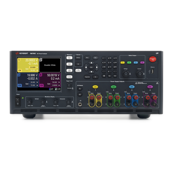
Page 16: Front Panel At A Glance
2. Display - Displays all instrument functions - information changes based on selected function. 3. Measure keys - Selects the measurement function - Meter View, Scope View, or Data Logger. Run- /Stop key starts or stops the scope or data log measurement. Keysight N6705C Operating and Service Guide... - Page 17 Vertical knobs control the vertical size and position. Press Offset to set marker 1. Horizontal knobs control the horizontal size and position. Press Offset to set marker 2. The Trigger knob moves the trigger level up or down. Press this knob to autoscale. Keysight N6705C Operating and Service Guide...
-
Page 18: Rear Panel At A Glance
N6781A and N6785A power modules. 9. Wiring access ports - Access for sense and output wire connections. Used for output connections on power modules rated >20 A. Also used for Keysight N678xA SMU power modules when extremely precise measurements or output guarding is required. -
Page 19: Meter View
Displays the maximum voltage and current ratings of the output. Also displays the present over-voltage protection setting Protection and whether over-current protection is on or off. 10. Other Displays the actual voltage, current, and status of the other outputs. Outputs Keysight N6705C Operating and Service Guide... -
Page 20: Scope View
Measurement Marker 2 enabled. Adjust using Marker 1 knob. Press knob to reset. 12. Intersect Shows where the measurement markers intersect the waveform. Point 13. Meas- Shows the calculations of the waveform data between Marker 1 and Marker 2. urements Keysight N6705C Operating and Service Guide... -
Page 21: Data Logger View
Measurement Marker 2 enabled. Adjust using Marker 1 knob. Press knob to reset. 10. Intersect Shows where the measurement markers intersect the waveform. Point 11. Meas- Shows the calculations of the waveform data between Marker 1 and Marker 2. urements Keysight N6705C Operating and Service Guide... -
Page 22: Arbitrary Waveform Preview
8. Time Indicates the time that the longest Arb will run. In this example, all Arbs run the same amount of time. 9. Close Closes the Arb Preview and returns to the previous measurement view. Keysight N6705C Operating and Service Guide... -
Page 23: Front Panel Menu Reference
Configures the measurements that appear on the bottom of the display in Marker view. Horizontal Properties... Configures the horizontal offset reference and sample points. Datalogger ► Standard View Displays the data log strip chart view including vertical, horizontal, and progress settings. Keysight N6705C Operating and Service Guide... - Page 24 Accesses the password-protected administrative functions. Calibration ► Accesses the calibration functions: Turn On/Off, Voltage, Current, Miscellaneous, Date, Save, Count. Sanitize... Performs NISPOM secure erase of all user data. Firmware Update... Restricts unauthorized access by the Firmware Update Utility. Keysight N6705C Operating and Service Guide...
- Page 25 How to use the front panel controls. Front Panel Navigation... How to navigate the front panel display. Module Capabilities and Ratings How to obtain module capabilities/ratings. About Identifies the mainframe and the installed modules. Keysight N6705C Operating and Service Guide...
-
Page 26: Command Quick Reference
Calibrates the voltage measurement. :AUXiliary, (@channel) Calibrates the auxiliary voltage measurement. (only on N6781A, N6785A) DISPlay [:WINDow] [:STATe] 0|OFF|1|ON Turns the front panel display on or off. :VIEW METER1 | METER4 Selects 1-channel or 4-channel meter view. Keysight N6705C Operating and Service Guide... - Page 27 Returns the peak-to-peak voltage between markers :WHOur? (@chanlist) Returns the watt-hours between markers. :ELOG? <value (@chanlist) Returns the most recent external datalog records. :HISTogram :CURRent 8 | 0.0039, (@chanlist) Returns the cumulative histogram current data (only on N6781A/82A/85A/86A) Keysight N6705C Operating and Service Guide...
- Page 28 Initiates the transient trigger system. :CONTinuous :TRANsient 0|OFF|1|ON, (@chanlist) Continuously initiates the transient trigger system. :IDENtify [:STATe] 0|OFF|1|ON Turns the front panel LXI identify indicator on or off. :MDNS [:STATe] 0|OFF|1|ON Controls the state of the mDNS server. Keysight N6705C Operating and Service Guide...
- Page 29 Enables or disables the output. :COUPle :CHANnel [<value>, {<value>}] Selects which channels are coupled. :DOFFset <value> Sets a delay offset to synchronize coupled output state changes. :MODE AUTO|MANual Specifies the output delay offset coupling mode. Keysight N6705C Operating and Service Guide...
- Page 30 Selects the internal data log current measurement range. :AUTO 0|OFF|1|ON, (@chanlist) Enables/disables seamless measurement autoranging. (only on N6781A/82A/85A/86A) :FUNCtion :CURRent 0|OFF|1|ON, (@chanlist) Enables/disables current data logging. :MINMax 0|OFF|1|ON Enables/disables min/max internal data logging. :VOLTage 0|OFF|1|ON, (@chanlist) Enables/disables voltage data logging. Keysight N6705C Operating and Service Guide...
- Page 31 :OFFSet? 8|0.0039, (@chanlist) Queries the weight of the histogram in amperes :RANGes? (@chanlist) Queries the values of the bin ranges :RANge [:UPPer] <value>, (@chanlist) Selects the internal data log voltage measurement range. :AUTO 0|OFF|1|ON, (@chanlist) Enables/disables seamless Elog measurement autoranging. :FUNCtion Keysight N6705C Operating and Service Guide...
- Page 32 Sets the initial level of the pulse :TIMe <value>, (@chanlist) Sets the length of the start time or delay :TOP [:LEVel] <value>, (@chanlist) Sets the top level of the pulse :TIMe <value>, (@chanlist) Sets the length of the pulse :RAMP Keysight N6705C Operating and Service Guide...
- Page 33 :POINts? (@chanlist) Returns the number of BOST points :DWELl <value>, {<value>}, (@chanlist) Sets the user-defined dwell values :POINts? (@chanlist) Returns the number of dwell points :LEVel <value>, {<value>}, (@chanlist) Sets the user-defined level values Keysight N6705C Operating and Service Guide...
- Page 34 [:TIME] <value>, (@chanlist) Sets the over-current protection delay. :STARt SCHange|CCTRans, (@chanlist) Specifies what starts the over-current protection delay timer. :STATe 0|OFF|1|ON, (@chanlist) Enables/disables the over-current protection. :RANGe <value>, (@chanlist) Sets the output current range. Keysight N6705C Operating and Service Guide...
- Page 35 Returns the number of list points (same as steps). :EOSTep [:DATA] <Bool>{,<Bool>}, (@chanlist) Generates a trigger out at the End Of STep :POINts? (@chanlist) Returns the number of list points (same as steps). :VOLTage Keysight N6705C Operating and Service Guide...
- Page 36 Sets the over-voltage protection level. :DELay [:TIME] <value>, (@chanlist) Sets the over-voltage protection delay. (only on N6783A) :REMote [:POSitive] [:LEVel] <value>, (@chanlist) Sets the positive remote OV protection level. (only on N678xA SMU) :NEGative Keysight N6705C Operating and Service Guide...
- Page 37 :DEFine (@chanlist) Group multiple channels to create a single channel. :DELete (@channel) Remove the specified channel from the group. :ALL Ungroups all channels. :PASSword :FPANel :RESet Resets the front panel lockout password to zero. :PERSona Keysight N6705C Operating and Service Guide...
- Page 38 :SLOPe POSitive|NEGative, (@chanlist) Sets the voltage trigger slope of the data logger. :ELOG [:IMMediate] (@chanlist) Triggers the external data logger immediately. :SOURce <source>, (@chanlist) Selects the trigger source for external data logging: BUS |EXTernal |IMMediate| PIN<1-7> :HISTogram (HISTogram commands only apply to models N6781A/82A/85A/86A) Keysight N6705C Operating and Service Guide...
- Page 39 Selects the trigger source for current histogram: BUS |EXTernal |IMMediate| PIN<1-7> :TRANsient [:IMMediate] (@chanlist) Triggers the output immediately. :SOURce <source>, (@chanlist) Selects the trigger source for the transient system: BUS |EXTernal IMMediate |PIN<1-7> |TRANsient<1-4> Keysight N6705C Operating and Service Guide...
-
Page 40: Model Descriptions, Differences, And Options
300 W / 500 W Precision DC Power Module N6781A, N6782A, N6784A 20 W Source/Measure Unit (SMU) N6785A, N6786A 80 W Source/Measure Unit (SMU) N6783A-BAT / N6783A-MFG 18 W / 24 W Application-Specific DC Power Module Keysight N6705C Operating and Service Guide... - Page 41 Note 2 Option 2UA.is only available on Models N6761A and N6762A. It includes Option 761. Note 3 Option 055 deletes the Data Logger function on Model N6705C. Note 4 Only available when using the remote interfaces; not from the front panel.
- Page 42 Note 1 Arbitrary waveforms and List capability are not available on the negative current output on Model N6783A. Note 2 Option 055 deletes the Data Logger function on Model N6705. Note 3 Only available when using the remote interfaces; not the front panel. Keysight N6705C Operating and Service Guide...
- Page 43 Large gate array. Required on Models N6751A, N6752A Commercial calibration with test results data ISO 17025 calibration certificate 200 microampere measurement range. Only on Models N6761A, N6762A. Note 1 A small AC network is always present across the output terminals. Keysight N6705C Operating and Service Guide...
-
Page 44: Specifications
Supplemental Characteristics Dimension Diagrams This section lists the supplemental characteristics of the Keysight N6705C DC Power Analyzer. Supplemental characteristics are not warranted but are descriptions of performance determined either by design or by type testing. All supplemental characteristics are typical unless otherwise noted. - Page 45 Interface Capabilities LXI Core 2011: 10/100/1000 Base-T Ethernet (Sockets, VXI-11 protocol, Web interface) USB 2.0 (USB-TMC488): Requires Keysight IO Library version M.01.01 or 14.0 and up 10/100/1000 LAN: Requires Keysight IO Library version L.01.01 or 14.0 and up Built-in Web server: Requires a Web browser GPIB:...
-
Page 46: Dimension Diagrams
Note 1: Under full load at 400 Hz, power factor drops from 0.99 @ 120 VAC to as low as 0.76 @ 265 VAC. Power factor degrades further under no load conditions. Dimension Diagrams Keysight N6705C Operating and Service Guide... -
Page 47: Installation
Keysight N6705C Operating and Service Guide Installation Preliminary Information Installing the Power Analyzer Connecting the Power Cord Connecting the Outputs Remote Sense Connections Parallel and Series Connections BNC Connections Auxiliary Measurement Connections Interface Connections... -
Page 48: Preliminary Information
Observe Environmental Conditions Check for Items Supplied Before getting started, check the following list and verify that you have received these items with your unit. If anything is missing, please contact your nearest Keysight Sales and Support Office. Mainframe Items Description... -
Page 49: Inspect The Unit
Review Safety Information This Keysight N6705C DC Power Analyzer is a Safety Class 1 instrument, which means it has a protective earth terminal. That terminal must be connected to earth ground through a power source equipped with a ground receptacle. -
Page 50: Installing The Power Analyzer
Align the power module over the pins and gently push it down onto the connector. Install the screws at each end of the power module. The torque specification for the screws is 9 inch-pounds. Keysight N6705C Operating and Service Guide... - Page 51 Tighten all connector screws. Install the connector in the module. For power modules that use 50 A output connectors – see High Current Output Connections. 1. To front panel binding post 2. 20 A connector Keysight N6705C Operating and Service Guide...
-
Page 52: High-Current Output Connections
2 Installation For Keysight N678xA SMU power modules – Remove the 12A connector plug from the wire harness and install the 8-pin connector plug provided with the power module. Install the front panel cable wires in the output connector as shown. Observe the output color code. Tighten all connector screws. -
Page 53: Bench Installation
Power analyzer mainframes can be mounted in a 19-inch EIA rack cabinet. They are designed to fit in four rack-units (4U) of space. Remove the feet before rack mounting the unit. Do not block the air intake and exhausts at the sides and rear of the unit. Keysight N6705C Operating and Service Guide... -
Page 54: Redundant Ground For 400 Hz Operation
Refer to BNC Connectors later in this section for installation instructions. Refer to the Specifications section for power factor statistics at 400 Hz operation. Keysight N6705C Operating and Service Guide... -
Page 55: Connecting The Power Cord
Connect the power cord to the IEC 320 connector on the rear of the unit. If the wrong power cord was shipped with your unit, contact your nearest Keysight Sales and Support Office. The AC input on the back of your unit is a universal AC input. It accepts nominal line voltages in the range of 100 VAC to 240 VAC. -
Page 56: Connecting The Outputs
Keysight Model N678xA SMU wiring is described in the following section. Along with conductor temperature, you must also consider voltage drop when selecting wire sizes. - Page 57 4. “x” indicates wire is not rated for the maximum output current of the power module. 5. Because of wire inductance considerations, it is also recommended that you keep your load leads twisted, tie wrapped, or bundled together and less than 50 feet (14.7 meters) in length per lead. Keysight N6705C Operating and Service Guide...
-
Page 58: Keysight N678Xa Smu Wiring
2 to 10 meters (inductance per cable foot ≤ 32 nH) High Bandwidth Modes with Remote Sensing The following wiring requirements apply when using Keysight Models N678xA SMU in the High bandwidth modes with remote sensing. Refer to Output Bandwidth for more information about the bandwidth settings. - Page 59 These access ports can also be used when extremely precise output measurements are required. As shown in the following figure, cable guards are available at the internal connector of Keysight Models N678xA SMU. The guard is typically used to drive the shields of cables and test fixtures. It provides a buffered voltage that is at the same potential as the + output terminals of the module connector.
-
Page 60: Multiple Load Wiring
+ and - load wires from the power analyzer to the load. Keep the load leads under 14.7 meters (50 feet) per lead because of inductance effects Note that Keysight Models N678xA SMU have additional wiring restrictions as previously discussed under Keysight N678xA SMU Wiring. -
Page 61: Positive And Negative Voltages
The instrument can be operated with any output terminal ± 240 VDC including output voltage from ground. Keysight Models N678xA SMU are optimized for grounding the negative output terminal. Grounding the positive terminal may result in increased current measurement noise and a reduction in current measurement accuracy. -
Page 62: 4-Wire Sense Connections
Connect the load to the output terminals using separate connecting wires. Keep the wire-pair as short as possible and twist or bundle it to reduce lead inductance and noise pickup. Keep the load leads under 14.7 meters (50 feet) per lead because of inductance effects. Keysight N6705C Operating and Service Guide... -
Page 63: Open Sense Leads
OVP for Keysight N678xA SMU (local OVP) For Keysight Models N678xA SMU only, the OVP circuit senses at the 4-wire sense terminals rather than at the output terminals. This allows for more precise overvoltage monitoring directly at the load. -
Page 64: Output Noise Considerations
The noise specifications documented in the Keysight N6700 DC Power Analyzer Family Specifications Guide apply at the output terminals when using local sensing. However, voltage transients may be produced at the load by noise induced in the leads or by load current transients acting on the inductance and resistance of the load lead. -
Page 65: Parallel And Series Connections
Series Connections Parallel Connections Equipment Damage Only connect power supplies that have identical voltage and current ratings in parallel. Keysight Models N678xA SMU may be paralleled, but ONLY when operated in Current Priority mode. Voltage Priority operation is not allowed. -
Page 66: Series Connections
240 VDC from chassis ground. Only connect outputs that have identical voltage and current ratings in series. Keysight Models N678xA SMU and N6783A–x cannot be connected in series. To prevent currents from damaging the power analyzer when the load is connected, always turn series-connected outputs on and off together. - Page 67 CC load cross regulation, CC source effect, and CC short term drift. These are twice the current programming accuracy (including the percentage portion) at all operating points. Load Transient Recovery Time: Load transient specifications are typically twice the single output. Keysight N6705C Operating and Service Guide...
-
Page 68: Bnc Connections
Step 1. Use the nut driver and remove the hex nut (1) from only one of the BNC connectors. Do not remove the lock washer located behind the hex nut. Step 2. Crimp the ring terminal (2) onto the end of the ground wire Keysight N6705C Operating and Service Guide... - Page 69 Step 4. Tighten the hex nut onto the ring terminal. Step 5. Attach the other end of the redundant ground wire to a convenient earth ground point. Keysight N6705C Operating and Service Guide...
-
Page 70: Auxiliary Measurement Connections
This information only applies when Models N6781A and N6785A are installed in the mainframe. The auxiliary voltage measurement inputs are located on the rear panel of the Keysight N6705C. These are primarily used for battery voltage rundown measurements, but are also suitable for general purpose DC measurements. -
Page 71: Interface Connections
GPIB card. 2. Connect your instrument to the GPIB interface card using a GPIB interface cable. 3. Use the Connection Expert utility of the Keysight IO Libraries Suite to configure the GPIB card’s parameters. 4. The power analyzer is shipped with its GPIB address set to 5. Use the front panel menu if you need to change the GPIB address. -
Page 72: Usb Connections
1. Connect your instrument to the USB port on your computer using a USB cable. 2. With the Connection Expert utility of the Keysight IO Libraries Suite running, the computer will automatically recognize the instrument. This may take several seconds. When the instrument is recognized, your computer will display the VISA alias, IDN string, and VISA address. - Page 73 2 Installation 2. Use the Connection Expert utility of the Keysight IO Libraries Suite to add the power analyzer and verify a connection. To add the instrument, you can request the Connection Expert to discover the instrument. If the instrument cannot be found, add the instrument using its hostname or IP address.
-
Page 74: Digital Port Connections
2 Installation 3. Use the Connection Expert utility of the Keysight IO Libraries Suite to add the power analyzer and verify a connection. To add the instrument, you can request the Connection Expert to discover the instrument. If the instrument cannot be found, add the instrument using its hostname or IP address. - Page 75 When Positive polarity is selected, a logical true signal is a voltage high at the pin. When Negative polarity is selected, a logical true signal is a voltage low at the pin. For more information on configuring the digital port functions, refer to Using the Digital Control Port. Keysight N6705C Operating and Service Guide...
-
Page 77: Using The Source Functions
Generating Arbitrary Waveforms Arb Parameter Reference Using the Protection Functions This section contains instructions on how to operate your Keysight N6705C DC Power Analyzer. The specific functions described in this section are listed above. Equivalent SCPI commands to program a specific function are included at the end of each topic. -
Page 78: Turning The Unit On
To display the error log, press the Menu key, scroll and select Utilities, then Error Log. Errors are stored in the order they are received. The error at the end of the list is the most recent error. Keysight N6705C Operating and Service Guide... -
Page 79: View Instrument Identification
SYST:CHAN:OPT?(@1) SYST:CHAN:SER?(@1) You have the ability to change the identity of the mainframe. This functionality is only intended for compatibility with previous "A" and "B" version mainframes. To change the identity refer to *IDN Setup. Keysight N6705C Operating and Service Guide... -
Page 80: Using The Power Supply
Push the voltage and current knobs to access a pop-up dialog that lets you: 1. Lock/Unlock the knobs. 2. Select limit parameters or select limit tracking on Keysight N678xA SMU and N6783A. You can also enter the voltage and current values directly in the numeric entry fields (the Set fields) in the Meter-view display. - Page 81 @ symbol and be enclosed in parentheses (). To set only output 1 to 10.02 V and 1 A: VOLT 10.02,(@1) CURR 1,(@1) To set the output current limit to 1 A for Keysight Models N678xA SMU and N6783A: Keysight N6705C Operating and Service Guide...
-
Page 82: Configuring An Output Turn-On/Turn-Off Sequence
Press the Settings key twice to access the Output On/Off Delays window. Enter the On Delays and Off Delays for all outputs that will participate in the output on/off delay sequence. Values can range from 0 to 1023 seconds. Keysight N6705C Operating and Service Guide... - Page 83 Step 3, the delay offset may be different based on the outputs that you will actually be sequencing. The minimum turn-on delays of the power modules are documented in the Keysight N6700 DC Power Analyzer Family Specifications Guide. Step 3 – Coupling selected outputs:...
- Page 84 OUTP:COUP:DOFF:MODE MAN OUTP:COUP:DOFF 0.050 To query the delay offset of the slowest power module in the mainframe (the maximum delay offset) in seconds: OUTP:COUP:MAX:DOFF? To turn on two coupled outputs in a sequence: OUTP ON,(@1:2) Keysight N6705C Operating and Service Guide...
-
Page 85: Additional And Advanced Source Settings
Use the navigation keys to select the desired output range. Turn-on Pref - The turn-on preference function only applies to Keysight Models N6761A, N6762A. This specifies the preferred mode for output on/off transitions. It allows output state transitions to be optimized for either constant voltage or constant current operation. - Page 86 To program a voltage slew rate, enter the rate (V/s) in the Voltage Slew field. Check Maximum to program the fastest rate. For Keysight Models N678xA SMU, the voltage slew control is only available in Voltage priority mode. Note that the maximum slew rate is limited by the analog performance of the output circuit.
- Page 87 To set the power limit of outputs 1 and 2 to their maximum settings: POW:LIM MAX,(@1,2) To set the output voltage bandwidth of output 1 to the default setting: VOLT:BWID LOW,(@1) To set the output turn-off mode to the high impedance setting: OUTP:TMOD HIGHZ,(@1) Keysight N6705C Operating and Service Guide...
-
Page 88: N678Xa Smu Source Functions
The Source Settings window lets you access the specialized operating modes of the Keysight N678xA SMU modules when these power modules are installed. The Emulating dropdown list lets you access the specialized operating modes of the Keysight N678xA SMU. Use the navigation keys to select one of the emulating modes. - Page 89 Operation for a detailed description of voltage and current priority. Resistance - This is only available on Keysight Models N6781A and N6785A. Output resistance programming is primarily used in battery emulation applications, and only applies in Voltage Priority mode. Values are programmed in Ohms, from –40 mΩ to +1 Ω.
- Page 90 3 Using the Source Functions Resistance - This is only available on Keysight N6781A and N6785A. Output resistance programming is primarily used in battery emulation applications, and only applies in Voltage Priority mode. Values are programmed in Ohms, from – 40 mΩ to + 1 Ω.
- Page 91 To set the positive current limit of output 1 to 1 A: CURR:LIM 1,(@1) To set the negative current limit, you must first turn limit coupling (tracking) off. Then set the negative current limit to 0.5 A: CURR:LIM:COUP OFF,(@1) CURR:LIM:NEG 0.5,(@1) Keysight N6705C Operating and Service Guide...
-
Page 92: Generating Arbitrary Waveforms
The maximum bandwidth is based on the type of power module that is installed. This is documented in the Keysight N6700 DC Power Analyzer Family Specifications Guide. The arbitrary waveform generator has a variable dwell period, where each point in the waveform is defined by the voltage or current setting along with the dwell time or duration to stay at that setting. -
Page 93: Configuring Pulse Arbs
Specify if the Arb should repeat, either continuously or only for a specified repeat count. A repeat count of 1 runs the Arb once. Select Edit Points to convert the parameters to a User-defined Arb. Keysight N6705C Operating and Service Guide... - Page 94 ARB:VOLT:PULS:STAR 0, (@1) ARB:VOLT:PULS:TOP 10, (@1) ARB:VOLT:PULS:STAR:TIM .25,(@1 ARB:VOLT:PULS:TOP:TIM .5,(@1) ARB:VOLT:PULS:END:TIM .25,(@1) ARB:TERM:LAST OFF,(@1) To set up the transient trigger system and trigger the Arb: VOLT:MODE ARB,(@1) TRIG:ARB:SOUR BUS OUTP ON,(@1) INIT:TRAN (@1) *TRG Keysight N6705C Operating and Service Guide...
-
Page 95: Configuring User-Defined Arbs
Specify what happens when the waveform completes – select whether the output returns to the DC value that was in effect before the waveform started, or whether the output should remain at the last Arb value. Keysight N6705C Operating and Service Guide... - Page 96 BNC Trigger In selects the rear trigger input BNC connector as the trigger source. Remote command selects a remote interface command as the trigger source. Keysight N6705C Operating and Service Guide...
-
Page 97: Configuring Constant-Dwell Arbs
CD Arb. Also, the minimum dwell time of a CD Arb is 10 .24 microseconds, instead of the 1 microsecond resolution of the other Arbs. Keysight N6705C Operating and Service Guide... - Page 98 Arb value. Specify if the Arb should repeat, either continuously or only for a specified repeat count. A repeat count of 1 runs the Arb once. Keysight N6705C Operating and Service Guide...
- Page 99 Arb will be triggered as soon as you run it. BNC Trigger In selects the rear trigger input BNC connector as the trigger source. Remote command selects a remote interface command as the trigger source. Keysight N6705C Operating and Service Guide...
- Page 100 Refer to Measurement Data Formats for more information. To set up the transient trigger system and trigger the CD Arb: VOLT:MODE ARB,(@1) TRIG:ARB:SOUR BUS OUTP ON,(@1) INIT:TRAN (@1) *TRG Keysight N6705C Operating and Service Guide...
-
Page 101: Configuring An Arb Sequence
For step 0, select an Arb type from the Name dropdown list. Select the Edit button or Properties key to edit the waveform. The example below shows the Pulse waveform type. Refer to Configuring Pulse Arbs for information on setting the Pulse parameters. Keysight N6705C Operating and Service Guide... - Page 102 Last Arb Value. Also specify if the Arb sequence should repeat, either continuously or only for a specified repeat count. A repeat count of 2 runs the sequence twice. Keysight N6705C Operating and Service Guide...
- Page 103 Remote command selects a remote interface command as the trigger source. Step 5 – Preview and run the Arb: The Arb Preview dialog shown above provides a preview of the Constant-dwell waveform that will be run on output 1. Keysight N6705C Operating and Service Guide...
- Page 104 To program step 2 as a voltage sine wave: ARB:SEQ:STEP:FUNC:SHAP SIN,2,(@1) ARB:SEQ:STEP:VOLT:SIN:FREQ 0.0167,2,(@1) ARB:SEQ:STEP:VOLT:SIN:OFFS 10.0,2,(@1) ARB:SEQ:STEP:VOLT:SIN:AMPL 20.0,2,(@1) To repeat step 0 twice: ARB:SEQ:STEP:COUN 2,0,(@1) To set the pacing for step 2 to triggered: ARB:SEQ:STEP:PAC TRIG,2,(@1) Keysight N6705C Operating and Service Guide...
-
Page 105: Arb Trigger Sources
Arb Run/Stop Key The front panel Run/Stop key. BNC Trigger In The rear trigger input BNC connector Remote Command A remote interface command. From the remote interface: Select from one of the following SCPI trigger sources: Keysight N6705C Operating and Service Guide... -
Page 106: Arb Triggers
Once configured, the instrument will wait indefinitely for the trigger signal. If the trigger does not occur, and you wish to cancel the arbitrary waveform, press the Arb Run/Stop key to stop the Arb. From the remote interface: To initiate the transient trigger system: INIT:TRAN(@1) Keysight N6705C Operating and Service Guide... -
Page 107: Importing/Exporting Arb Data
You can create an arbitrary waveform in a Microsoft Excel spreadsheet and import it into the instrument using the Import function as previously explained in this section under Configuring User- Defined Properties Configuring Constant-Dwell Properties. Likewise, you can also Export an arbitrary waveform from the instrument to a spreadsheet. Keysight N6705C Operating and Service Guide... - Page 108 TRIGGER column requires a value of zero as the default. If you want the Arb to generate an external trigger signal at the start of the step, replace the zero with a one. For constant-dwell Arbs, the data in the VALUE column must match the Arb type; either voltage or current values. Keysight N6705C Operating and Service Guide...
-
Page 109: Arb Parameter Reference
The maximum repeat count for voltage and current CD Arbs is 256. Close Saves and closes the Properties window. From the remote interface: The parameter setting returns to the DC value that was in effect prior to the Arb. Keysight N6705C Operating and Service Guide... -
Page 110: Constant-Dwell Parameters
The total time of the imported Arb. Repeat Count The maximum repeat count for CD Arbs is 256. From the remote interface: The dwell time for each step in seconds.: ARB:CURR:CDW:DWEL 0.01,(@1) ARB:VOLT:CDW:DWEL 0.01,(@1) Keysight N6705C Operating and Service Guide... -
Page 111: Exponential Parameters
The delay after the trigger is received but before the waveform starts: ARB:CURR:EXP:STAR:TIM 0.25,(@1) ARB:VOLT:EXP:STAR:TIM 0.25,(@1) Time for the amplitude to go from the start setting to the end setting: ARB:CURR:EXP:TIM 0.75,(@1) ARB:VOLT:EXP:TIM 0.75,(@1) The time constant of the curve: Keysight N6705C Operating and Service Guide... -
Page 112: Pulse Parameters
The delay after the trigger is received but before the pulse starts: ARB:CURR:PULS:STAR:TIM 0.25,(@1) ARB:VOLT:PULS:STAR:TIM 0.25,(@1) The width of the pulse: ARB:CURR:PULS:TOP:TIM 0.5,(@1) ARB:VOLT:PULS:TOP:TIM 0.5,(@1) The time the output remains at the end setting after the pulse: ARB:CURR:PULS:END:TIM 0.25,(@1) ARB:VOLT:PULS:END:TIM 0.25,(@1) Keysight N6705C Operating and Service Guide... -
Page 113: Ramp Parameters
The delay after the trigger is received but before the ramp starts: ARB:CURR:RAMP:STAR:TIM 0.25,(@1) ARB:VOLT:RAMP:STAR:TIM 0.25,(@1) The time that the output ramps up: ARB:CURR:RAMP:RTIM 0.5,(@1) ARB:VOLT:RAMP:RTIM 0.5,(@1) The time the output remains at the end setting after the ramp: ARB:CURR:RAMP:END:TIM 0.01,(@1) ARB:VOLT:RAMP:END:TIM 0.01,(@1) Keysight N6705C Operating and Service Guide... -
Page 114: Sine Parameters
The frequency of the sine wave. From the remote interface: The amplitude or peak value: ARB:CURR:SIN:AMPL 1,(@1) ARB:VOLT:SIN:AMPL 5,(@1) The offset from zero: ARB:CURR:SIN:OFFS 1,(@1) ARB:VOLT:SIN:OFFS 5,(@1) The frequency of the sine wave: ARB:CURR:SIN:FREQ 1,(@1) ARB:VOLT:SIN:FREQ 1,(@1) Staircase Parameters Keysight N6705C Operating and Service Guide... - Page 115 The time to complete all staircase steps: ARB:CURR:TIM 0.2,(@1) ARB:VOLT:TIM 0.2,(@1) The time the output remains at the end setting after the staircase: ARB:CURR:STA:END:TIM 0.2,(@1) ARB:VOLT:STA:END:TIM 0.2,(@1) The total number of staircase steps: ARB:CURR:STA:NST 3,(@1) ARB:VOLT:STA:NST 3,(@1) Keysight N6705C Operating and Service Guide...
-
Page 116: Step Parameters
The setting before the step: ARB:CURR:STEP:STAR 0,(@1) ARB:VOLT:STEP:STAR 0,(@1) The setting after the step: ARB:CURR:STEP:END 1,(@1) ARB:VOLT:STEP:END 5,(@1) The delay after the trigger is received before the step occurs: ARB:CURR:STEP:STAR:TIM 0.01,(@1) ARB:VOLT:STEP:STAR:TIM 0.01,(@1) Trapezoid Parameters Keysight N6705C Operating and Service Guide... - Page 117 The time that the trapezoid ramps up (RTIM) and down (FTIM): ARB:CURR:TRAP:RTIM 0.5,(@1) ARB:VOLT:TRAP:RTIM 0.5,(@1) ARB:CURR:TRAP:FTIM 0.5,(@1) ARB:VOLT:TRAP:FTIM 0.5,(@1) The width of the peak: ARB:CURR:TRAP:TOP:TIM 1.5,(@1) ARB:VOLT:TRAP:TOP:TIM 1.5,(@1) The time the output remains at the end setting after the trapezoid: ARB:CURR:TRAP:END:TIM 0.25,(@1) ARB:VOLT:TRAP:END:TIM 0.25,(@1) Keysight N6705C Operating and Service Guide...
-
Page 118: User-Defined Parameters
The time that the output stays at the steps: ARB:CURR:UDEF:DWEL 1,2,3,2,1,(@1) ARB:VOLT:UDEF:DWEL 1,2,3,2,1,(@1) Generate an external trigger signal at the start of the step (the trigger is generated at the start of step #3): ARB:CURR:UDEF:BOST 0,0,1,0,0,(@1) ARB:VOLT:UDEF:BOST 0,0,1,0,0,(@1) Keysight N6705C Operating and Service Guide... -
Page 119: Arb Sequence Parameters
The more of these waveforms that are added to the sequence, the fewer points will be allocated, down to a minimum of 16 points. Advanced Lets you edit the common properties that apply to the entire sequence. See Common Properties for more information. Keysight N6705C Operating and Service Guide... - Page 120 ARB:SEQ:STEP:FUNC:SHAP PULS,0,(@1) ARB:SEQ:STEP:VOLT:PULS:STAR:TIM 0.25,0,(@1) ARB:SEQ:STEP:VOLT:PULS:TOP 10.0,0,(@1) ARB:SEQ:STEP:VOLT:PULS:TOP:TIM 0.5,0,(@1) ARB:SEQ:STEP:VOLT:PULS:END:TIM 0.25,0,(@1) The time of step 0 is the sum of the Start Time, Top Time and End Time. The default pacing for sequence steps is Dwell-pacing. Keysight N6705C Operating and Service Guide...
-
Page 121: Using The Protection Functions
INH - The Inhibit input (pin 3) on the rear panel digital connector can be programmed to act as an external shutdown signal. Refer to Inhibit Input for further information. Keysight N6705C Operating and Service Guide... -
Page 122: Configuring Protection
Enable Output Coupling – Checking this box lets you couple the outputs so that when a protection fault occurs on one output, ALL outputs will be turned off. Keysight N6705C Operating and Service Guide... -
Page 123: Advanced Protection
OUTP:PROT:COUP ON To clear an output protection fault on output 1: OUTP:PROT:CLE (@1) Advanced Protection Press the Settings key to access the Source Settings window. Navigate to and select Protection. Navigate to and select Advanced. Keysight N6705C Operating and Service Guide... - Page 124 1 to 3600 seconds in 1 second increments. Enable Oscillation Protection - This is only available on Keysight Models N678xA SMU. If open sense leads or capacitive loads outside the allowable range cause the output to oscillate, the oscillation protection function detects the oscillation and latches the output off.
-
Page 125: Using The Measurement Functions
Keysight N6705C Operating and Service Guide Using the Measurement Functions Using the Meter Functions Using the Scope Functions Using the Data Logger Functions External Data Logging Equivalent SCPI commands to program a specific function are included at the end of each topic. However some functions such as the front panel Scope... -
Page 126: Using The Meter Functions
The accuracy of the voltage and current measurements is based on the type of power modules that are installed, as documented in Keysight N6700 DC Power Analyzer Family Specifications Guide Meter View Each output has its own measurement capability. -
Page 127: Meter Ranges And Measurement Times
NPLC - Specify the number of power line cycles (NPLC) that the measurement will span. Increase the NPLC for improved accuracy and noise reduction on low current and voltage measurements. Duration – Indicates the duration of the measurement based on the Frequency and NPLC settings. Keysight N6705C Operating and Service Guide... -
Page 128: Seamless Measurements
Front Panel Preferences dialog, located in the Utilities menu. To enable seamless voltage or current autoranging, press the Meter View key, then press Properties. In the Voltage or Current dropdown menu, select Auto. Keysight N6705C Operating and Service Guide... -
Page 129: N678Xa Smu Meter-Only Modes
The input impedance in Voltage Measure mode will be somewhere around 2000 pF depending on the grounding of the DUT. This may draw up to a few microamperes of current from the nodes that are being measured. Keysight N6705C Operating and Service Guide... - Page 130 High3 setting with a compensation capacitor across the DUT. Capacitors can be film or ceramic with values from 7 µF to 150 µF. Refer to Keysight N678xA SMU Wiring for additional wiring information. Keysight N6705C Operating and Service Guide...
-
Page 131: Auxiliary Voltage Measurements
+ and − sense terminals. These functions include the front panel, SCPI measurements, Scope View, Data Logger View, Elog, and histogram measurements. From the front panel: To enable auxiliary voltage measurements, select Meter View, then Properties, then select Aux Voltage. Keysight N6705C Operating and Service Guide... - Page 132 1.6V. This is a normal indication which does not affect the external voltage measurement once the measurement terminals are connected. From the remote interface: To specify the auxiliary voltage measurement input: SENS:FUNC:VOLT:INP AUX,(@1) Keysight N6705C Operating and Service Guide...
-
Page 133: Using The Scope Functions
You can configure the Scope View to display voltage or current waveforms for all outputs. Power waveforms can only be displayed on Keysight Models N676xA and N678xA SMU, as these have simultaneous voltage and current measurement capability (see Model Differences). - Page 134 Press the Properties key to configure the scope properties as follows: In the Trigger Source dropdown list, select Output On/Off Key. In the Mode dropdown list, select Single. Select the Horizontal button and make sure that the Horizontal Offset Reference is set to Left. Keysight N6705C Operating and Service Guide...
-
Page 135: Scope View
You cannot program the scope from the remote interface. Scope View Press the Scope View key to view the scope. This key toggles between the Standard view shown below, and Marker view, which enables markers and marker calculations. Keysight N6705C Operating and Service Guide... - Page 136 6 Ground Reference The ground reference of the trace. Ground references are offset so that they do not overlap. The ground reference offset value is referenced to the horizontal center line of the grid. Keysight N6705C Operating and Service Guide...
- Page 137 20 ms/division, the scope will sample at its fastest rate, depending on the number of traces selected: 1 trace (Model N678xA SMU only): 5.12 microseconds 1 to 2 traces (all modules): 10.24 microseconds 3 to 4 traces (all modules): 20.48 microseconds Keysight N6705C Operating and Service Guide...
- Page 138 Calculates the rms value between the marker locations. To view the rms values, you may need to unselect one of the other measurements in the Scope Marker Properties window. Only 5 measurements may be displayed at a time. Keysight N6705C Operating and Service Guide...
- Page 139 Applies to ALL traces. 5 Horizontal Offset Moves the waveform to the right or left of the horizontal offset reference. The trigger point is indicated by the solid arrow. Keysight N6705C Operating and Service Guide...
-
Page 140: Scope Properties
Source dropdown lets you select a trigger source. This trigger source will trigger the scope measurements on all output channels. Depending upon the selected trigger source, you can trigger the scope as follows: Keysight N6705C Operating and Service Guide... -
Page 141: Scope Ranges
Scope range settings are independent of the Meter View and Data Logger range settings. In the Scope Ranges area, select the desired lower measurement range from the Voltage or Current dropdown menus. Keysight N6705C Operating and Service Guide... -
Page 142: Scope Markers
Marker view. Measurements apply to the portion of the waveform between the two markers. You can only select a maximum of five measurements to be displayed. Horizontal Properties Select the Horizontal button to configure the horizontal properties. Keysight N6705C Operating and Service Guide... -
Page 143: Scope Presets
Select the Preset button to return the Scope View to the power-on display settings. The vertical offset of each trace will be set to a different value. This is to prevent the traces from overlapping. The offset is referenced to the horizontal center line of the grid. Keysight N6705C Operating and Service Guide... -
Page 144: Using The Data Logger Functions
Program the voltage and time values as follows: Step 0: 10 V; 1 s Step 1: 20 V; 1 s Step 2: 30 V; 1 s Step 3: 40 V; 1 s Step 4: 50 V; 1 s Repeat Count: 5 Keysight N6705C Operating and Service Guide... - Page 145 Press the Properties key to configure the data logger properties. Leave the default Duration and Sample Period at 30 seconds and 100 milliseconds respectively. Select the Trigger button and set the trigger source to Arb Run/Stop Key. Keysight N6705C Operating and Service Guide...
- Page 146 You can also use the Vertical Volts/Div knob and the Horizontal Time/Div knob to zoom in on any por- tion of the logged data. From the remote interface: To program a User-defined voltage waveform of five steps on output 1: Keysight N6705C Operating and Service Guide...
-
Page 147: Data Logger View
FETC:DLOG:VOLT:MIN? (@1) FETC:DLOG:VOLT:MAX? (@1) Data Logger View Press the Data Logger key to access the data logger. This key toggles between the Standard view shown below, and Marker view, which enables markers and marker calculations. Keysight N6705C Operating and Service Guide... - Page 148 Shows the location of the voltage or current trigger level and output. In this example, the voltage trigger level of output 1 is shown. The trigger source and amplitude are shown at the bottom right of the display. Keysight N6705C Operating and Service Guide...
- Page 149 Offset Time. The yellow part of the bar represents the data that is visible on the display. The black part represents the offset time. Marker View Keysight N6705C Operating and Service Guide...
- Page 150 Calculates the Watt-hours between the marker locations. To view the Watt hours, you may need to unselect one of the other measurements in the Datalogger Marker Properties window. Only 5 measurements may be displayed at a time. Using the Waveform Display Knobs Keysight N6705C Operating and Service Guide...
-
Page 151: Data Logger Properties
Jump to peak to move the marker to the peak measurement point of the trace. Data Logger Properties From the front panel: With the Data Logger View displayed, press the Properties key to access the Scope Properties window. Keysight N6705C Operating and Service Guide... - Page 152 You cannot data log output power from the remote interface. To obtain power data, you need to data log both voltage and current and then calculate the power from the resulting voltage and current data. To log the minimum and maximum values to the data log file for all enabled outputs: Keysight N6705C Operating and Service Guide...
-
Page 153: Data Logger Ranges
Auto to enable seamless measurement ranging. Seamless ranging does not include the 10 μA range, which must be selected manually. From the remote interface: To enable seamless measurement autoranging: SENS:DLOG:CURR:RANG:AUTO ON,(@1) SENS:DLOG:VOLT:RANG:AUTO ON,(@1) To select a lower current or voltage measurement range: Keysight N6705C Operating and Service Guide... -
Page 154: Data Logger Trigger
If a trigger source is grayed out, it is unavailable. For example, current levels are not available as trigger sources on outputs that have been grouped (paralleled). Note also that a trace must be turned on for it to be used as a trigger source. Keysight N6705C Operating and Service Guide... - Page 155 TRIG:DLOG:VOLT:SLOP POS,(@3) To select a current trigger level and slope on output 4 for the datalog: TRIG:DLOG:CURR 1,(@4) TRIG:DLOG:CURR:SLOP POS,(@4) To specify a trigger offset at 25 percent of the duration of the datalog: Keysight N6705C Operating and Service Guide...
-
Page 156: Data Logger Filename
Select the Markers button to configure the measurements that appear on the bottom of the display in Marker view. Measurements apply to the portion of the trace between the two markers. You can only Keysight N6705C Operating and Service Guide... -
Page 157: Data Logger Presets
Select the Preset button to return the Data Logger View to the power-on display settings. The vertical offset of each trace will be set to a different value. This is to prevent the traces from overlapping. The offset is referenced to the horizontal center line of the grid. Keysight N6705C Operating and Service Guide... -
Page 158: Data Logger Sampling Modes
24 parameters (average voltage+min+max X 4 outputs, and average current+min+max X 4 outputs) with a corresponding decrease in measurement sample rate. The following typical sample periods are based on the number of parameters selected: Keysight N6705C Operating and Service Guide... - Page 159 Available capabilities for ALL outputs • Sample period: 20.48 microseconds to 60 seconds • Trigger source: all trigger sources available • Trigger offset: 0 to 100% • Values logged: average, minimum, maximum (minimum/maximum values must be selected) Keysight N6705C Operating and Service Guide...
-
Page 160: Data Logger And Scope Display Differences
Left, center, or right Does not apply to strip chart set reference Trace save Press File, select Save. Automatically saved to default.dlog file (A different file name can be specified prior to running the data- log.) Keysight N6705C Operating and Service Guide... -
Page 161: External Data Logging
Can log data at up to 20.48 microseconds for one para- Can log data at up to 102.4 microseconds for one para- meter. meter with data format = real. Programming the external data logger consists of: Keysight N6705C Operating and Service Guide... -
Page 162: Select The Measurement Function And Range
Seamless ranging does not include the 10 μA range, which must be selected manually. To enable seamless elog autoranging on channel 1: SENS:ELOG:VOLT:RANG:AUTO ON,(@1) SENS:ELOG:CURR:RANG:AUTO ON,(@1) Keysight N6705C Operating and Service Guide... -
Page 163: Specify The Integration Period
Selects a specific pin that is configured as a Trigger Input on the digital port. The selected pin must be configured as a Trigger Input in order to be used as a trigger source (see Using the Digital Port). Use the following commands to select a trigger source. To select Bus triggers: Keysight N6705C Operating and Service Guide... -
Page 164: Initiate And Trigger The Elog
Binary data is returned as a comma-separated list of data for each channel requested. The data is a definite length binary block, with the byte order specified by the FORMat:BORDer command. Terminate the Elog ABOR:ELOG, (@1) Keysight N6705C Operating and Service Guide... -
Page 165: Using The System Functions
Keysight N6705C Operating and Service Guide Using the System Functions Using the File Functions Specifying User Preferences Using the Administrative Tools Configuring the Remote Interfaces Most of the system functions can only be programmed using the front panel menus. -
Page 166: Using The File Functions
Press the File key to access the file functions, then scroll to and select from the following: Save Function To save the instrument state, scope data, or an Arb sequence, press the File key, then scroll to and select Save. Keysight N6705C Operating and Service Guide... -
Page 167: Load Function
Internal:\ specifies the instrument’s internal memory. External:\ specifies the Memory port on the front panel. Browse Lets you browse another directory or USB memory device. Save Loads the data from the binary file into the instrument. Keysight N6705C Operating and Service Guide... -
Page 168: Export Function
Lets you browse another directory or USB memory device. Export Exports the data to the file name in .csv format. Import Function To import (and convert) Arb data (user-defined or CD), press the File key, then scroll to and select Import. Keysight N6705C Operating and Service Guide... -
Page 169: Screen Capture
Create .gif Saves the image to the specified .gif file. The time of step 0 is the sum of the Start Time, Top Time and End Time. The default pacing for sequence steps is Dwell-pacing. Keysight N6705C Operating and Service Guide... -
Page 170: File Management
Specifies a file or directory to be deleted. Internal:\ specifies the instrument’s internal memory. External:\ specifies the Memory port on the front panel. Browse Lets you browse another directory or USB memory device. Delete Deletes the selected file. Keysight N6705C Operating and Service Guide... - Page 171 File Management. In the Action dropdown box, select Copy. Parameter Description Path\File Name Specifies the file to be copied. Internal:\ specifies the instrument’s internal memory. External:\ specifies the Memory port on the front panel. Keysight N6705C Operating and Service Guide...
-
Page 172: Reset/Recall/Power-On State
As shipped, the power analyzer is configured to automatically recall the Reset State (*RST) settings at power-on. However, you can configure the reset, recall, and power-on state of the instrument. Press the File key, then scroll and select Reset/Recall/Power-On State. Keysight N6705C Operating and Service Guide... -
Page 173: Using An External Usb Memory Device
You can export scope data and logged data to a spreadsheet such as Microsoft Excel on your PC as follows: 1. Collect the scope or logged data using the power analyzer. 2. Insert a USB memory device into the Memory port on the front of the power analyzer. Keysight N6705C Operating and Service Guide... - Page 174 Data is saved in binary format. To export in .csv format you must Load the data from the USB memory device back into the instrument and Export the data in .csv format as previously described under “Exporting Data to a Spreadsheet”. Keysight N6705C Operating and Service Guide...
-
Page 175: Specifying User Preferences
Wait - when Screen saver is enabled, enter a value in minutes in this field to specify the time when the screen saver will activate. The wait can be set from 30 to 999 minutes in 1 minute increments. Keysight N6705C Operating and Service Guide... -
Page 176: Front Panel Lockout
When shipped from the factory, the power analyzer’s clock is set to Greenwich mean time. To access the clock function press the Menu key, scroll down and select Utilities, then User Preferences, then Clock Setup. Keysight N6705C Operating and Service Guide... -
Page 177: Idn Setup
The *IDN setup change and PERSona commands affects the following identification items: *IDN? command for vendor and model VISA programmatic access APIs for vendor and model LXI instrument web pages LXI XML LXI mDNS announcements Keysight N6705C Operating and Service Guide... -
Page 178: Using The Administrative Tools
If a password is required, enter it in to the PIN field, select the Login button and press [Enter]. As shipped from the factory, the password is 0 (zero). If the PIN field shows 0; simply select the Login button and press [Enter]. Keysight N6705C Operating and Service Guide... -
Page 179: Calibration
You must use the Firmware Update Utility to update the firmware in your instrument. Refer to Firmware Update for more information. You can restrict access to the instrument by the Firmware Update Utility. This prevents unauthorized users from updating the firmware. Check Login as administrator to allow firmware update. Keysight N6705C Operating and Service Guide... -
Page 180: Install Options
2. Entering your Order and Certificate number (these appear in your Software Entitlement Cer- tificate). 3. Entering the Host instrument's 10-character serial number (this is located on the rear panel of the instrument). 4. Selecting the software license for the instrument. Keysight N6705C Operating and Service Guide... -
Page 181: Change Password
0. If the message “Locked out by internal switch setting” or “Calibration is inhibited by switch setting” appears, the internal switch is set to prevent the password from being changed (refer to the calibration switches section). Keysight N6705C Operating and Service Guide... -
Page 182: Configuring The Remote Interfaces
Using Sockets Using Telnet Securing the LAN This Keysight N6705C DC Power Analyzer supports remote interface communication over three interfaces: GPIB, USB, and LAN. All three interfaces are live at power on. For information on connecting the interfaces, refer to Interface Connections. -
Page 183: Usb Configuration
As shipped from the factory, the power analyzer’s pre-configured settings should work in most LAN environments. If you need to manually configure these settings, press the Menu key, scroll down and select the Utilities, then select I/O Configuration, then LAN Settings. Keysight N6705C Operating and Service Guide... - Page 184 6-character model number (e.g. N6705C), and serialnumber is the last five characters of the 10-character mainframe serial num- ber located on the label on the top of the unit (e.g. 45678 if the serial number is MY12345678).
- Page 185 Non-volatile Settings. You can also perform an LXI LCI reset by selecting LAN Reset. This resets the DHCP, DNS server address configuration, mDNS state, mDNS service name and the web password. These settings are Keysight N6705C Operating and Service Guide...
-
Page 186: Using The Web Interface
4. For additional help about any of the pages, click on the ? icon. If desired, you can control access to the Web interface by enabling or disabling Web control under LAN Services (see Securing the LAN). Keysight N6705C Operating and Service Guide... -
Page 187: Using Sockets
Power supplies allow any combination of up to six simultaneous data socket, control socket, and telnet connections to be made. Keysight instruments have standardized on using port 5025 for SCPI socket services. A data socket on this port can be used to send and receive ASCII/SCPI commands, queries, and query responses. All commands must be terminated with a newline for the message to be parsed. - Page 188 5 Using the System Functions Check or uncheck Enable LAN Services. Under Enable/Disable LAN services, configure the services that you wish to enable. LAN services must be enabled in order to enable the Web interface control. Keysight N6705C Operating and Service Guide...
-
Page 189: Advanced Source, Measurement, And Control
Keysight N6705C Operating and Service Guide Advanced Source, Measurement, and Control Advanced Source Operation Advanced Measurements Using the Digital Control Port This section discusses the difference between constant voltage and constant current operating modes, multiple output quadrant operation, and other advanced source functions. -
Page 190: Advanced Source Operation
N678xA Output Bandwidth Single-Quadrant Operation The Keysight N6705C DC Power Analyzer can operate in either constant voltage (CV) or constant current (CC) over the rated output voltage and current. Constant voltage mode is defined as an operating mode in which the dc source maintains its output voltage at the programmed voltage setting in spite of changes in load, line, or temperature. -
Page 191: Autoranging
Autoranging only applies to Keysight N675xA and N676xA power modules. The following figure illustrates the autoranging output characteristic of the Keysight N675xA and N676xA power modules. Point 3 shows a situation in which the voltage and current settings are such that the operating locus is limited by the maximum output power boundary of the output. -
Page 192: Cc Mode Delay
CC status bit. To determine when the output will shut down, you must add the time it takes to set the CC status bit to the over-current protection delay time. If the over-current persists beyond the sum of these two time intervals, the output will shut down. Keysight N6705C Operating and Service Guide... -
Page 193: Power Limit Operation
For Keysight N678xA SMU and N6783A-BAT/MFG, the power limit function does not apply. For Keysight N675xA, and N676xA power modules, the power limit function limits the output power at its programmed setting. A status bit (CP+) will indicate that the output is in power limit mode. When the power drawn by the load is reduced below the power limit setting, the output returns to normal operation. -
Page 194: Output Grouping
Over-current protection delay has a slightly slower response time (~10 ms) and slightly less res- olution than an ungrouped output. The power limit setting for Keysight N673xB, N674xB, N677xA, and N6783A power modules must be set to its maximum value. -
Page 195: N678Xa Multi-Quadrant Operation
SYST:REB N678xA Multi-Quadrant Operation Keysight Models N678xA SMU can be operated in either voltage or current priority mode. They can source as well as sink output power. Note that Keysight Models N6781A, N6782A, N6785A, and N6786A operate only in the + Voltage quadrants. - Page 196 OV or OV- and the PROT status bits will be set. Either the user-defined over-voltage setting or the local over-voltage function can trip the over- voltage protection. Keysight N6705C Operating and Service Guide...
- Page 197 If the output voltage reaches either the positive or negative voltage limit, the unit no longer operates in constant current mode and the output current is no longer held constant. Instead, the power analyzer will now regulate the output voltage at its voltage limit setting. Either a LIM+ (positive Keysight N6705C Operating and Service Guide...
-
Page 198: N678Xa Output Bandwidth
OC and PROT status bits will be set. N678xA Output Bandwidth Keysight Models N678xA SMU have several voltage bandwidth modes that let you optimize output response time with capacitive loads. The Low bandwidth setting provides stability with a wide range of load capacitors. Additional bandwidth modes provide faster output response when the load capacitance is restricted to smaller ranges. - Page 199 OSC status bit. From the remote interface: The compensation function is set using the following SCPI command: VOLT:BWID <LOW|HIGH1|HIGH2|HIGH3>, (@1) When queried, the returned value is the bandwidth that was selected. Keysight N6705C Operating and Service Guide...
-
Page 200: Advanced Measurements
Select a Measurement Function and Range The following commands select a measurement function. To enable voltage measurements on channels 1-4, use: SENS:FUNC:VOLT ON,(@1:4) To enable voltage measurements on channels 1-4, use: SENS:FUNC:CURR ON,(@2) Keysight N6705C Operating and Service Guide... - Page 201 To select the 1 A current range on channel 1: SENS:CURR:RANG 1,(@1) Seamless Measurements - For Keysight Models N6781A, N6782A, N6785A, and N6786A, you can select seamless measurement autoranging, which enables a wide dynamic measurement range with no data lost when transitioning across ranges. Seamless autoranging does not include the 10 μA range, which must be selected manually.
- Page 202 When the value is 0, all measurement samples are taken after the trigger. Positive values represent the delay after the trigger occurs but before the samples are acquired. This can be used to exclude measurement samples that occur during the delay time. (Delay time = offset x sample period). Keysight N6705C Operating and Service Guide...
- Page 203 VOLTage<1-4> Triggers the measurement when the voltage of the corresponding output passes through the specified level. Use the following commands to select a trigger source. To select Bus triggers for output 1: TRIG:ACQ:SOUR BUS,(@1) Keysight N6705C Operating and Service Guide...
- Page 204 It takes a few milliseconds for the instrument to be ready to receive a trigger signal after receiving the INITiate:ACQuire command, and it can take longer for Keysight Models N678xA SMU. If a trigger occurs before the trigger system is ready for it, the trigger will be ignored. You can test the WTG_meas bit in the operation status register to know when the instrument is ready to receive a trigger after being initiated.
- Page 205 To return the high level of a pulse: FETC:VOLT:HIGH?(@1) FETC:CURR:HIGH?(@1) To return the low level of a pulse: FETC:VOLT:LOW?(@1) FETC:CURR:LOW?(@1) To return the maximum value: FETC:VOLT:MAX?(@1) FETC:CURR:MAX?(@1) To return the minimum value: FETC:VOLT:MIN?(@1) FETC:CURR:MIN?(@1) Keysight N6705C Operating and Service Guide...
-
Page 206: Measurement System Bandwidth
The measurement bandwidth of the power analyzer is dependent on the following factors: Whether voltage or current is being measured. Whether dynamic current correction has been turned on or off. The analog bandwidth of the power module. Keysight N6705C Operating and Service Guide... - Page 207 N6754A, N6756A, N6764A, N6766A 2.2 μF N6733B, N6743B 13.4 μF N6773A 13.2 μF N6734B, N6744B 9.8 μF N6774A 11.2 μF N6735B, N6745B 12.8 μF N6775A 4.02 μF N6736B, N6746B 3.52 μF N6776A, N6777A 3.54 μF Keysight N6705C Operating and Service Guide...
-
Page 208: Averaged Measurements
6 Advanced Source, Measurement, and Control For example, if you are measuring the output current on a Keysight N6731B with a 10 ohm load connected to the output, and with dynamic current correction turned off, the largest frequency that can be measured without introducing measurement errors is 530 Hz. If a 1 ohm load were connected to the output, the largest frequency that could be measured without errors would be 5.3 kHz. - Page 209 3 A current range on channel 1: SENS:HIST:CURR:RANG 3,(@1) Seamless Measurements - For Keysight Models N6781A, N6782A, N6785A, and N6786A, you can select seamless current autoranging, which results in a wide dynamic range with no data lost across ranges. Seamless ranging does not include the 10 μA range, which must be selected manually. To...
- Page 210 Each Fetch returns the latest cumulative histogram data. The measurement continues until it is aborted. The count bins are 64-bits wide, which eliminates any concern for overflow. Terminate the Measurement Measurements continue until the histogram is aborted. To abort the histogram measurement: ABOR:HIST (@1) Keysight N6705C Operating and Service Guide...
-
Page 211: Measurement Data Formats
Real - Data is returned in binary IEEE single precision floating point. In this case the four bytes of each value can be returned in either big-endian or little-endian byte order, determined by the FORMat:BORDer setting. The following command specifies the data format: FORM ASCII | REAL Keysight N6705C Operating and Service Guide... -
Page 212: Dynamic Current Measurement Control
When the output current is measured and averaged over a number of samples as in the case of static measurements, the inaccuracy is insignificant. However, with the power analyzer’s scope and data logging functions, which capture thousands of measurement samples per second, this inaccuracy becomes evident. Keysight N6705C Operating and Service Guide... - Page 213 To turn dynamic current correction on or off, press Scope View or Data Logger , then press Properties . In the current range dropdown box, select the range labeled “CComp On” to turn current correction on. Un-select the “CComp On” range to turn current correction off. Keysight N6705C Operating and Service Guide...
-
Page 214: Using The Digital Control Port
The digital I/O pin can be used to control both relay circuits as well as digital interface circuits. The following figure illustrates typical relay circuits as well as digital interface circuit connections using the digital I/O functions. Keysight N6705C Operating and Service Guide... - Page 215 Digital I/O window. The In field reflects the condition of the external signal that is applied to the pins. From the remote interface: To configure the digital I/O function for pins 1 through 4: DIG:PIN1:FUNC POS DIG:PIN2:FUNC POS Keysight N6705C Operating and Service Guide...
-
Page 216: Digital Input
The pin state is not affected by the value of the binary output word. From the remote interface: To configure the pin function: DIG:PIN1:FUNC DINP To select the pin polarity: DIG:PIN1:POL POS DIG:PIN1:POL NEG To read the pin data: DIG:INP:DATA? Keysight N6705C Operating and Service Guide... -
Page 217: Fault Output
The following non-volatile inhibit input modes can be programmed: LATChing - causes a logic-true transition on the Inhibit input to disable the output. The output will remain disabled after the inhibit signal is received. Keysight N6705C Operating and Service Guide... - Page 218 DIG:PIN1:FUNC INH To select the pin polarity: DIG:PIN1:POL POS DIG:PIN1:POL NEG To set Inhibit mode to Latching: OUTP:INH:MODE LATC To set Inhibit mode to Live: OUTP:INH:MODE LIVE To disable the Inhibit signal: OUTP:INH:MODE OFF Keysight N6705C Operating and Service Guide...
-
Page 219: Fault/Inhibit System Protection
To input an external trigger signal, you can apply either a negative-going or a positive-going pulse to the designated trigger input pin. The trigger latency is 5 microseconds. The minimum pulse width is 2 Keysight N6705C Operating and Service Guide... -
Page 220: Trigger Output
User-defined arbitrary waveform, an output trigger signal will be generated on the configured digital pin as well as on the BNC trigger output connector at the start of the voltage or current step. Keysight N6705C Operating and Service Guide... -
Page 221: Output Couple Controls
DIG:PIN1:POL POS DIG:PIN1:POL NEG Output Couple Controls This function lets you connect multiple Keysight N6705 mainframes together and synchronize the output on/off sequence across mainframes. Each mainframe that will be synchronized must have at least one coupled output. 1. Configure the outputs on each mainframe as described under... - Page 222 Turning the outputs on or off using the front panel All Outputs On and Off keys will cause all coupled outputs as well as non-coupled outputs on that mainframe to turn on or off. Keysight N6705C Operating and Service Guide...
-
Page 223: Scpi Programming Reference
Keysight N6705C Operating and Service Guide SCPI Programming Reference Related Information Introduction to the SCPI Language Commands by Subsystem Status Tutorial Reset and Non-volatile Settings SCPI Error Messages Compatibility with N6705A and N6705B... -
Page 224: Related Information
You can download the latest version of this document at www.keysight.com/find/n6705c. Web Interface The N6705C provides a Web interface that is built into the instrument. You can use this interface over LAN for remote access and control of the instrument via a Web browser. See Using the Web Interface for details. -
Page 225: Introduction To The Scpi Language
Some [optional] commands have been included for clarity OUTPut [:STATe] OFF|0|ON|1,(@1) :INHibit :MODE OFF :PROTection :CLEar (@1) Keywords Keywords, also referred to as headers, are instructions recognized by the instrument. Common commands are also keywords. Keysight N6705C Operating and Service Guide... -
Page 226: Queries
This also occurs if a level is programmed with a value too large for the present range. These types of errors can be avoided by sending the both level and range commands as a set, in the same SCPI message. For example, CURRent 10,(@1);CURRent:RANGe 10,(@1)<NL> Keysight N6705C Operating and Service Guide... -
Page 227: Command Separators And Terminators
<NL>. A carriage return followed by a new line (<CR><NL>) is also accepted. Command string termination will always reset the current SCPI command path to the root level. Keysight N6705C Operating and Service Guide... -
Page 228: Syntax Conventions
When adding a channel list parameter to a query, you must include a space character between the query indicator (?) and the channel list parameter. Otherwise error –103, Invalid separator will occur. Keysight N6705C Operating and Service Guide... - Page 229 You can include the quote delimiter as part of the string by typing it twice without any characters in between. The following command uses a string parameter: CALibrate:DATE "12/12/12",(@1) Keysight N6705C Operating and Service Guide...
-
Page 230: Device Clear
The instrument returns to the trigger idle state. The instrument's input and output buffers are cleared. The instrument is prepared to accept a new command string. The ABORt command is the recommended method to terminate an instrument operation. Keysight N6705C Operating and Service Guide... -
Page 231: Commands By Subsystem
7 SCPI Programming Reference Commands by Subsystem Abort Calibrate Current Digital Display Fetch Format Function Hcopy IEEE 488.2 Common Initiate List Measure Memory Output Power Resistance Sense Status Step System Trigger Voltage Keysight N6705C Operating and Service Guide... -
Page 232: Abort Commands
ABORt:ACQuire and ABORt:TRANsient are also executed at power-on and upon execution of the *RST command. Abort:TRANsient does not turn off continuous triggers if INITiate:CONTinuous:TRANsient ON been programmed. In this case, the trigger system will automatically re-initiate. Keysight N6705C Operating and Service Guide... -
Page 233: Arb Commands
Converts the specified arbitrary waveform to a list of points in the user-defined current or voltage waveform format. This makes it possible to modify/edit one of the "standard" arbitrary waveforms. The command performs the same function as the "Edit Points" button on the front panel ARB Properties dialog windows. Keysight N6705C Operating and Service Guide... - Page 234 STEP | RAMP | STAircase | SINusoid | PULSe | TRAPezoid | EXPonential STEP, RAMP, STA, SIN, PULS, TRAP, EXP, | UDEFined | CDWell | SEQuence |NONE, *RST NONE or UDEF. Specify a step on channel 1: ARB:FUNC:SHAP STEP, (@1) Keysight N6705C Operating and Service Guide...
- Page 235 ARB:TERM:LAST ON,(@1) The query returns 0 if the output returns to the settings that were in effect before the ARB started, and 1 if the output voltage or current remains at the last ARB value. Keysight N6705C Operating and Service Guide...
- Page 236 0.30 seconds. Values are rounded to the nearest 10.24-microsecond increment. Parameter Typical Return 0.00001024 - 0.30, *RST 0.001 <dwell value> Program a constant-dwell current time: ARB:CURR:CDW:DWEL 0.2,(@1) Program a constant-dwell voltage time: ARB:VOLT:CDW:DWEL 0.2,(@1) Keysight N6705C Operating and Service Guide...
- Page 237 Returns the number of current or voltage points in a constant-dwell Arb in the form +n.nnnnnnE+nn. Parameter Typical Return (none) <number of points> Program a constant-dwell time of 0.2 seconds: ARB:CURR:CDW:DWEL 0.2,(@1) ARB:VOLT:CDW:DWEL 0.2,(@1) Keysight N6705C Operating and Service Guide...
- Page 238 >, (@<chanlist>) [SOURce:]ARB:CURRent:EXPonential:STARt[:LEVel]? [MIN|MAX,] (@<chanlist>) value [SOURce:]ARB:VOLTage:EXPonential:STARt[:LEVel] < >, (@<chanlist>) [SOURce:]ARB:VOLTage:EXPonential:STARt[:LEVel]? [MIN|MAX,] (@<chanlist>) Specifies the initial current or voltage level when the exponential waveform starts. Referenced to I0 and V0 in the Exponential diagrams. Keysight N6705C Operating and Service Guide...
- Page 239 Step 0 - 99, *RST 0 (none) Programs a start time for the current Arb: ARB:CURR:EXP:STAR:TIM 1,(@1) Programs a start time for the voltage Arb: ARB:VOLT:EXP:STAR:TIM 1,(@1) Programs a start time for step 0: ARB:SEQ:STEP:CURR:EXP:STAR:TIM 1, 0,(@1) Keysight N6705C Operating and Service Guide...
- Page 240 Step 0 - 99, *RST 0 (none) Programs the total time for the current Arb: ARB:CURR:EXP:TIM 10,(@1) Programs the total time for the voltage Arb: ARB:VOLT:EXP:TIM 10,(@1) Programs the total time for step 0: ARB:SEQ:STEP:CURR:EXP:TIM 10, 0,(@1) Keysight N6705C Operating and Service Guide...
- Page 241 [SOURce:]ARB:CURRent:PULSe:STARt[:LEVel] < >, (@<chanlist>) [SOURce:]ARB:CURRent:PULSe:STARt[:LEVel]? [MIN|MAX,] (@<chanlist>) value [SOURce:]ARB:VOLTage:PULSe:STARt[:LEVel] < >, (@<chanlist>) [SOURce:]ARB:VOLTage:PULSe:STARt[:LEVel]? [MIN|MAX,] (@<chanlist>) Specifies the current or voltage before and after the pulse occurs. Referenced to I0 and V0 in the Pulse diagrams. Keysight N6705C Operating and Service Guide...
- Page 242 Step 0 - 99, *RST 0 (none) Programs a start time for the current pulse: ARB:CURR:PULS:STAR:TIM 1,(@1) Programs a start time for the voltage pulse: ARB:VOLT:PULS:STAR:TIM 1,(@1) Programs a start time for step 0: ARB:SEQ:STEP:CURR:PULS:STAR:TIM 1, 0,(@1) Keysight N6705C Operating and Service Guide...
- Page 243 Step 0 - 99, *RST 0 (none) Programs a top time for the current pulse: ARB:CURR:PULS:TOP:TIM 2,(@1) Programs a top time for the voltage pulse: ARB:VOLT:PULS:TOP:TIM 2,(@1) Programs a top time for step 0: ARB:SEQ:STEP:CURR:PULS:TOP:TIM 2, 0,(@1) Keysight N6705C Operating and Service Guide...
- Page 244 [SOURce:]ARB:CURRent:RAMP:END:TIMe? [MIN|MAX,] (@<chanlist>) value [SOURce:]ARB:VOLTage:RAMP:END:TIMe< >, (@<chanlist>) [SOURce:]ARB:VOLTage:RAMP:END:TIMe? [MIN|MAX,] (@<chanlist>) Specifies the time in seconds, after the ramp completes, that the ending current or voltage level persists. Referenced to t2 in the Ramp diagrams. Keysight N6705C Operating and Service Guide...
- Page 245 [SOURce:]ARB:CURRent:RAMP:STARt[:LEVel] < >, (@<chanlist>) [SOURce:]ARB:CURRent:RAMP:STARt[:LEVel]? [MIN|MAX,] (@<chanlist>) value [SOURce:]ARB:VOLTage:RAMP:STARt[:LEVel] < >, (@<chanlist>) [SOURce:]ARB:VOLTage:RAMP:STARt[:LEVel]? [MIN|MAX,] (@<chanlist>) Specifies the initial current or voltage before the ramp occurs. Referenced to I0 and V0 in the Ramp diagrams. Keysight N6705C Operating and Service Guide...
- Page 246 Step 0 - 99, *RST 0 (none) Programs a start time for the current ramp: ARB:CURR:RAMP:STAR:TIM 1,(@1) Programs a start time for the voltage ramp: ARB:VOLT:RAMP:STAR:TIM 1,(@1) Programs a start time for step 0: ARB:SEQ:STEP:CURR:RAMP:STAR:TIM 1, 0,(@1) Keysight N6705C Operating and Service Guide...
- Page 247 Programs a current amplitude for step 0: ARB:SEQ:STEP:CURR:SIN:AMPL 5, 0,(@1) value [SOURce:]ARB:CURRent:SINusoid:FREQuency< >, (@<chanlist>) [SOURce:]ARB:CURRent:SINusoid:FREQuency? [MIN|MAX,] (@<chanlist>) value [SOURce:]ARB:VOLTage:SINusoid:FREQuency < >, (@<chanlist>) [SOURce:]ARB:VOLTage:SINusoid:FREQuency? [MIN|MAX,] (@<chanlist>) Specifies the frequency of the current or voltage sine wave in Hertz. Keysight N6705C Operating and Service Guide...
- Page 248 Step 0 - 99, *RST 0 (none) Programs a current offset: ARB:CURR:SIN:OFFS 2,(@1) Programs a voltage offset: ARB:VOLT:SIN:OFFS 5,(@1) Programs a current offset for step 0: ARB:SEQ:STEP:CURR:SIN:OFFS 2, 0,(@1) Keysight N6705C Operating and Service Guide...
- Page 249 Step 0 - 99, *RST 0 (none) Programs an end level current: ARB:CURR:STA:END 2,(@1) Programs an end level voltage: ARB:VOLT:STA:END 20,(@1) Programs an end level current for step 0: ARB:SEQ:STEP:CURR:STA:END 2, 0,(@1) Keysight N6705C Operating and Service Guide...
- Page 250 Step 0 - 99, *RST 0 (none) Programs five steps for the current staircase: ARB:CURR:STA:NST 5,(@1) Programs five steps for the voltage staircase: ARB:VOLT:STA:NST 5,(@1) Programs five steps for sequence step 0: ARB:SEQ:STEP::CURR:STA:NST 5, 0(@1) Keysight N6705C Operating and Service Guide...
- Page 251 >, (@<chanlist>) value step# [SOURce:]ARB:SEQuence:STEP:VOLTage:STAircase:STARt:TIMe < >, < >, (@<chanlist>) step# [SOURce:]ARB:SEQuence:STEP:VOLTage:STAircase:STARt:TIMe? [MIN|MAX,] < >, (@<chanlist>) Specifies the delay in seconds after the trigger is received, but before the staircase occurs for Arb sequence steps. Keysight N6705C Operating and Service Guide...
- Page 252 <staircase time> Step 0 - 99, *RST 0 (none) Programs a time for the current staircase: ARB:CURR:STA:TIM 10,(@1) Programs a time for the voltage staircase: ARB:VOLT:STA:TIM 10,(@1) Programs a time for step 0:ARB:SEG:STEP:CURR:STA:TIM 10, 0,(@1) Keysight N6705C Operating and Service Guide...
- Page 253 Programs a step level for step 0: ARB:SEQ:STEP:CURR:STEP:END 2, 0,(@1) value [SOURce:]ARB:CURRent:STEP:STARt[:LEVel] < >, (@<chanlist>) [SOURce:]ARB:CURRent:STEP:STARt[:LEVel]? [MIN|MAX,] (@<chanlist>) value [SOURce:]ARB:VOLTage:STEP:STARt[:LEVel] < >, (@<chanlist>) [SOURce:]ARB:VOLTage:STEP:STARt[:LEVel]? [MIN|MAX,] (@<chanlist>) Specifies the initial current or voltage level. Referenced to I0 and V0 in the Step diagrams. Keysight N6705C Operating and Service Guide...
- Page 254 Step 0 - 99, *RST 0 (none) Programs a start time for the current step: ARB:CURR:STEP:STAR:TIM 1,(@1) Programs a start time for the voltage step: ARB:VOLT:STEP:STAR:TIM 1,(@1) Programs a start time for step 0: ARB:SEQ:STEP:CURR:STEP:STAR:TIM 1, 0,(@1) Keysight N6705C Operating and Service Guide...
- Page 255 Programs an end time for step 0:ARB:SEQ:STEP:CURR:TRAP:END:TIM 2, 0,(@1) value [SOURce:]ARB:CURRent:TRAPezoid:FTIMe < >, (@<chanlist>) [SOURce:]ARB:CURRent:TRAPezoid:FTIMe? [MIN|MAX,] (@<chanlist>) value [SOURce:]ARB:VOLTage:TRAPezoid:FTIMe< >, (@<chanlist>) [SOURce:]ARB:VOLTage:TRAPezoid:FTIMe? [MIN|MAX,] (@<chanlist>) Specifies the fall time of the trapezoid in seconds. Referenced to t3 in the Trapezoid diagrams. Keysight N6705C Operating and Service Guide...
- Page 256 >, (@<chanlist>) [SOURce:]ARB:CURRent:TRAPezoid:STARt[:LEVel]? [MIN|MAX,] (@<chanlist>) value [SOURce:]ARB:VOLTage:TRAPezoid:STARt[:LEVel] < >, (@<chanlist>) [SOURce:]ARB:VOLTage:TRAPezoid:STARt[:LEVel]? [MIN|MAX,] (@<chanlist>) Specifies the initial and final current or voltage level of the trapezoid. Referenced to I0 and V0 in the Trapezoid diagrams. Keysight N6705C Operating and Service Guide...
- Page 257 Step 0 - 99, *RST 0 (none) Programs a start time for the current trapezoid: ARB:CURR:TRAP:STAR:TIM 1,(@1) Programs a start time for the voltage trapezoid: ARB:VOLT:TRAP:STAR:TIM 1,(@1) Programs a start time for step 0: ARB:SEQ:STEP:CURR:TRAP:STAR:TIM 1, 0,(@1) Keysight N6705C Operating and Service Guide...
- Page 258 Step 0 - 99, *RST 0 (none) Programs a top time for the current trapezoid: ARB:CURR:TRAP:TOP:TIM 2,(@1) Programs a top time for the voltage trapezoid: ARB:VOLT:TRAP:TOP:TIM 2,(@1) Programs a top time for step 0: ARB:SEQ:STEP:CURR:TRAP:TOP:TIM 2, 0,(@1) Keysight N6705C Operating and Service Guide...
- Page 259 Returns the number of beginning-of-step points in the user-defined Arb, not the point values. step# [SOURce:]ARB:SEQuence:STEP:CURRent:UDEFined:BOSTep:POINts? < >, (@<chanlist>) step# [SOURce:]ARB:SEQuence:STEP:VOLTage:UDEFined:BOSTep:POINts? < >, (@<chanlist>) Returns the number of beginning-of-step points in the user-defined Arb for Arb sequence steps. Keysight N6705C Operating and Service Guide...
- Page 260 *RST 1 point with a value of 0.001 Step 0 - 99, *RST 0 (none) Program a current dwell list: ARB:CURR:UDEF:DWEL 0.1,0.2,0.3,0.4,0.5,(@1) Program a voltage dwell list: ARB:VOLT:UDEF:DWEL 0.1,0.2,0.3,0.4,0.5,(@1) Program a dwell list for step 0: ARB:SEQ:STEP:CURR:UDEF:DWEL 0.1,0.2,0.3,0.4,0.5, 0,(@1) Keysight N6705C Operating and Service Guide...
- Page 261 >, (@<chanlist>) step# [SOURce:]ARB:SEQuence:STEP:VOLTage:UDEFined:LEVel? < >, (@<chanlist>) Specifies the level of each current or voltage point in a user-defined Arb for Arb sequence steps. The last value in the sequence is the step number. Keysight N6705C Operating and Service Guide...
- Page 262 <number of points> Step 0 - 99, *RST 0 (none) Returns the number of current points: ARB:CURR:UDEF:LEV:POIN? (@1) Returns the number of voltage points: ARB:VOLT:UDEF:LEV:POIN? (@1) Returns the number of points for step 0: ARB:SEQ:STEP:CURR:UDEF:LEV:POIN? 0,(@1) Keysight N6705C Operating and Service Guide...
- Page 263 511-point limit. Parameter Typical Return (none) a value between 16 and 100 Returns the quality of the Arb sequence : ARB:SEQ:QUAL? (@1) Keysight N6705C Operating and Service Guide...
- Page 264 Arb command. The <step#> parameter indicates the step number within the Arb sequence. The following Arb functions use the ARB:SEQuence <step#> format: Exponential, Pulse, Ramp, Sinusoid, Staircase, Step, Trapezoid, and User-defined. Keysight N6705C Operating and Service Guide...
- Page 265 When dwell paced, the step moves to the next step when the dwell time is finished. TRIGgered When trigger paced, the step waits at the last value of the step until a trigger is received. The next step is started upon receipt of the trigger. Keysight N6705C Operating and Service Guide...
- Page 266 ARB:SEQ:TERM:LAST ON,(@1) The query returns 0 if the output returns to the settings that were in effect before the sequence started, and 1 if the output voltage or current remains at the last sequence value. Keysight N6705C Operating and Service Guide...
-
Page 267: Calibrate Commands
Typical Return The maximum current of the range. (none) Calibrates the negative current limit: CAL:CURR:LIM:NEG -2, (@1) CALibrate:CURRent:LIMit:POSitive <value>, (@<channel>) Calibrates the positive current limit. The value entered selects the range that is being calibrated. Keysight N6705C Operating and Service Guide... - Page 268 <"date">String program data. Enclose string parameters in Date of last calibration single or double quotes. Enters the calibration date: CAL:DATE "12/12/12" The firmware does not interpret the string format. The command only stores the calibration date. Keysight N6705C Operating and Service Guide...
- Page 269 Calibrates the output resistance. The parameter selects the voltage range. Note that the 6 V range only applies to Model N6781A. Parameter Typical Return 20|6 (none) Calibrates the output resistance of the 20 V range: CAL:RES 20, (@1) Keysight N6705C Operating and Service Guide...
- Page 270 Calibrates the output voltage. The value entered selects the range that is being calibrated. Parameter Typical Return The maximum voltage of the range. (none) Calibrates the voltage of the 50 V range: CAL:VOLT 51, (@1) CALibrate:VOLTage:CMRR (@<channel>) Calibrates the voltage common mode rejection ratio. Keysight N6705C Operating and Service Guide...
- Page 271 The maximum voltage of the range. (none) Calibrates the voltage measurement range: CAL:VOLT:MEAS 51, (@1) CALibrate:VOLTage:MEASure:AUXiliary (@<channel>) Calibrates the auxiliary voltage measurement input. Parameter Typical Return (none) (none) Calibrates the auxiliary voltage measurement input: CAL:VOLT:MEAS:AUX (@1) Keysight N6705C Operating and Service Guide...
-
Page 272: Current Commands
Sets the positive current limit to 2 A: CURR:LIM 2 (@1) Sets the negative current limit to -2 A: CURR:LIM:NEG -2 (@1) MIN refers to the most negative value of the range. MAX refers to the least negative value of the range. Keysight N6705C Operating and Service Guide... - Page 273 <delay value> Sets the protection delay to 0.2 seconds: CURR:PROT:DEL 0.2, (@1) The operation of over-current protection is affected by the setting of the current protection delay start event, which is specified by CURRent:PROTection:DELay:STARt. Keysight N6705C Operating and Service Guide...
- Page 274 Parameter Typical Return 0 - maximum|MIN|MAX, *RST MAX <current range> The maximum value is 102% of the current rating of the power module. Sets the output current range to 3 A: CURR:RANG 3, (@1) Keysight N6705C Operating and Service Guide...
- Page 275 The [SOURce:]CURRent:SLEW:MAX command is coupled to the [SOURce:]CURRent:SLEW com- mand. If [SOURce:]CURRent:SLEW sets the rate to MAX or INFinity, [SOURce:]CURRent:SLEW:MAX is enabled. If the slew rate is set to any other value, [SOURce:]CURRent:SLEW:MAX is disabled. Keysight N6705C Operating and Service Guide...
- Page 276 The query returns the programmed slew rate in the form +n.nnnnnnE+nn for each channel spe- cified. Multiple responses are separated by commas. If a slew rate of 9.9E37 is returned, it means that the maximum or fastest slew rate has been set. Keysight N6705C Operating and Service Guide...
-
Page 277: Digital Commands
Pin 3 functions as an inhibit input. ONCouple Pins 4 -7 synchronize the output On state. OFFCouple Pins 4 -7 synchronize the output Off state. TINPut A trigger input function. TOUTput A trigger output function Keysight N6705C Operating and Service Guide... - Page 278 Enable BUS triggered signals on the digital pins: CURR:TOUT:BUS ON The query returns 0 (OFF) if the trigger signal will NOT be generated with a BUS trigger command, and 1(ON) if a trigger signal will be generated with a BUS trigger command. Keysight N6705C Operating and Service Guide...
-
Page 279: Display Command
METER4 displays all output channels up to a maximum of four. Parameter Typical Return METER1 | METER4, *RST METER1 METER1 or METER4 Sets the front panel to display up to four channels: DISP VIEW METER4 Keysight N6705C Operating and Service Guide... -
Page 280: Emulation Command
PS4Q, PS2Q, PS1Q, BATT, CHAR, CCL, CVL, CCLoad | CVLoad | VMETer | AMETer, VMET, AMET *RST PS4Q for N6784A; PS2Q for N6781A, N6782A, N6785A, N6786A Selects CC load as the emulation type for channel 1: EMUL CCL, (@1) Keysight N6705C Operating and Service Guide... -
Page 281: Fetch Commands
Formats. The reading is in the form +n.nnnnnnE+nn for each channel specified. Multiple responses are separated by commas. Parameter Typical Return (none) <HIGH value> Returns the measured high level current FETC:CURR:HIGH? (@1) Returns the measured high level voltage FETC:VOLT:HIGH? (@1) Keysight N6705C Operating and Service Guide... - Page 282 When the data format is set to ASCII, returned values are comma separated. When the data format is set to REAL, data is returned as single precision floating point values in definite length arbitrary block response format. Keysight N6705C Operating and Service Guide...
- Page 283 Returns the maximum or minimum value. Values returned are either in amperes, or volts. See Measurement Data Formats.The reading is in the form +n.nnnnnnE+nn for each channel specified. Multiple responses are separated by commas. Keysight N6705C Operating and Service Guide...
- Page 284 REAL, data is returned as single precision floating point values in definite length arbitrary block response format. Parameter Typical Return [<maxrecords>] the number of records <value> [,<value>] returned (1 to 16,384) or <Block> Returns 100 data records FETC:ELOG? 100, (@1) Keysight N6705C Operating and Service Guide...
- Page 285 The reading is in the form +n.nnnnnnE+nn. Values are separated by commas. Parameter Typical Return 8 | 0.0078 (for N6781A/N6782A) <bin data> [,<bin data>] 16 | 0.0156 (for N6785A/N6786A) or <Block> Returns low range current data FETC:HIST:CURR? 0.0078, (@1) Keysight N6705C Operating and Service Guide...
-
Page 286: Format Commands
Parameter Typical Return NORMal|SWAPped, *RST NORMal NORM or SWAP Sets the data transfer to Swapped: FORM:BORD SWAP The byte order is used when fetching real data from SCPI measurements. These include: FETC:ARR:CURR? and FETC:ARR:VOLT?. Keysight N6705C Operating and Service Guide... -
Page 287: Function Command
Refer to Operating Mode Tutorial for more information. Parameter Typical Return CURRent|VOLTage, *RST VOLTage CURR or VOLT Selects current priority regulation mode: FUNC CURR, (@1) Keysight N6705C Operating and Service Guide... -
Page 288: Hcopy Commands
Returns the image in GIF format: HCOP:SDUM:DATA? GIF HCOPy:SDUMp:DATA:FORMat BMP|GIF|PNG HCOPy:SDUMp:DATA:FORMat? Specifies the format for front panel images returned. Parameter Typical Return BMP|GIF|PNG, *RST PNG BMP, GIF, or PNG Specify GIF as the image format: HCOP:SDUM:DATA:FORM GIF Keysight N6705C Operating and Service Guide... -
Page 289: Ieee 488.2 Common Commands
Standard Event Status group. The event register is a read-only register, which stores (latches) all standard events. Refer to Status Tutorial for more information. Parameter Typical Return (none) <bit value> Read event status enable register: *ESR? Keysight N6705C Operating and Service Guide... - Page 290 The difference between *OPC and *OPC? is that *OPC? returns "1" to the output buffer when the current operation completes. *OPT? Option Query Returns a string identifying any installed mainframe options. A 0 (zero) indicates no options are installed. Keysight N6705C Operating and Service Guide...
- Page 291 State. Parameter Typical Return (none) (none) Reset the instrument: *RST *RST forces the ABORt command. This cancels any trigger actions presently in process, and resets the WTG bit in the Status Operation Condition register. Keysight N6705C Operating and Service Guide...
- Page 292 Register, which contains the status summary bits and the Output Queue MAV bit. The Status Byte is a read-only register and the bits are NOT cleared when it is read. Refer to Status Tutorial for more information. Keysight N6705C Operating and Service Guide...
- Page 293 Pauses additional command processing until all pending operations are complete. See *OPC for more information. Parameter Typical Return (none) (none) Wait until all pending operations complete.*WAI *WAI can only be aborted by sending the instrument a Device Clear command. Keysight N6705C Operating and Service Guide...
-
Page 294: Initiate Commands
If a trigger occurs before the trigger system is ready for it, the trigger will be ignored. Check the WTG_meas and the WTG_tran bits in the operation status register to know when the instrument is ready. Use the appropriate ABORt command to return the instrument to the Idle state. Keysight N6705C Operating and Service Guide... - Page 295 With continuous triggering disabled, the trigger system must be initiated for each trigger using the INITiate:TRANsient command. ABORt:TRANsient does not abort continuous triggers if INITiate:CONTinuous:TRANsient ON has been programmed. In this case, the trigger system will automatically re-initiate. Keysight N6705C Operating and Service Guide...
-
Page 296: List Commands
1, which is interpreted as having the same length as the longest list. This command overwrites any previously programmed list; it does not append to the previous list. Keysight N6705C Operating and Service Guide... - Page 297 Returns the number of points in the dwell list: LIST:DWEL:POIN? (@1) Returns the number of points in the voltage list: LIST:VOLT:POIN? (@1) Returns the number of points in the BOST list: LIST:TOUT:BOST:POIN? (@1) Returns the number of points in the EOST list: LIST:TOUT:EOST:POIN? (@1) Keysight N6705C Operating and Service Guide...
- Page 298 A trigger is only generated when the state is set to ON. The trigger signal can be used as a trigger source for measurements and transients of other units, and for digital port pins configured as trigger outputs. Keysight N6705C Operating and Service Guide...
- Page 299 1, which is interpreted as having the same length as the longest list. This command overwrites any previously programmed list; it does not append to the previous list. Keysight N6705C Operating and Service Guide...
-
Page 300: Lxi Commands
To blink the front panel LXI indicator: LXI:IDEN ON LXI:MDNS[:STATe] 0|OFF|1|ON LXI:MDNS[:STATe]? Controls the state of the mDNS server. Enables or disables multitasking DNS service on a private LAN Parameter Typical Return 0|OFF|1|ON , *RST OFF 0 or 1 To enable mDNS: LXI:MDNS ON Keysight N6705C Operating and Service Guide... -
Page 301: Measure Commands
Initiates, triggers, and returns the High level of a pulse waveform. Values returned are either in amperes, or volts. See Measurement Data Formats. The reading is in the form +n.nnnnnnE+nn for each channel specified. Multiple responses are separated by commas. Keysight N6705C Operating and Service Guide... - Page 302 Values are either in amperes, volts, or watts. The sampling rate is set by SENSe:SWEep:TINTerval. The position of the trigger relative to the beginning of the data buffer is determined by SENSe:SWEep:OFFSet:POINts. The number of points returned is set by SENSe:SWEep:POINts. Keysight N6705C Operating and Service Guide...
- Page 303 REAL, data is returned as single precision floating point values in definite length arbitrary block response format. Parameter Typical Return (none) <value> [,<value>] or <Block> Returns the measured current array MEAS:ARR:CURR? (@1) Returns the measured power array MEAS:ARR:POW? (@1) Returns the measured voltage array MEAS:ARR:VOLT? (@1) Keysight N6705C Operating and Service Guide...
-
Page 304: Memory Commands
#<D> indicates the response is definite length with <D> indicating the number of digits in the length. <DD...D> indicates the length of the binary block containing the actual file. <data-bytes> are the contents of the file. Keysight N6705C Operating and Service Guide... - Page 305 MMEMory:STORe:ARB:SEQuence <"filename">, (@<channel>) Stores an arbitrary wavefoprm sequence to a file. The filename should be the full path and filename. All Arb sequence data is saved in a proprietary format (.seq) which is not editable. Keysight N6705C Operating and Service Guide...
- Page 306 <"filename">: String program data. Enclose string parameters in single or double (none) quotes. Stores a sequence file from channel 1 to the USB drive: MMEM:STOR:ARB:SEQ "external:\data1.seq",(@1) An ARB sequence can only be saved from one channel at a time. Keysight N6705C Operating and Service Guide...
-
Page 307: Output Commands
On couple or an Off couple pin as described described under Output Couple Control. This parameter is saved in non-volatile memory. Parameter Typical Return 1 | 2 | 3 | 4 <coupled channels> Couples channel 1,2,and 4: OUTP:COUP:CHAN 1,2,4 Keysight N6705C Operating and Service Guide... - Page 308 Returns the largest delay offset that is required for the output channels installed in this mainframe. As a minimum, the OUTPut:COUPle:DELay:OFFSet value must be set to the maximum delay offset returned for any coupled output. Parameter Typical Return (none) <offset value> Returns the maximum delay offset: OUTP:COUP:MAX:DOFF? Keysight N6705C Operating and Service Guide...
- Page 309 Turn-on and turn-off overshoots are minimized for the preferred mode of operation. Voltage - minimizes output on/off voltage overshoots in constant voltage operation. Current - minimizes output on/off current overshoots in constant current operation. Keysight N6705C Operating and Service Guide...
- Page 310 This determines whether the power-on state is set to the *RST state (RST) or the state stored in memory location 0 (RCL0). Instrument states can be stored using the *SAV command. This parameter is saved in non-volatile memory. Keysight N6705C Operating and Service Guide...
- Page 311 After the delay time has expired, the over-current protection function will be active. This prevents momentary changes in output status from triggering the over-current protection function. Programmed values can range from 0 to 255 milliseconds in increments of 1 millisecond. Keysight N6705C Operating and Service Guide...
- Page 312 OUTput:PROTection:WDOG:DELay. The output is latched off but the programmed output state is not changed. Parameter Typical Return 0|OFF|1|ON, *RST OFF 0 or 1 Enables the watchdog timer protection: OUTP:PROT:WDOG ON Keysight N6705C Operating and Service Guide...
- Page 313 10 A. Option 760 is not available on models N6741B, N6751A, N6752A, N676xA, or N678xA SMU. Parameter Typical Return NORMal|REVerse, *RST NORMal NORM or REV Sets the output polarity to Reverse: OUTP:REL:POL REV (@1) Keysight N6705C Operating and Service Guide...
-
Page 314: Power Command
Sets the power limit on output channels. Units are in Watts. For the majority of Keysight N6705C configurations, full power is available from all installed power modules. However, it is possible to configure a mainframe in which the combined ratings of the power... -
Page 315: Resistance Commands
The query returns the programmed resistance in the form +n.nnnnnnE+nn for each channel spe- cified. Multiple responses are separated by commas. [SOURce:]RESistance:STATe 0|OFF|1|ON, (@<chanlist>) [SOURce:]RESistance:STATe? (@<chanlist>) Enables/disables output resistance programming. Parameter Typical Return 0|OFF|1|ON , *RST OFF 0 or 1 Turns resistance programming on: RES:STAT ON, (@1) Keysight N6705C Operating and Service Guide... -
Page 316: Sense Commands
Selects the 2 A range: SENS:CURR:RANG 2, (@1) When queried, the returned value is the maximum DC current that can be measured on the range that is presently set. SENSe:CURRent[:DC]:RANGe:AUTO 0|OFF|1|ON, (@<chanlist>) SENSe:CURRent[:DC]:RANGe:AUTO? (@<chanlist>) Enables/disables seamless measurement autoranging. Keysight N6705C Operating and Service Guide... - Page 317 Autoranging does not include the 10 μA range, which must be selected individually. SENSe:DLOG:FUNCtion:CURRent 0|OFF|1|ON, (@<chanlist>) SENSe:DLOG:FUNCtion:CURRent? (@<chanlist>) SENSe:DLOG:FUNCtion:VOLTage 0|OFF|1|ON, (@<chanlist>) SENSe:DLOG:FUNCtion:VOLTage? (@<chanlist>) Enables or disables the internal datalog current or voltage measurement function. Keysight N6705C Operating and Service Guide...
- Page 318 Sets the marker 2 position in seconds: SENS:DLOG:MARK2:POIN 150 SENSe:DLOG:OFFSet <value> SENSe:DLOG:OFFSet? Specifies the datalog trigger offset as a percent of the total datalog duration. This lets you specify the percent of pre-trigger data that will be logged to the datalog file. Keysight N6705C Operating and Service Guide...
- Page 319 Parameter Typical Return 1 to 359,996,400|MIN|MAX, *RST 30 <datalog time> Specifies a datalog duration of 5000 seconds: SENS:DLOG:TIME 5000 Keysight N6705C Operating and Service Guide...
- Page 320 When queried, the returned value is the maximum current or voltage that can be measured on the range that is presently set. SENSe:ELOG:CURRent[:DC]:RANGe:AUTO 0|OFF|1|ON, (@<chanlist>) SENSe:ELOG:CURRent[:DC]:RANGe:AUTO? (@<chanlist>) SENSe:ELOG:VOLTage[:DC]:RANGe:AUTO 0|OFF|1|ON , (@<chanlist>) SENSe:ELOG:VOLTage[:DC]:RANGe:AUTO? (@<chanlist>) Enables/disables seamless Elog measurement autoranging. Keysight N6705C Operating and Service Guide...
- Page 321 Although the absolute minimum logging period is 102.4 microseconds, the actual minimum varies as a function of the number of readings that are being logged (see Integration Period). Parameter Typical Return 0.0001024 to 60|MIN|MAX, *RST 0.1 <period> Specifies an Elog period of 0.01 seconds: SENS:ELOG:PER 0.01, (@1) Keysight N6705C Operating and Service Guide...
- Page 322 MAIN - selects the front panel binding posts as the measurement inputs. AUXiliary - selects the rear panel auxiliary voltage inputs as the measurement inputs. Parameter Typical Return MAIN|AUXiliary, *RST MAIN MAIN or AUX Selects the auxiliary voltage input: SENS:FUNC:VOLT:INP AUX, (@1) Keysight N6705C Operating and Service Guide...
- Page 323 Queries the values of the current bin ranges. The following values are returned: Models N6781A/N6782A Models N6785A/N6786A Range: High High Value: 7.8 mA 15.6 mA 16 A Parameter Typical Return (none) <current range> Returns a current bin range: SENS:HIST:CURR:BIN:RANG? (@1) Keysight N6705C Operating and Service Guide...
- Page 324 Defines the offset in a data sweep for triggered measurements. Positive values represent the delay after the trigger occurs but before the samples are acquired. Negative values represent data samples taken prior to the trigger. Keysight N6705C Operating and Service Guide...
- Page 325 RES20 -- rounds all values above 20.48 microseconds to the nearest 20.48 µs multiple. RES40 -- rounds all values above 20.48 microseconds to the nearest 40.96 µs multiple. Parameter Typical Return RES20|RES40, *RST 20.48 µs RES20 or RES40 Specifies a 40 µs resolution: SENS:SWE TINT:RES RES40 Keysight N6705C Operating and Service Guide...
- Page 326 4883 measurement points. The instrument will revert to a rectangular window when the points exceed 4883. Rectangular - window returns measurement calculations with no signal conditioning. Parameter Typical Return HANNing|RECTangular, *RST RECTangular RECT or HANN Specifies a Hanning window function: SENS:WIND HANN, (@1) Keysight N6705C Operating and Service Guide...
-
Page 327: Status Commands
The enable register is a mask for enabling specific bits from the Operation Event register to set the OPER (operation summary) bit of the Status Byte register. STATus:PRESet clears all bits in the enable register. Keysight N6705C Operating and Service Guide... - Page 328 Presets all Enable, PTR, and NTR registers. Operation register Questionable register Preset setting STAT:OPER:ENAB STAT:QUES:ENAB all defined bits are disabled STAT:OPER:NTR STAT:QUES:NTR all defined bits are disabled STAT:OPER:PTR STAT:QUES:PTR all defined bits are enabled Keysight N6705C Operating and Service Guide...
- Page 329 Status Byte register. STATus:PRESet clears all bits in the enable register. Parameter Typical Return A decimal value that corresponds to the binary-weighted sum of the bits <bit value> in the register. Enable bit 2 and 4 in the questionable enable register: STAT:QUES:ENAB 24, (@1) Keysight N6705C Operating and Service Guide...
- Page 330 If the same bits in both NTR and PTR registers are set to 0, then no transition of that bit at the Ques- tionable Condition register can set the corresponding bit in the Questionable Event register . The value returned is the binary-weighted sum of all bits set in the register. Keysight N6705C Operating and Service Guide...
-
Page 331: Step Command
Sets the step trigger signal to ON: STEP:TOUT ON The query command returns 0 if the trigger signal will NOT be generated (OFF) when a step occurs, and 1 if a trigger signal will be generated (ON) when a step occurs. Keysight N6705C Operating and Service Guide... -
Page 332: System Commands
SYSTem:CHANnel:SERial? (@<chanlist>) Returns the serial numbers of the selected channels. Multiple responses are separated by semicolons. Parameter Typical Return <channel list> MY00123456; MY00234567 Returns the serial numbers in channels 2 and 3: SYST:SER? (@2,3) Keysight N6705C Operating and Service Guide... - Page 333 Typical Return <yyyy>: A 4-digit integer representing the year <year, month, day> <mm>: An integer from 1 to 12 <dd>: An integer from 1 to 31 Set the date January 1, 2016: SYST:DATE 2016,1,1 Keysight N6705C Operating and Service Guide...
- Page 334 This command does NOT apply to models Groups multiple channels to create a single channel. This effectively creates a single output with higher current and power capability. You can group up to four channels per mainframe. Keysight N6705C Operating and Service Guide...
- Page 335 When ungrouping a channel, you must also remove the parallel connections between the output and sense terminals of that channel. Parameter Typical Return (none) (none) Delete all groups: SYST:GRO:DEL:ALL For the group definitions to take effect, reboot the unit by cycling AC power or sending the SYSTem:REBoot command. Keysight N6705C Operating and Service Guide...
- Page 336 *IDN? contains "Agilent" instead of "Keysight" Default LAN hostname has the prefix A instead of K The LXI XML file fields include "Agilent" instead of "Keysight" The mDNS service name contains "Agilent" instead of "Keysight" The DEFault command returns the manufacturer's ID back to Keysight.
- Page 337 <DD...D> indicates the length of the binary block containing the actual file. <data-bytes> are the contents of the file. The query returns a definite length binary block that contains the present instrument state. Keysight N6705C Operating and Service Guide...
- Page 338 Typical Return (none) <"version"> Return the SCPI version: SYST:VERS? The command returns a string in the form "YYYY.V", where YYYY represents the year of the version and V represents a version for that year. Keysight N6705C Operating and Service Guide...
-
Page 339: Trigger Commands
The maximum values are 102% of the rating of the power module. Set the triggered current level to 3 A: TRIG:ACQ:CURR 3, (@1) Set the triggered voltage level to 50 V: TRIG:ACQ:VOLT 50, (@1) Keysight N6705C Operating and Service Guide... - Page 340 TRIGger:DLOG:SOURce - selects the trigger source for internal data logging. TRIGger:ELOG:SOURce - selects the trigger source for external data logging. TRIGger:HISTogram:SOURce - selects the trigger source for the current histogram. TRIGger:TRANsient:SOURce - selects the trigger source for the transient system. Keysight N6705C Operating and Service Guide...
- Page 341 The maximum values are 102% of the rating of the power module. Set the triggered current level to 3 A: TRIG:DLOG:CURR 3, (@1) Set the triggered voltage level to 50 V: TRIG:DLOG:VOLT 50, (@1) Keysight N6705C Operating and Service Guide...
- Page 342 NEGative specifies a falling slope of the output signal. Parameter Typical Return POSitive|NEGative, *RST POSitive POS or NEG Sets the current slope to falling edge: TRIG:DLOG:CURR:SLOP NEG, (@1) Sets the voltage slope to falling edge: TRIG:DLOG:VOLT:SLOP NEG, (@1) Keysight N6705C Operating and Service Guide...
-
Page 343: Voltage Commands
HIGH3 - provides maximum up-programming speed and fastest transient response when the output capacitance is restricted to 7–150 μF. Parameter Typical Return LOW|HIGH1|HIGH2|HIGH3, *RST LOW HIGH1, HIGH2, HIGH3, or LOW Sets the voltage bandwidth to HIGH3: VOLT:BWID HIGH3, (@1) Keysight N6705C Operating and Service Guide... - Page 344 STEP - steps the output to the triggered level when a trigger occurs. LIST - causes the output to follow the list values when a trigger occurs. ARB - causes the output to follow the arbitrary waveform values when a trigger occurs. Keysight N6705C Operating and Service Guide...
- Page 345 Programmed values can range from 60 microseconds to 5 milliseconds with a resolution of 20.48 microseconds. Parameter Typical Return 60 μs - 5 ms | MIN | MAX, *RST 0 <delay value> Sets the protection delay to 1 millisecond: VOLT:PROT:DEL 0.001, (@1) Keysight N6705C Operating and Service Guide...
- Page 346 These types of errors can be avoided by sending the both level and range commands in the same SCPI message. When the range and setting information is received as a set, no range/setting conflict occurs Keysight N6705C Operating and Service Guide...
- Page 347 The query returns the programmed slew rate in the form +n.nnnnnnE+nn for each channel spe- cified. Multiple responses are separated by commas. If a slew rate of 9.9E37 is returned, it means that the maximum or fastest slew rate has been set. Keysight N6705C Operating and Service Guide...
- Page 348 The [SOURce:]VOLTage:SLEW:MAX command is coupled to the [SOURce:]VOLTage:SLEW com- mand. If [SOURce:]VOLTage:SLEW sets the rate to MAX or INFinity, [SOURce:]VOLTage:SLEW:MAX is enabled. If the slew rate is set to any other value, [SOURce:]VOLTage:SLEW:MAX is disabled. Keysight N6705C Operating and Service Guide...
-
Page 349: Status Tutorial
3 (value 8) and bit 5 (value 32) being set, the query returns +40. Operation Status Group These registers record signals that occur during normal operation. The group consists of a Condition, PTR/NTR, Event, and Enable register. The outputs of the Operation Status register group are logically- Keysight N6705C Operating and Service Guide... -
Page 350: Questionable Status Group
Output is unregulated PROT 2048 Output has been disabled because it is coupled to a protection condition that occurred on another channel 4096 Oscillation detector has tripped 13-15 not used not used 0 is returned Keysight N6705C Operating and Service Guide... -
Page 351: Standard Event Status Group
One or more bits are set in the Questionable Data Register. Bits must be enabled, see Summary STATus:QUEStionable:ENABle. Message Data is available in the instrument's output buffer. Available Event Status One or more bits are set in the Standard Event Register. Bits must be enabled, see Summary *ESE. Keysight N6705C Operating and Service Guide... -
Page 352: Error And Output Queues
The Output Queue is a first-in, first-out (FIFO) data register that stores instrument-to-controller messages until the controller reads them. Whenever the queue holds messages, it sets the MAV bit (4) of the Status Byte register. Keysight N6705C Operating and Service Guide... -
Page 353: Status Diagram
7 SCPI Programming Reference Status Diagram Keysight N6705C Operating and Service Guide... -
Page 354: Reset (*Rst) And Non-Volatile Settings
ARB:CURRent|VOLTage:CDWell:LEVel OUTPut:DELay:RISE ARB:CURRent|VOLTage:EXPonential:END OUTPut:PMODe VOLT ARB:CURRent|VOLTage:EXPonential:STARt OUTPut:TMODe LOWZ ARB:CURRent|VOLTage:EXPonential:STARt:TIMe OUTPut:PROTect:COUPle ARB:CURRent|VOLTage:EXPonential:TCONstant OUTPut:PROTect:DELay 0.02 ARB:CURRent|VOLTage:EXPonential:TIMe OUTPut:PROTect:OSCillation ARB:CURRent|VOLTage:PULSe:END:TIMe OUTPut:PROTect:WDOG ARB:CURRent|VOLTage:PULSe:STARt OUTPut:RELay:POLarity NORM ARB:CURRent|VOLTage:PULSe:STARt:TIMe POWer:LIMit ARB:CURRent|VOLTage:PULSe:TOP RESistance ARB:CURRent|VOLTage:PULSe:TOP:TIMe RESistance:STATe ARB:CURRent|VOLTage:RAMP:END SENSe:CURRent:CCOMmunicate ARB:CURRent|VOLTage:RAMP:END:TIMe SENSe:CURRent:RANGe ARB:CURRent|VOLTage:RAMP:RTIMe SENSe:CURRent:RANGe:AUTO ARB:CURRent|VOLTage:RAMP:STARt SENSe:DLOG:CURRent:RANGe:AUTO Keysight N6705C Operating and Service Guide... - Page 355 ARB:CURRent|VOLTage:TRAPezoid:TOP:TIMe SENSe:HISTogram:CURRent:RANGe:AUTO ARB:CURRent|VOLTage:UDEFined:BOSTep SENSe:HISTogram:FUNCtion:CURRent ARB:CURRent|VOLTage:UDEFined:DWELl 0.001 SENSe:SWEep:POINts 1024 or 4883 ARB:CURRent|VOLTage:UDEFined:LEVel SENSe:SWEep:OFFset:POINts ARB:FUNCtion:SHAPe NONE SENSe:SWEep:TINTerval 20.48E–6 ARB:FUNCtion:TYPE VOLT SENSe:SWEep:TINTerval:RESolution RES20 ARB:SEQuence:COUNt SENSe:VOLTage:RANGe ARB:SEQuence:STEP:COUNt SENSe:VOLTage:RANGe:AUTO ARB:SEQuence:STEP:FUNCtion:SHAPe PULS SENSe:WINDow RECT ARB:SEQuence:STEP:PACing DWEL STEP:TOUTput FALSE ARB:SEQuence:TERMinate:LAST TRIGger:ACQuire:CURRent Keysight N6705C Operating and Service Guide...
- Page 356 EMULation PS4Q or PS2Q VOLTage:LIMit FUNCtion VOLT VOLTage:LIMit:COUPle FORMat:DATA ASCII VOLTage:LIMit:NEGative FORMat:BORDer NORM VOLTage:MODE INITiate:CONTinuous:TRANsient VOLTage:PROTection LIST:COUNt VOLTage:PROTection:DELay LIST:CURRent VOLTage:PROTection:REMote LIST:DWELl 0.001 VOLTage:PROTection:REMote:NEGative LIST:STEP AUTO VOLTage:RANGe LIST:TERMinate:LAST VOLTage:SLEW 9.9E+37 LIST:TOUTput:BOSTep VOLTage:SLEW:MAX LIST:TOUTput:EOSTep VOLTage:TRIGgered LIST:VOLTage Keysight N6705C Operating and Service Guide...
-
Page 357: Non-Volatile Settings
LAN interface Enabled On/Off key affects all channels Disabled Output inhibit mode Saved states *RST command Screen saver Enabled Screen saver delay 60 minutes USB interface Enabled Wake on I/O Enabled Web server Enabled Keysight N6705C Operating and Service Guide... -
Page 358: Initial N678Xa Smu Emulation Mode Settings
Subnet mask 255.255.0.0 Default gateway 0.0.0.0 Host name Keysight-<serial number> mDNS service name Keysight N67xxx DC Power Analyzer <serial number> LAN service - VXI-11 Enabled LAN service - Telnet Enabled LAN service - mDNS Enabled LAN service - Web server... - Page 359 0 Ω/off 0 Ω/off 0 Ω/off Output state I limit tracking V limit tracking 1 Note 1: N6784A only Note 2: N6781A and N6785a only Note 3: 8.16 A for Models N6785A and N6786A Keysight N6705C Operating and Service Guide...
-
Page 360: Scpi Error Messages
7 SCPI Programming Reference SCPI Error Messages The Keysight instrument returns error messages in accord with the SCPI standard. Up to 20 errors can be stored in each interface-specific error queue (one each for GPIB, USB, VXI- 11, and Telnet/Sockets.) Errors appear in the error queue of the I/O session that caused the error. - Page 361 116 Locked out by internal switch setting This function has been locked out by an internal switch. 117 Calibration error A calibration error has occurred. Do not save calibration constants. Try re-calibrating the unit. 200 Hardware error channel <1> Keysight N6705C Operating and Service Guide...
- Page 362 There is no valid data in the measurement buffer. 304 Volt and curr in incompatible transient modes Voltage and current cannot be in Step and List mode at the same time. 305 A triggered value is on a different range Keysight N6705C Operating and Service Guide...
- Page 363 An error has occurred in the data returned by the datalogger. 319 Measurement is not allowed while datalogger is running You cannot make measurements in Meter View or Scope View while the datalogger is running. Keysight N6705C Operating and Service Guide...
- Page 364 An invalid separator was found in the command string. Check for proper use of , ; : -104 Data type error A different data type than the one allowed was found in the command string. -105 GET not allowed Keysight N6705C Operating and Service Guide...
- Page 365 -128 Numeric data not allowed A numeric parameter was received but a character string was expected. -130 Suffix error Generic suffix error -131 Invalid suffix A suffix was incorrectly specified for a numeric parameter. -134 Suffix too long Keysight N6705C Operating and Service Guide...
- Page 366 Data was sent in arbitrary block format but is not allowed for this command. −170 Expression error Generic expression error. −171 Invalid expression data The expression data element was invalid. −178 Expression data not allowed Expression data element was sent but is not allowed for this command. Keysight N6705C Operating and Service Guide...
- Page 367 The command could not be executed because of a hardware problem with the instrument. -241 Hardware missing The command could not be executed because of missing hardware, such as an option. −260 Expression error Keysight N6705C Operating and Service Guide...
- Page 368 202 Selftest Fail DACs 3 expected <n1> to <n2>, measured <n3>, chan <n4> Both voltage and current DACs are at full scale. n1 and n2 are the expected limits. n3 is the measured value. n4 is the channel location of the failed module. Keysight N6705C Operating and Service Guide...
-
Page 369: Compatibility With A And B Version Power Analyzers
New Feature Comparison With A and B Power Analyzers The Persona commands described in this section are provided for compatibility with the existing N6705A and N6705B DC Power Analyzers. This section also compares the new N6705C features to the previous N6705A and N6705B power analyzers. -
Page 370: New Feature Comparison With A And B Power Analyzers
Returns -100 Command error manufacturer and model num- SYSTem:PERSona:MANufacturer:DEFault ber for backward compatibility SYSTem:PERSona:MODel SYSTem:PERSona:MODel:DEFault Memory sanitization NISPOM SYSTem:SECurity:IMMediate Returns -100 Command error compatible Set the instrument state in bin- SYSTem:SET Returns -100 Command error ary format Keysight N6705C Operating and Service Guide... -
Page 371: Verification And Calibration
Module Calibration Test Record Forms The verification procedures described in this section verify that the Keysight N6705C DC Power Analyzer is operating normally and is within published specifications. Perform the verification tests before calibrating your power analyzer. If the power analyzer passes the verification tests, the unit is operating within its calibration limits and does not need to be re-calibrated. -
Page 372: Test Equipment And Setups
Power: 500 VA RC – for N678xA transient Capacitor: 150 μF fixed film EPCOS B32526R0157K test Resistor 50 mΩ Vishay LVR01R0500FE70 1 V = Verification C = Calibration 2 Dependent on rating of model being tested Keysight N6705C Operating and Service Guide... -
Page 373: Measurement Setups
100 power line cycles per measurement. If you are using a Keysight 3458A DMM, turn on auto-calibration (ACAL) and autorange (ARANGE). Perform auto-calibration every 24 hours when verifying or calibrating models N678xA SMU. -
Page 374: Performance Verification
Negative Current Output (N6783A-BAT and -MFG only) Verification Description The verification procedures described in this section verify that the Keysight N6705C DC Power Analyzer is operating normally and is within published specifications. The following types of performance verification tests are available:... -
Page 375: Verification Test Setups
Load lead lengths for models N678xA SMU must be between 1 and 4 feet. The following figures show the verification test set-ups. Connect all leads to the output terminals as shown in the figure. Keysight N6705C Operating and Service Guide... - Page 376 8 Verification and Calibration Keysight N6705C Operating and Service Guide...
-
Page 377: Constant Voltage Tests
This test measures the change in output voltage resulting from a large change in output current from full load to no load. Step 1. Turn off the power analyzer and connect a DMM and an electronic load (see Test Setup Keysight N6705C Operating and Service Guide... - Page 378 Periodic and random deviations in the output combine to produce a residual AC voltage superimposed on the DC output voltage. This residual voltage is specified as the rms or peak-to-peak noise in the frequency range specified in the Keysight N6700 DC Power Analyzer Family Specifications Guide. Keysight N6705C Operating and Service Guide...
- Page 379 “CV Ripple and Noise” and enable the output. Let the oscilloscope run for a few seconds to generate enough measurement points. On the Keysight Infiniium scope, the maximum peak-to-peak voltage measurement is indicated at the bottom of the screen on the right side. Divide this value by 10 to get the CV peak-to-peak noise measurement.
-
Page 380: Transient Recovery Time
Twist the load leads, length must be between 1 and 4 ft. b. Connect a 150 μF capacitor and 50 mΩ resistor across the load. c. Disconnect the sense jumpers. Keep 4-wire sensing enabled. Keysight N6705C Operating and Service Guide... -
Page 381: Auxiliary Voltage Measurement Accuracy (N6781A And N6785A Only)
Step 3. Record the external DMM reading and the auxiliary DVM readings. The auxiliary voltage reading should be within the designated voltage limit indicated in the test record form under “Auxiliary Voltage Readback”. Step 4. Reverse the leads of the external power supply and repeat step 3. Keysight N6705C Operating and Service Guide... -
Page 382: Constant Current Tests
3458A. Also, record the current reading measured over the interface. The readings should be within the limits specified under “Current Programming & Readback, Low Range”. Step 7. For models N6761A and N6762A with option 2UA only. Connect the Keysight 3458A and a 20k resistor to the output (see Test Setup D). - Page 383 3458A and the current measured over the interface. The readings should be within the limits specified under “100 mA Range Readback”. Step 12. Connect the Keysight 3458A in series with a 10 kΩ resistor to the output (see Test Setup Set the Keysight 3458A to measure current using the 10 mA range.
- Page 384 (Iout). The difference between the DMM reading in steps 6 and 8 is the source effect, which should not exceed the value listed in the test record form for the appropriate model under “CC Source Effect”. Keysight N6705C Operating and Service Guide...
-
Page 385: Resistance Programming Accuracy (N6781A And N6785A Only)
Step 3. Divide the voltage drop (DMM reading) across the current shunt by its resistance to convert to amperes and record this value. The reading should be within the limits specified on the test record under Constant Current Tests, “Negative Current Output”. Keysight N6705C Operating and Service Guide... -
Page 386: Power Module Calibration
The Keysight N6705C DC Power Analyzer features closed-case electronic calibration; no internal mechanical adjustments are required. The instrument calculates correction factors based on input reference values that you set and stores correction factors in non-volatile memory until the next calibration adjustment is performed. - Page 387 Calibration Count The N6705C records the number of times the unit is calibrated. The calibration count is incremented whenever the calibration (or date) is saved, the administration password is changed (or reset using the internal switches), or the firmware is updated.
-
Page 388: Calibration Setups
Wire sensing. Connect all leads to the output terminals as shown in the following figure. The following figures show the calibration test set-ups. Connect all leads to the output terminals as shown in the figure. Keysight N6705C Operating and Service Guide... - Page 389 8 Verification and Calibration Keysight N6705C Operating and Service Guide...
-
Page 390: Calibration Procedure - Models N673Xb, N674Xb, N677Xa
Voltage Calibration High Range Programming and Measurement Step 1. Connect the voltage input of the Keysight 3458A DMM to an output channel as shown in Setup Step 2. Select the full-scale voltage programming and measurement range. The value entered must be the maximum voltage of the range that you are calibrating. - Page 391 From the Calibration menu, select Save. Select Save Calibration for all Outputs. To save the calibration data: Then select Close. CAL:SAVE From the Administrative Tools menu, select Administrator Login/Logout to log To exit calibration mode: out of the Admin menu. CAL:STAT OFF Keysight N6705C Operating and Service Guide...
-
Page 392: Calibration Procedure - Models N675Xa And N676Xa
Voltage Calibration High Range Programming and Measurement Step 1. Connect the voltage input of the Keysight 3458A DMM to an output channel as shown in Setup Step 2. Select the full-scale voltage programming and measurement range. The value entered must be the maximum voltage of the range that you are calibrating. - Page 393 Step 3. Select the second voltage calibration point and enter the data. Front Panel Menu Reference SCPI Command Display shows: “Enter P2 measured data”Enter the data from the external DMM. CAL:LEV P2 Press Select when done. *OPC? Press Next to finish calibration. CAL:DATA <data> Keysight N6705C Operating and Service Guide...
- Page 394 Display shows: “Enter P1 measured data” Calculate the shunt current (I=V/R) CAL:LEV P1 and enter the data. *OPC? Press Select when done. CAL:DATA <data> Step 4. Select the second current calibration point and enter the data. Keysight N6705C Operating and Service Guide...
- Page 395 *OPC? Press Next to finish calibration. CAL:DATA <data> Low Range Current Programming - Models N6761A through N6766A Step 1. Connect only the current measurement terminals of the Keysight 3458A to the output terminals (see Cal Setup D without the resistor).
- Page 396 *OPC? when done. CAL:DATA <data> Steps 4 and 5 apply only to models N6761A and N6762A Step 4. Disconnect the Keysight 3458A from the output terminals. Then select the second current calibration point. Front Panel Menu Reference SCPI Command The second calibration point is automatically selected. “Disconnect Meter”...
- Page 397 Front Panel Menu Reference SCPI Command Select Next. The calibration is automatic. CAL:LEV P2 *OPC? Downprogrammer Calibration Step 1. Remove all loads from the output. This procedure is automatic and takes a few seconds. Keysight N6705C Operating and Service Guide...
- Page 398 From the Calibration menu, select Save. Select Save Calibration for all Outputs. To save the calibration data: Then select Close. CAL:SAVE From the Administrative Tools menu, select Administrator Login/Logout to log To exit calibration mode: out of the Admin menu. CAL:STAT OFF Keysight N6705C Operating and Service Guide...
-
Page 399: Calibration Procedure - Models N678Xa Smu
Voltage Calibration High Range Programming and Measurement - All Models Step 1. Connect the voltage input of the Keysight 3458A DMM to an output channel as shown in Setup Step 2. Select the full-scale voltage programming and measurement range. The value entered must be the maximum voltage of the range that you are calibrating. - Page 400 Enter the data from the external DMM. Press Select when done. Press Next to *OPC? finish calibration. CAL:DATA <data> Step 6. Repeat steps 1 through 3, and 5 for the 600 mV range. This time, select the Low2 range. Keysight N6705C Operating and Service Guide...
- Page 401 This example selects the 20 V positive limit range of output 1. Front Panel Menu Reference SCPI Command From the Calibration menu, select Voltage, Positive Voltage Limit. Then select CAL:VOLT:LIM:POS 20, (@1) Start. Select the 20 V range. Keysight N6705C Operating and Service Guide...
- Page 402 Auxiliary Voltage Measurement - Models N6781A, N6785A Step 1. Connect the auxiliary input terminals to the output terminals of model N6781A. Also connect the voltage input of the Keysight 3458A to the output terminals of model N6781A (see Cal Setup Step 2.
- Page 403 Calculate the shunt current (I=V/R) and enter the data. CAL:DATA <data> Press Select when done. Step 5. Select the third current calibration point for the negative range and enter the data. The value should be negative. Keysight N6705C Operating and Service Guide...
- Page 404 *OPC? Press Next to finish calibration. CAL:DATA <data> Low Range Current Programming - Models N6781A, N6782A, N6784A Step 1. Connect only the current measurement terminals of the Keysight 3458A to the output terminals (see Cal Setup D without the resistor).
- Page 405 *OPC? when done. CAL:DATA <data> 1 mA Measurement Range - All Models Step 1. Connect the Keysight 3458A in series with a 10 kΩ resistor to the output (see Equipment Required Cal Setup Step 2. Select the 1 mA measurement range of output 1.
- Page 406 *OPC? when done. CAL:DATA <data> 10 µA Measurement Range - Models N6781A, N6782A, N6784A Step 1. Connect the Keysight 3458A in series with a 1 MΩ resistor to the output (see Equipment Required Cal Setup D). Set the Keysight 3458A to measure current using the 100 μA range (no autoranging).
- Page 407 Resistance Calibration - Models N6781A, N6785A Step 1. Connect an electronic load directly to the output terminals. Also connect the voltage input of the Keysight 3458A to the output terminals (see Cal Setup F). Set the load to constant current mode, current to 0.95A.
- Page 408 From the Calibration menu, select Save. Select Save Calibration for all Outputs. To save the calibration data: Then select Close. CAL:SAVE From the Administrative Tools menu, select Administrator Login/Logout to log To exit calibration mode: out of the Admin menu. CAL:STAT OFF Keysight N6705C Operating and Service Guide...
-
Page 409: Calibration Procedure - Models N6783A-Bat And N6783A-Mfg
Voltage Calibration High Range Programming and Measurement Step 1. Connect the voltage input of the Keysight 3458A DMM to an output channel as shown in Setup Step 2. Select the full-scale voltage programming and measurement range. The value entered must be the maximum voltage of the range that you are calibrating. - Page 410 *OPC? Press Next to finish calibration. CAL:DATA <data> Low Range Current Measurement Step 1. Connect only the current measurement terminals of the Keysight 3458A to the output terminals (see Cal Setup D without the resistor). Step 2. Select the low-current measurement range. The value to program a range must be the maximum current of the range.
- Page 411 CAL:DATA <data> Negative Current Limit Calibration Step 1. Connect the Keysight 3458A, current shunt, and a power supply to the output (see Cal Setup G). Connect plus to plus, minus to minus. Set the external power supply to 3V, 3A.
-
Page 412: Test Record Forms
Test Record Form - Keysight N6775A Test Record Form - Keysight N6776A Test Record Form - Keysight N6777A Test Record Form - Keysight N6781A, N6782A, and N6784A Test Record Form - Keysight N6785A and N6786A Test Record Form - Keysight N6783A-BAT and N6783A-MFG... - Page 413 8 Verification and Calibration Test Record Form - Keysight N6731B and N6741B N6731B and N6741B Report Number ______ Date__________ Test Description Model Min. Specs Results Max. Specs Constant Voltage Tests Voltage Programming & Readback Minimum voltage (Vout): Both − 4 mV...
- Page 414 8 Verification and Calibration Test Record Form - Keysight N6732B and N6742B N6732B and N6742B Report Number ______ Date__________ Test Description Model Min. Specs Results Max. Specs Constant Voltage Tests Voltage Programming & Readback Minimum voltage (Vout): Both − 4 mV...
- Page 415 8 Verification and Calibration Test Record Form - Keysight N6733B and N6743B N6733B and N6743B Report Number ______ Date__________ Test Description Model Min. Specs Results Max. Specs Constant Voltage Tests Voltage Programming & Readback Minimum voltage (Vout): Both − 10 mV...
- Page 416 8 Verification and Calibration Test Record Form - Keysight N6734B and N6744B N6734B and N6744B Report Number ______ Date__________ Test Description Model Min. Specs Results Max. Specs Constant Voltage Tests Voltage Programming & Readback Minimum voltage (Vout): Both + 5 mV...
- Page 417 8 Verification and Calibration Test Record Form - Keysight N6735B and N6745B N6735B and N6745B Report Number ______ Date__________ Test Description Model Min. Specs Results Max. Specs Constant Voltage Tests Voltage Programming & Readback Minimum voltage (Vout): Both + 10 mV...
- Page 418 8 Verification and Calibration Test Record Form - Keysight N6736B and N6746B N6736B and N6746B Report Number ______ Date__________ Test Description Model Min. Specs Results Max. Specs Constant Voltage Tests Voltage Programming & Readback Minimum voltage (Vout): Both + 0 mV...
- Page 419 8 Verification and Calibration Test Record Form - Keysight N6751A and N6752A N6751A and N6752A Report Number ______ Date__________ Test Description Model Min. Specs Results Max. Specs Constant Voltage Tests Voltage Programming & Readback Minimum voltage (Vout): Both − 1 mV...
- Page 420 8 Verification and Calibration Test Record Form - Keysight N6753A and N6755A N6753A and N6755A Report Number ______ Date__________ Test Description Model Min. Specs Results Max. Specs Constant Voltage Tests Voltage Programming & Readback Minimum voltage (Vout): Both 0 mV...
- Page 421 8 Verification and Calibration Test Record Form - Keysight N6754A and N6756A N6754A and N6756A Report Number ______ Date__________ Test Description Model Min. Specs Results Max. Specs Constant Voltage Tests Voltage Programming & Readback Minimum voltage (Vout): Both 0 mV...
- Page 422 8 Verification and Calibration Test Record Form - Keysight N6761A and N6762A N6761A and N6762A Report Number ______ Date__________ Test Description Model Min. Specs Results Max. Specs Constant Voltage Tests Voltage Programming & Readback Minimum voltage (Vout): Both + 9 mV...
- Page 423 8 Verification and Calibration Test Record Form - Keysight N6763A and N6765A N6763A and N6765A Report Number ______ Date__________ Test Description Model Min. Specs Results Max. Specs Constant Voltage Tests Voltage Programming & Readback Minimum voltage (Vout): Both +5 mV...
- Page 424 8 Verification and Calibration Test Record Form - Keysight N6764A and N6766A N6764A and N6766A Report Number ______ Date__________ Test Description Model Min. Specs Results Max. Specs Constant Voltage Tests Voltage Programming & Readback Minimum voltage (Vout): Both +13 mV...
- Page 425 20 V, from 7.5 A to 15 A Current Programming & Readback Min Current: 30 mA, 20V Current Programming & Readback High Current: 15 A, 20 V CC Load Effect, Source Effect: 15 A, 20 V Keysight N6705C Operating and Service Guide...
- Page 426 35 V, from 4.25 A to 8.5 A Current Programming & Readback Min Current: 15 mA, 35 V Current Programming & Readback High Current: 8.5 A, 35 V CC Load Effect, Source Effect: 8.5 A, 35 V Keysight N6705C Operating and Service Guide...
- Page 427 60 V, from 2.5 A to 5 A Current Programming & Readback Min Current: 7.5 mA, 60 V Current Programming & Readback High Current: 5 A, 60 V CC Load Effect, Source Effect: 5 A, 60 V Keysight N6705C Operating and Service Guide...
- Page 428 100 V, from 1.5 A to 3 A Current Programming & Readback Min Current: 4.5 mA, 100 V Current Programming & Readback High Current: 3 A, 100 V CC Load Effect, Source Effect: 3 A, 100 V Keysight N6705C Operating and Service Guide...
- Page 429 150 V, from 1 A to 2 A Current Programming & Readback Min Current: 3 mA, 150 V Current Programming & Readback High Current: 2 A, 150 V CC Load Effect, Source Effect: 2 A, 150 V Keysight N6705C Operating and Service Guide...
- Page 430 8 Verification and Calibration Test Record Form - Keysight N6781A, N6782A, and N6784A N6781A, '82A, and '84A Report Number ______ Date__________ Test Description Model Min. Specs Results Max. Specs Constant Voltage Tests Voltage Programming & Readback Minimum voltage (Vout): − 1.8 mV _______ + 1.8 mV...
- Page 431 N6781A Resistance Programming, 20 V range Voltage Priority; 10 V, 1 Ω (Elect. load: CC mode, 20 V, 1A) N6781A Resistance Programming, 6 V range Voltage Priority; 6 V, 1 Ω (Elect. load: CC mode, 20 V, 3A) Keysight N6705C Operating and Service Guide...
- Page 432 8 Verification and Calibration Test Record Form - Keysight N6785A and N6786A N6785A and N6786A Report Number ______ Date__________ Test Description Model Min. Specs Results Max. Specs Constant Voltage Tests Voltage Programming & Readback Minimum voltage (Vout): Both − 1.8 mV _______ + 1.8 mV...
- Page 433 8 Verification and Calibration Test Record Form - Keysight N6783A-BAT and N6783A-MFG N6783A-BAT, '83A-MFG Report Number ______ Date__________ Test Description Model Min. Specs Results Max. Specs Constant Voltage Tests Voltage Programming & Readback Minimum voltage (Vout): Both − 5 mV...
-
Page 435: Service And Maintenance
Keysight N6705C Operating and Service Guide Service and Maintenance Introduction Firmware Update Instrument Sanitize Calibration Switches Disassembly Troubleshooting Replaceable Parts... -
Page 436: Introduction
9 Service and Maintenance Introduction Types of Service Available If your instrument fails during the warranty period, Keysight Technologies will repair or replace it under the terms of your warranty. After your warranty expires, Keysight offers repair services at competitive prices. -
Page 437: Firmware Update
Run the Keysight N6705 Firmware Update Utility and update the firmware on your instrument. Select Start > Programs > Keysight > Firmware Update Utility. If prompted for a password, enter the Administrative Tools password to allow the firmware update to proceed. - Page 438 9 Service and Maintenance Keysight N6705C Operating and Service Guide...
-
Page 439: Instrument Sanitize
The first time the unit is turned on after it has been sanitized, several NVRAM checksum errors will be generated. These errors annunciate the fact that two files were missing, which have been recreated with default values. The next time the unit tuns on, there should be no errors. Keysight N6705C Operating and Service Guide... -
Page 440: Calibration Switches
The admin/calibration password is reset to 0 when the instrument is first powered on. Use this set- Password ting if you have forgotten the password. Inhibit All calibration commands are disabled. This is useful where calibration access is guarded by instru- Calibration ment seals. Keysight N6705C Operating and Service Guide... -
Page 441: Battery Replacement
Release the clip. Step 4. Reassemble the unit and turn it on. Then reset the date and time. Refer to Clock Setup. Properly dispose of the old battery in accordance with local laws and regulations. Keysight N6705C Operating and Service Guide... -
Page 442: Disassembly
Removing/Installing the Display Removing/Installing the Binding Post Board Removing/Installing the Front Panel Board This section discusses the disassembly procedures for troubleshooting and repairing Keysight N6705C Power Analyzer mainframes. SHOCK HAZARD. FAN HAZARD. Only qualified, service-trained personnel who are aware of the hazards involved should remove instrument covers. Always disconnect the power cable and any external circuits before removing the instrument cover. -
Page 443: Disassembly Tools
After installation, check the cable to ensure the cable is straight and securely aligned within the connector Keysight N6705C Operating and Service Guide... - Page 444 Philips pozidrive head (see Figure 4-8). There is also a screw (T10) that needs to be removed from the rear of each side panel. Step 3. Remove three screws using a T10 driver from the rear panel. Keysight N6705C Operating and Service Guide...
- Page 445 Step 6. Remove the top chassis. Angle the top chassis so you can maneuver around the fin attached to the rear panel. To completely disconnect the top chassis, unwrap the front panel cable harnesses from the ferrite cores. Keysight N6705C Operating and Service Guide...
- Page 446 Step 3. Remove the bias board. Step 4. To install the bias board, perform the above steps in reverse order. Removing/Installing the Processor Carrier Board (N6705-66501) Step 1. Remove the top chassis as previously described. Keysight N6705C Operating and Service Guide...
- Page 447 Step 1. Remove the top chassis as previously described. Step 2. Remove the four screws that attach the heat spreader to the board using a T10 driver. Step 3. Slide the board out of the connector. Keysight N6705C Operating and Service Guide...
- Page 448 Step 2. Remove the screw using a T10 driver from the rear panel located beneath the AC receptacle. Step 3. Disconnect the two connections and remove two screws using a T20 driver from the AC Module. Keysight N6705C Operating and Service Guide...
- Page 449 Step 1. Remove the top chassis, Processor Carrier PCA, Bias PCA, and AC Module as previously described. Step 2. Remove one screw using a T10 driver from the rear panel. Step 3. Unhook the cable tie and remove four screws using a T20 driver. Keysight N6705C Operating and Service Guide...
- Page 450 Step 4. Remove four screws using a T20 driver from the sides of the bulk shroud and remove the bulk shroud. Step 5. Disconnect four connections and remove two 11/32 in. nuts from the bulk supply. Keysight N6705C Operating and Service Guide...
- Page 451 Removing/Installing the Top Backplane Board (5067-5100) Step 1. Remove the top chassis as previously described. Step 2. Remove three screws using a T10 driver from the chassis on the side opposite to the backplane board. Keysight N6705C Operating and Service Guide...
- Page 452 Step 3. Remove two screws using a T10 driver from the back panel. (one to the AC module and the other to the bulk shroud). Step 4. Disconnect seven cables from the Processor Carrier PCA and the two contacts to the AC module. Keysight N6705C Operating and Service Guide...
- Page 453 Step 6. Gently lift bulk shroud out of mainframe and place on right side of mainframe (non-handle side - right side when viewed from front). Step 7. Carefully stand mainframe on its right end and remove three screws using a T10 driver from the side opposite to the backplane board. Keysight N6705C Operating and Service Guide...
- Page 454 Step 2. Remove the bottom cover as previously described. Step 3. Remove three screws using a T10 driver from the rear panel and remove the rear panel. Step 4. Disconnect the USB cable and front panel to Processor Carrier FFC cable. Keysight N6705C Operating and Service Guide...
- Page 455 Step 6. Remove two screws using a T10 from each side of the front panel. Step 7. Remove the sub panel. Step 8. To install the sub panel, perform the above steps in reverse order. Keysight N6705C Operating and Service Guide...
- Page 456 Removing/Installing the Binding Post Board (5067-5094) Step 1. Remove the sub panel as previously described. Step 2. Disconnect the binding post board to front panel board ribbon cable and remove sixteen 1/4 in. nuts from the assembly. Keysight N6705C Operating and Service Guide...
- Page 457 Step 3. Remove seven screws using a T10 driver. Step 4. Remove the seven knobs from the front panel. Step 5. Remove the front panel board. Step 6. To reinstall the front panel board, perform the above steps in reverse order. Keysight N6705C Operating and Service Guide...
-
Page 458: Troubleshooting
This will help isolate a problem to a specific power module. The following test equipment is required for troubleshooting Keysight N6700 MPS mainframes: Keysight 34401A or equivalent - Digital multimeter for measuring voltage and resistance. -
Page 459: Overall Troubleshooting
9 Service and Maintenance Overall Troubleshooting Keysight N6705C Operating and Service Guide... - Page 460 9 Service and Maintenance Keysight N6705C Operating and Service Guide...
- Page 461 9 Service and Maintenance Keysight N6705C Operating and Service Guide...
- Page 462 9 Service and Maintenance Keysight N6705C Operating and Service Guide...
- Page 463 9 Service and Maintenance Keysight N6705C Operating and Service Guide...
-
Page 464: Bias Board Troubleshooting
If biases are still not present, replace the bias board. TP 3 U9 - 2 + 5 V Same as above. TP 4 + C3 + 3.3 V Same as above. Common − BLK common Keysight N6705C Operating and Service Guide... -
Page 465: Backplane Board Troubleshooting
The calibration password will automatically be reset to the factory default, which is zero (0). Front panel access to the Admin menu will be unrestricted unless a password is set. Refer to Password Protection for information on setting the calibration password as well as the Admin menu password. Keysight N6705C Operating and Service Guide... -
Page 466: Replaceable Parts
5067-6094 Standard red biding post (qty 8) 1254-2328 Recessed red biding post - Option RBP (qty 8) 5067-6095 Standard black binding post (qty 8) 1254-2330 Recessed black binding post - Option RBP (qty 8) Keysight N6705C Operating and Service Guide... - Page 467 48 V rail to backplane 1 & 2 cable 5185-8812 Sense cable 5185-8813 Bias to Processor carrier cable 5185-8819 (2) Processor carrier to backplane 1; Processor carrier to backplane 2 5185-8821 Display to front panel cable Keysight N6705C Operating and Service Guide...
- Page 468 AC filter module (with 1M ohm resistor) 5003-1139 Heat spreader for P600 processor Handle parts and label 5041- 7902 End cap E6601-21033 Round handle retainer 5063-1581 Strap handle with insert N6705-80011 Rear mainframe label Keysight N6705C Operating and Service Guide...
-
Page 469: Part Location Diagrams
9 Service and Maintenance Part Location Diagrams Front and Side Parts Back and Top Chassis Parts Keysight N6705C Operating and Service Guide... - Page 470 9 Service and Maintenance Mezzanine Parts Keysight N6705C Operating and Service Guide...
- Page 471 9 Service and Maintenance Front Panel Parts Keysight N6705C Operating and Service Guide...
-
Page 472: Index
Command Terminators 227 Administrative Tools 178 pin functions 74 communication remote inter- Air flow 46 Digitized face 182 Measurements 200 ARB commands 233 Compatibility 369 Disassembly 442 Arb Parameters 109 DISPlay command 279 Arb Preview 22 Keysight N6705C Operating and Service Guide... - Page 473 FORMat commands 286 Open sense 63 front-panel menus 23 Operation front panel 16, 23 Keywords 225 multiple quadrant 195 FUNCtion command 287 single quadrant 190 OPT? 290 GPIB 360 Options 40 reset 185 Line cord 55 Keysight N6705C Operating and Service Guide...
- Page 474 Test record forms 412 SENSe commands 316 Quick command trapezoid 116 reference 26 sequence 119, 263 TRG 293 Service 435 TRIGger commands 339 sine 114 Rack installation 53 Troubleshooting 458 SRE 292 ramp 113 Keysight N6705C Operating and Service Guide...
- Page 475 Types of service 436 user-defined 118 User preferences 175 Verification 374 setup 375 test equipment 372 Verification and Calibration 371 VOLTage commands 343 WAI 293 Wiring multiple loads 60 remote sense 62 sizing 56 SMU 58 Keysight N6705C Operating and Service Guide...
Need help?
Do you have a question about the N6705C and is the answer not in the manual?
Questions and answers