Table of Contents
Advertisement
Quick Links
Advertisement
Table of Contents

Related Manuals for Keysight N7020A


Summary of Contents for Keysight N7020A
- Page 1 Keysight N7020A Power Rail Probe User’s Guide...
-
Page 2: Safety Notices
Published by: arily provided to the public. Accordingly, It calls attention to an operating Keysight provides the Software to U.S. gov- procedure, practice, or the like that, Keysight Technologies ernment customers under its standard com-... -
Page 3: Table Of Contents
DC Attenuation/Offset Calibration Using N7023A Power Rail Probe Browser / 35 Specifications and Characteristics / 37 Specifications and Characteristics / 38 Probe Dimensions / 40 Performance Plots / 41 N7020A Performance Plots / 42 N7020A Input Impedance Equivalent Model / 46 N7020A User’s Guide... - Page 4 Contents Performance Verification / 49 Procedure / 50 Performance Test Record / 51 Index N7020A User’s Guide...
-
Page 5: General Information
Safety Information Returning the Probe for Service Contacting Keysight Technologies The N7020A power-rail probe is designed for power integrity measurements such as Periodic and Random Disturbances (PARD), static and dynamic load response, and programmable power-rail response. The N7020A provides the following advantages: •... - Page 6 General Information Figure 1 Example of Measured Mean Noise at 2 GHz BW: 1.04369 mV Figure 2 Example of Measured Mean Noise at 20 MHz BW: 443.74 mV N7020A User’s Guide...
-
Page 7: Oscilloscope Compatibility
General Information Oscilloscope Compatibility The N7020A probe is compatible with the Keysight oscilloscopes shown in Table The table also lists the minimum required firmware version for the oscilloscopes. The N7020A probe is designed for oscilloscopes with 50Ω AutoProbe-interface channel N OTE inputs. -
Page 8: Accessories
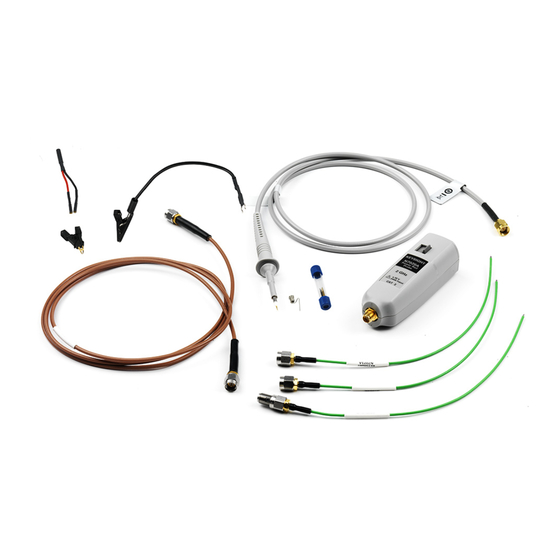
General Information Accessories Supplied Accessories The probe comes with the accessories shown in Figure Figure 3 Probe with Accessories N7020A User’s Guide... - Page 9 N7023A Power Rail Probe Browser, with accessories Ground spring 2.5 mm Ground lead 15 cm Spring-loaded probe tips 3 (One spring-loaded tip is pre-installed by Keysight into the N7023A browser.) Rigid probe tips Dual lead adapter † Micro SMD clip ‡...
- Page 10 N7021A pigtail cables or the coaxial N7022A main cable. To use this browser, replace the N7022A main cable attached to the N7020A power rail probe with the N7023A power rail probe browser as shown in the figure below.
- Page 11 This ensures that you can pick up a probe and immediately know which channel it is connected to without having to track the cable back to the oscilloscope channel input. N7020A User’s Guide...
- Page 12 Figure 4 Proper Tip Removal Technique You should exercise caution when using these sharp browser tips to avoid personal WARNING injury. N7020A User’s Guide...
- Page 13 General Information Orderable Accessories The orderable parts shown in this picture are listed in Table 3 on page 14. N7020A User’s Guide...
- Page 14 QFP IC-Clips 13 mm long down o 0960-2992 0.5 mm pitch (1 pair yellow/green) QFP IC-Clips short down to 0.5 mm 0960-2995 pitch (1 pair yellow/green) Ground Lead 15 cm 0960-2906 N4837A 2-leg Probe Positioner N2786-60001 N2786A Micro SMD Clip 1400-3652 N7020A User’s Guide...
-
Page 15: Inspecting The Probe
Sales Office. If the shipping container is damaged, or the cushioning materials show signs of stress, notify the carrier as well as your Keysight Technologies Sales Office. Keep the shipping materials for the carrier’s inspection. The Keysight Technologies office will arrange for repair or replacement at Keysight Technologies’ option without waiting for claim settlement. -
Page 16: Handling The Probe
The browser cable is a sensitive part of the N7023A power rail probe browser and, CAUTION therefore, you should be careful not to damage it through excessive bending or pulling. You should also avoid any mechanical shocks to this product in order to guarantee accurate performance and protection. N7020A User’s Guide... -
Page 17: Cleaning The Probe
General Information Cleaning the Probe Disconnect the N7020A power rail probe from the oscilloscope and clean the probe with a soft cloth dampened with a mild soap and water solution. Make sure that the probe is completely dry before reconnecting it to an oscilloscope. Avoid using abrasive cleaners and chemicals containing benzene or similar solvents. -
Page 18: Safety Information
To avoid electrical shock, do not operate this probe in wet or damp conditions. Do Not Operate in an Explosive Atmosphere. WARNING To avoid injury or fire hazard, do not operate this probe in an explosive atmosphere. N7020A User’s Guide... - Page 19 Do not use repaired fuses or short-circuited fuse holders. To do so could cause a shock or fire hazard. Capacitors inside the instrument may retain a charge even if the instrument is WARNING disconnected from its source of supply. N7020A User’s Guide...
-
Page 20: Returning The Probe For Service
Perform the following steps before shipping the probe back to Keysight Technologies for service. Contact your nearest Keysight sales office for information on obtaining an RMA number and return address. Write the following information on a tag and attach it to the malfunctioning equipment. -
Page 21: Contacting Keysight Technologies
General Information Contacting Keysight Technologies For technical assistance, contact your local Keysight Call Center. • In the Americas, call 1 (800) 829-4444 • In other regions, visit http://www.keysight.com/find/assist • Before returning an instrument for service, you must first call the Call Center at 1 (800) 829-4444. - Page 22 General Information N7020A User’s Guide...
-
Page 23: Using The N7020A
CAUTION in damage to the probe and to the oscilloscope’s input channel. If the N7020A input is connected to an S-series oscilloscope at vertical settings at or below NOTE 20 mV/div with more than 200 mV of applied offset with no signal on the probe input, the probe output may be indeterminate. -
Page 24: Requirements For Optimum Probe Performance
DUT must have extremely low source impedance, like that of a power rail. The N7020A has a non-flat input impedance that transitions from 50 kΩ at DC to 50Ω at 1 MHz and above. - Page 25 Using the N7020A To the DC component of a supply voltage, the N7020A probe presents a high impedance and thus low loading (about 50 kΩ). To the AC component of the supply voltage, the probe presents a low 50Ω impedance. This probe’s low input impedance, reduces noise on the probe’s output to the oscilloscope thus...
- Page 26 The N7020A power rail probe also provides a third connection method, using the N7023A N OTE power rail probe browser. This browser is connected to the N7020A probe by replacing the N7022A main cable. N7020A User’s Guide...
-
Page 27: Common Types Of Power Integrity Measurements
Using the N7020A Common Types of Power Integrity Measurements The following list some of the common types of power integrity measurements that you can perform using the N7020A probe: • Static and dynamic load response. Figure 7 Example of Response to Changing Load •... - Page 28 Using the N7020A • High frequency transients and noise. • PARD (Periodic and Random Disturbances) such as noise, ripple, and switching transients on power rails. Figure 8 Example of PARD on DC Output • Product electrical validation at extended temperatures.
-
Page 29: Connecting To The Dut
• N7020A probe with N7022A main cable • N7020A probe with the N7022A main cable and N7021A pigtail cable. Use the supplied SMA adapter to connect the two cables. • N7020A probe with the N7023A power rail probe browser (used in the same manner as a traditional passive probe). - Page 30 Using the N7020A Figure 9 Soldering the Probing End of The N7021A Cable Across a Bypass Capacitor To avoid accidentally shorting the circuit via the cable’s exposed ground, place a small CAUTION strip of non-conductive tape onto the board before attaching the coax. To avoid undue stress to the solder joints, tape the cable to the DUT.
-
Page 31: Avoiding Costly Repairs
Using the N7020A Avoiding Costly Repairs When connecting or using the probe, use caution to avoid damaging the oscilloscope’s channel input circuits due to electrostatic discharge (ESD). When the probe is connected to the oscilloscope, the CAUTION oscilloscope’s channel input circuits can be damaged by electrostatic discharge (ESD). - Page 32 Using the N7020A Figure 10 ESD Workstation N7020A User’s Guide...
-
Page 33: Calibrating
Keysight N7020A Power Rail Probe User’s Guide 3 Calibrating DC Attenuation/Offset Calibration Using N7022A Main Cable DC Attenuation/Offset Calibration Using N7023A Power Rail Probe Browser Always calibrate the probe before making any critical measurements. A probe calibration removes attenuation errors, offset errors, and timing delays that are introduced by the probe. -
Page 34: Dc Attenuation/Offset Calibration Using N7022A Main Cable
Calibrating DC Attenuation/Offset Calibration Using N7022A Main Cable Turn on the oscilloscope and connect the N7020A probe with the N7022A main cable attached to one of the oscilloscope’s input channels. Allow the oscilloscope and probe to warm up for 20 minutes. -
Page 35: Dc Attenuation/Offset Calibration Using N7023A Power Rail Probe Browser
Browser Turn on the oscilloscope and connect the N7023A power rail probe browser with the N7020A probe attached to one of the oscilloscope’s input channels. Allow the oscilloscope and probe to warm up for 20 minutes. If the oscilloscope needs calibration, perform a user calibration before the probe calibration. - Page 36 Calibrating N7020A User’s Guide...
-
Page 37: Specifications And Characteristics
Specifications and Characteristics Probe Dimensions The tables in this chapter list the specifications for the N7020A probe. Input Impedance DC is the only warranted specification. Connect the probe to a powered-on oscilloscope for at least 20 minutes before any testing to allow the probe to warm up. -
Page 38: Specifications And Characteristics
Specifications and Characteristics Specifications and Characteristics Table 4 N7020A Safety and Regulatory Information Description CEI/IEC 61010-031 CAT II This symbol indicates the Environmental Protection Use Period (EPUP) for the product’s toxic substances for the China RoHS requirements. The CE mark is a registered trademark of the European Community. ISM GRP 1-A denotes the instrument is an Industrial Scientific and Medical Group 1 Class A product. - Page 39 Mechanical Characteristics of the N7023A Power Rail Probe Browser Description Characteristics Weight (N7023A Power Rail Probe 26 g Browser only) Cable length Barrel Diameter 2.5 mm Table 8 Safety Specifications of N7020A Power Rail Probe Specification Low Voltage Directive 2006/95/EC CEI/IEC 61010-031:2008-08 N7020A User’s Guide...
-
Page 40: Probe Dimensions
Specifications and Characteristics Probe Dimensions Figure 12 Probe and Accessory Cable Dimensions N7020A User’s Guide... -
Page 41: Performance Plots
N7020A Input Impedance Equivalent Model This chapter includes plots that show the probe’s characteristic performance and an input impedance model of the probe. The performance characteristic plots in this chapter are for the N7020A probe with the N7022A main cable attached. -
Page 42: N7020A Performance Plots
Performance Plots N7020A Performance Plots Figure 13 Normalized Frequency Response, V , 2.5 GHz BW (N7020A with N7022A Main Cable) N7020A User’s Guide... - Page 43 Performance Plots Figure 14 Frequency Response for Different DUT Impedances (N7020A with N7022A Main Cable) N7020A User’s Guide...
- Page 44 Rise Time, Input Step (20/80%): ....... . . 169 ps Rise Time, N7020A with N7022A (10/90%): ......297 ps Rise Time, N7020A with N7022A (20/80%): .
- Page 45 Performance Plots Figure 16 Input Impedance Versus Frequency, Measured, Modeled (N7020A with N7022A Main Cable) N7020A User’s Guide...
-
Page 46: N7020A Input Impedance Equivalent Model
Performance Plots N7020A Input Impedance Equivalent Model The following Netlist is for the N7020A input impedance equivalent model shown Figure 17 on page 47. * source N7020A .EXTERNAL INPUT Vin .EXTERNAL OUTPUT Vout R_R3 GND N01679 590 T_T8 N01635 GND N01646 GND Z0=51.7174 TD=177.789ps T_T4 N01611 GND N01614 GND Z0=50.0323 TD=5.00049ns... - Page 47 Performance Plots Figure 17 Input Impedance Equivalent Model N7020A User’s Guide...
- Page 48 Performance Plots N7020A User’s Guide...
-
Page 49: Performance Verification
Keysight N7020A Power Rail Probe User’s Guide 6 Performance Verification Procedure Performance Test Record This chapter tests that the probe meets its specified input resistance, which is 50 kΩ±2%. Electrostatic discharge (ESD) can quickly and imperceptibly damage or destroy high CAUTION performance probes, resulting in costly repairs. -
Page 50: Procedure
Power on the DMM and select the 2-wire Ohm display on the DMM. Figure 18 Test Setup Read the DMM display for the input resistance. Record the result in Table 10 on page 51. To pass this test the result should be between 49 kΩ and 51 kΩ. N7020A User’s Guide... -
Page 51: Performance Test Record
Performance Verification Performance Test Record Serial #: Date: Tested by: Recommended Next Test Date: Table 10 Input Impedance Test Results Test Limits Result Pass/Fail Ω 50 k ± 2% N7020A User’s Guide... - Page 52 Performance Verification N7020A User’s Guide...
- Page 53 Probe Calibration dialog box, grounding probe, repair, resistance testing, returning for service, humidity, safety, Safety Considerations, input resistance, safety specifications, inspecting, safety warnings, service, static-safe accessories, Keysight Technologies, contacting, temperature, testing N7020A User’s Guide...
- Page 54 Index N7020A User’s Guide...
Need help?
Do you have a question about the N7020A and is the answer not in the manual?
Questions and answers