
Subscribe to Our Youtube Channel
Related Manuals for Satec EM132


Summary of Contents for Satec EM132
- Page 1 EM13x Series SMART MULTIFUNCTION METER Installation and Operation Manual BG0491 REV. A12...
-
Page 2: Limited Warranty
If the equipment is used in a manner not specified by SATEC LTD, the protection provided by the equipment may be impaired. For additional information regarding installation, operation or maintenance of this instrument, contact the manufacturer or your local representative or distributor. - Page 3 WARNING Read the instructions in this manual before performing installation and take note of the following precautions: 1. Ensure that all incoming AC power and other power sources are turned OFF before performing any work on the instrument. Protect the measurement AC Inputs voltage (V1, V2, V3) with 2A external overcurrent protection device and the power supply source inputs with 5A external overcurrent protection device, located close to the equipment.
- Page 4 Quick Start Guide This section can be used by a licensed electrician to install and perform basic EM13X setup. For more detailed EM13X Series setup and use instructions, see the following chapters in this manual. This quick start guide will assist you to have the unit running for the first time.
- Page 5 For direct connection, connect to CT wires through the meter CT terminals. Observe the arrow that indicates the current direction. In case of a retrofit application or high current external SATEC CT (or Split Core) where each external CT ends with two wires: ...
- Page 6 CT wiring To connect an Option module: Assemble the module on the meter. Power the EM13X Series unit on. Assembly a small module EM13x Series SMART MULTIFUNCTION METER...
- Page 7 Assembling the 12DI/4RO module To operate the EM13X Series: Perform device diagnostics. Configure the device through the EM13X Series unit front panel display Configuring the EM13X Series remotely Install the PAS application software on your PC. Configure the PAS database for your meter.
-
Page 8: Table Of Contents
C hapter 1 General Information Features Table of Contents Chapter 1 General Information ................11 Features ........................13 Available Options .......................14 Digital I/O ......................15 Analog Output ...................... 15 Additional Communication Port– COM2 ..............15 Customized Options ....................16 Device Resolution ....................16 Display Options ..................... - Page 9 General C hapter 1 Information Features Navigating in Data Display Mode ................58 Display Features ....................58 Measurement Units ....................59 Data Displays ......................59 TEST Mode Data Display ..................59 Billing Period Energy Data Displays ................. 59 TOU/Maximum Demand Power Data Display ............61 Instrumentation Measurement Maximum Demand Data Display .........
- Page 10 C hapter 1 General Information Features Viewing and Clearing Device Diagnostics ............118 Viewing Communication Status and Statistics..........118 Remote Relay Control .................... 119 Upgrading Device Firmware ................. 120 Chapter 7 Monitoring Meters ................122 Viewing Real-time Data ..................122 Viewing Real-time Min/Max Log .................
-
Page 11: Chapter 1 General Information
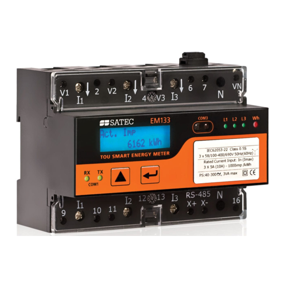
The EM13X Series offers standard voltage, current, power and frequency measurements, amp-demand, energy measurements and data logging, harmonic analysis and control capabilities. The EM13X Series consists of three different models series: EM132/EM133 with AC/DC Auxiliary Power Supply (40-318V AC/DC) ‒ EM132/EM133-5, internal transformer... - Page 12 (secondary current): In = 20mA, Imax = 40mA EM132/EM133-21DC with DC Auxiliary Power Supply (9-36 VDC) ‒ EM132/EM133-21DC-5, internal CT, transformer operated configuration with current inputs: In = 5A, Imax = 10A ‒...
-
Page 13: Features
General C hapter 1 Information Features 1.1 Features Multifunctional 3-phase Power Meter 3 voltage inputs and 3 current transformer-isolated AC inputs for direct connection to power line or via potential and current transformers True RMS, volts, amps, power, power factor, neutral current, voltage and current unbalance, frequency ... -
Page 14: Available Options
Standard 2-wire RS-485 communication port; MODBUS RTU, DNP3, SATEC ASCII and IEC 60870-5-101 communication protocols Optional second communication port; MODBUS RTU, MODBUS/TCP, DNP3, DNP3/TCP, SATEC ASCII, PROFIBUS DP, CANopen and IEC 60870-5-104 (over TCP) communication protocols eXpertPower client for communicating with the SATEC proprietary eXpertPower... -
Page 15: Digital I/O
PROFIBUS DP port CANopen port RS-232/RS-422/RS-485 port; MODBUS RTU, DNP3 or IEC 60870-5- 101, and SATEC ASCII communication protocols; GPRS or 3G/4G cellular communications port; MODBUS/TCP protocol RF communication; MODBUS RTU protocol EM13x Series SMART MULTIFUNCTION METER... -
Page 16: Customized Options
C hapter 1 General Information Customized Options 1.3 Customized Options Presentation of data on the front display and via communications can be customized to best suit the user application. Device Resolution A low or high-resolution option can be selected for the presentation of voltage, current, and power for use in high and low power applications. -
Page 17: Measured Parameters
General C hapter 1 Information Measured Parameters 1.4 Measured Parameters Table 1: Measured and Displayed Parameters Parameter Display Comm. Analog Pulse Alarm 1-cycle Real-time Measurements RMS Voltage per phase RMS Current per phase kW per phase ... - Page 18 C hapter 1 General Information Parameter Display Comm. Analog Pulse Alarm kvar Maximum Demand Import kvar Maximum Demand Export kVA Maximum Demand Total Energy Total kWh Import & Export ...
-
Page 19: Labelling
General C hapter 1 Information Labelling 1.5 Labelling Figure 1 -1 EM133 label – UL marking Figure 1 -2 EM133 label – NMI marking Figure 1 -3 EM133 label – CE MID marking EM13x Series SMART MULTIFUNCTION METER... -
Page 20: Chapter 2 Installation
C hapter 2 Site Requirements Installation Chapter 2 Installation This chapter discusses the following types of physical installations for the EM13X Series SMART MULTIFUNCTION METER: Mechanical Installation Electrical Installation I/O Connections COM Port Connections. 2.1 Site Requirements ... - Page 21 Installation C hapter 2 Mechanical Installation Figure 2 -1 Dimensions EM13x Series SMART MULTIFUNCTION METER...
-
Page 22: Wall Mounting
C hapter 2 Mechanical Installation Installation Wall Mounting To mount the meter on the wall: Position the meter on the wall according to hole locations as shown in figure 2-2 Affix the meter using washers and nuts. Figure 2 -2. Surface Mounting EM13x Series SMART MULTIFUNCTION METER... -
Page 23: Din Rail Mounting
Installation C hapter 2 Mechanical Installation DIN Rail Mounting The EM13X Series can be mounted on a standard 35-mm DIN rail as shown in figure 2-3 Figure 2 -3. EM13X Series DIN Rail Mounting EM13x Series SMART MULTIFUNCTION METER... -
Page 24: Add-On Module Mounting
C hapter 2 Mechanical Installation Installation Add-On Module Mounting Before Add-On Module installation ensure that all incoming power sources are shut OFF. Failure to observe this practice can result in serious or even fatal injury and damage to equipment. Turn off the EM13X Series auxiliary power supply or voltage supply inputs (SE model). -
Page 25: Electrical Installation
All conductors must be stranded copper. All conductors and insulation systems and crimped devices must be appropriate for the application. SATEC requires using crimped ferrules on stranded wire. Table 3 below summarizes the different conductors’ sizes to be used in the EM133 external connections. -
Page 26: Typical Installation
C hapter 2 Electrical Installation Installation Typical Installation Figure 2 -6a Typical Installation Diagram with Auxiliary Power Supply EM13x Series SMART MULTIFUNCTION METER... - Page 27 Installation C hapter 2 Electrical Installation 1. SATEC RF chokes to be installed between CBR and Meter Voltage Inputs in residential area or other places require ANCI C12.20 compliance. Otherwise it may be bypassed. 2. AC0242 shall be routed with the voltage lines (bundled), separately from communication &...
- Page 28 C hapter 2 Electrical Installation Installation Figure 2 -6c Typical Installation Diagram with Self Energized Power Supply – direct connection EM13x Series SMART MULTIFUNCTION METER...
- Page 29 Installation C hapter 2 Electrical Installation 1. SATEC RF chokes to be installed between CBR and Meter Voltage Inputs in residential area or other places require ANCI C12.20 compliance. Otherwise it may be bypassed. 2. AC0242 shall be routed with the voltage lines (bundled), separately from communication &...
- Page 30 C hapter 2 Electrical Installation Installation Figure 2 -6e Typical Installation Diagram with 12/24 VDC Auxiliary Power Supply EM13x Series SMART MULTIFUNCTION METER...
-
Page 31: Terminals
C hapter 2 Electrical Installation Terminals The EM132/133/133-SE terminals are constructed as a built-in part of the meter equipment. The terminals are divided in two different terminal categories: 1) High power terminal, dedicated to current terminals only, with a torque rating of 2.0-2.3Nm... -
Page 32: Power Source Connection
C hapter 2 Electrical Installation Installation Figure 2 -7b Terminals View EM133-SE Model Power Source Connection The equipment installation shall conform to the following instructions: a) a switch or circuit-breaker shall be included in the building installation as close as possible to the equipment supply voltage;... - Page 33 Installation C hapter 2 Electrical Installation Figure 2 -8 EM13X Series Auxiliary Power Supply connection EM13x Series SMART MULTIFUNCTION METER...
-
Page 34: Voltage Input Connection
C hapter 2 Electrical Installation Installation Voltage Input connection The equipment installation shall conform to the following instructions: a) a switch or circuit-breaker shall be included in the building installation as close as possible to the equipment supply voltage; b) It shall be in close proximity to the equipment and within easy reach of the OPERATOR;... -
Page 35: Current Input Connection
Connection, in EM133-SE model Current Inputs and Voltage Inputs are internally connected together 20mA nominal current (40mA maximum) using HACS (external CT provided by SATEC) – Transformer Connection 2.5mA nominal current (5mA maximum) using RS5 (external CT provided by SATEC) – Transformer Connection Figure ... -
Page 36: Wiring Diagrams
C hapter 2 Electrical Installation Installation Wiring Diagrams For AC input ratings, see Technical Specifications in Appendix A for more details. Table 3 presents the available wiring configurations in the meter. Table 3: Wiring Configurations Wiring Configuration Setup Code Figure 3-wire 2-element Delta direct connection using 2 CTs 3dir2... - Page 37 Installation C hapter 2 Electrical Installation Figure 2 -12 3-Wire 2-Element Delta Direct Connection Using 2 CTs (Wiring Mode = 3dir2) EM13x Series SMART MULTIFUNCTION METER...
- Page 38 C hapter 2 Electrical Installation Installation Figure 2 -13 4-Wire Wye 3-Element Direct Connection Using 3 CTs (Wiring Mode = 4LL3 or 4Ln3) EM13x Series SMART MULTIFUNCTION METER...
- Page 39 Installation C hapter 2 Electrical Installation Figure 2 -14 4-Wire Wye 3-Element Connection Using 3 PTs, 3 CTs (Wiring Mode = 4LL3 or 4Ln3) Figure 2 -15a 3-Wire 2-Element Open Delta Connection Using 2 PTs, 2 CTs (Wiring Mode = 3OP2) EM13x Series SMART MULTIFUNCTION METER...
- Page 40 C hapter 2 Electrical Installation Installation Figure 2 -15b 3-Wire 2-Element Open Delta Connection Using 3 PTs, 2 CTs (Wiring Mode = 3OP2) This configuration provides accurate power measurements only if the voltages are balanced. Figure 2 -16 4-Wire Wye 2½-Element Connection Using 2 PTs, 3 CTs (Wiring Mode = 3LL3 or 3Ln3) EM13x Series SMART MULTIFUNCTION METER...
- Page 41 Installation C hapter 2 Electrical Installation Figure 2 -17 3-Wire 2½-Element Open Delta Connection Using 2 PTs, 3 CTs (Wiring Mode = 3OP3) Figure 2 -18 4-Wire 3-Element Delta Direct Connection Using 3 CTs (Wiring Mode = 4LL3 or 4Ln3) EM13x Series SMART MULTIFUNCTION METER...
- Page 42 C hapter 2 Electrical Installation Installation Figure 2 -19 3-Wire 2½-Element Broken Delta Connection Using 2 PTs, 3 CTs (Wiring Mode = 3bLn3 or 3bLL3) EM13x Series SMART MULTIFUNCTION METER...
-
Page 43: Battery Replacement
Installation C hapter 2 Battery Replacement 2.5 Battery Replacement WARNING! Only qualified personnel familiar with the instrument and its associated electrical equipment must perform the RTC battery backup replacement. The battery replacement must be performed while equipment power supply is "ON" To replace the CR2032 RTC battery: 1) Remove the EM13X Series cover 2) Remove the old battery by lifting up the battery holder retractable... -
Page 44: I/O Connections
C hapter 2 I/O Connections Installation 2.6 I/O Connections Before I/O Module installation ensure that all incoming power sources are shut OFF. Failure to observe this practice can result in serious or even fatal injury and damage to equipment. For I/O ratings, see Technical Specifications in Appendix A. -
Page 45: 4Di/2Ro Module
Installation C hapter 2 I/O Connections 4DI/2RO Module Before I/O Module installation ensure that all incoming power sources are shut OFF. Failure to observe this practice can result in serious or even fatal injury and damage to equipment. Figure 2 -10 4DI/2RO Module Assembly Relay Outputs There are two relay outputs provided for energy pulsing, alarms, or remote control. -
Page 46: Di Module
C hapter 2 I/O Connections Installation 8 DI module Eight optically isolated status inputs are provided for status monitoring, pulse counting, external power demand period, time synchronization Figure 2 -13 8 DI - Digital Input Connection 12DI/4RO Module The 12DI/4RO module can be equipped with optional communication port COM2 –... -
Page 47: 4Ao Module - Analog Outputs
Installation C hapter 2 I/O Connections Figure 2 -15 Relay Output Connection Digital Inputs 12 optically isolated status inputs are provided for status monitoring, pulse counting, external power demand period, time synchronization. Figure 2 -16 12 Digital Input Connection 4AO Module - Analog Outputs The 4AO module has four optically isolated analog outputs with an internal power supply and current output options of 0-20 mA and 4-20... - Page 48 C hapter 2 I/O Connections Installation Figure 2 -17 4AO Module Assembly Figure 2 -18 Analog Output Connection It is recommended to connect unused Analog output channels to Common terminal. The 4AO module TERMINAL is for use only with equipment which has no live parts which are ACCESSIBLE The RATING of the insulation of the external equipment for use with the 4AO module, shall comply according to Installation...
-
Page 49: Communications Connections
Installation C hapter 2 Communications Connections 2.7 Communications Connections Before installing the Communication Module, ensure that all incoming power sources are shut OFF. Failure to observe this practice can result in serious or even fatal injury and damage to equipment. Several communication options are available for the EM13X Series: ... -
Page 50: Connection
C hapter 2 Communications Connections Installation RS-485 Connection RS-485 COM1 Figure 2 -19 COM1 RS-485 2-Wire Connection Communication cable Specification: Shielded, #22AWG. Note: pay attention to GND connection (SH->GND). EM13x Series SMART MULTIFUNCTION METER... -
Page 51: Eth Module - Com2 Ethernet Connection
Installation C hapter 2 Communications Connections ETH module – COM2 Ethernet Connection Figure 2 -20 COM2 Ethernet Connection The ETH module TERMINAL is for use only with equipment which has no live parts which are ACCESSIBLE The RATING of the insulation of the external equipment for use with the ETH module, shall comply according to Installation Category III for insulation to be suitable for SINGLE FAULT CONDITION... -
Page 52: Pro Module - Com2 Profibus Connection
C hapter 2 Communications Connections Installation PRO module – COM2 PROFIBUS Connection Figure 2 -21 COM2 PROFIBUS Connection The PRO module TERMINAL is for use only with equipment which has no live parts which are ACCESSIBLE The RATING of the insulation of the external equipment for use with the PRO module, shall comply according to Installation Category III for insulation to be suitable for SINGLE FAULT ... -
Page 53: Canopen Module - Com2 Canopen Connection
Installation C hapter 2 Communications Connections CANopen module – COM2 CANopen Connection RS-232/422-485 module – COM2 Connection Figure 2 -22 COM2 RS-232 connection EM13x Series SMART MULTIFUNCTION METER... -
Page 54: Connecting A Gsm/Gprs/3G Module
C hapter 2 Communications Connections Installation Figure 2 -23 COM2 RS-422/485 connection The RS-232/422-485 module TERMINALS are for use only with equipment which has no live parts which are ACCESSIBLE The RATING of the insulation of the external equipment for use with The RS-232/422-485 module, shall comply according to Installation Category III for insulation to be suitable for SINGLE FAULT CONDITION... -
Page 55: Connecting An Rf Module
Installation C hapter 2 Communications Connections The GSM/GPRS SIM must not have any incoming voice call. The customer must require from the Service Provider for DATA services only The GPRS modem module can be equipped with two different antennas: internal Antenna for installation into plastic closet or no-metallic environment. -
Page 56: Chapter 3 Using Front Display
C hapter 3 Using Front Display Communications Connections Chapter 3 Using Front Display This chapter provides EM13X Series SMART MULTIFUNCTION METER front panel information and operating procedures. Figure 3 -1: EM13X Series Unit Energy Pulse LED The EM13X Series has a red “Energy Pulse” LED. It flashes at a constant rate when a load is applied to the meter. -
Page 57: Display Operations
Using C hapter 3 Front Display Display Operations 3.1 Display Operations The EM13X Series has a high-contrast graphical LCD display with backlight for local data read outs, meter setup and servicing. The display operates in two modes: Multi-page data display mode with Auto-Scroll feature allows you to scroll through display screens and pages to view various billing, instrumentation and status data. -
Page 58: Navigating In Data Display Mode
C hapter 3 Using Front Display Display Operations Navigating in Data Display Mode The following table gives a summary of the button operations in data display mode. Button Press Operations SCROLL Short press Scroll through pages SELECT/ENTER Short press Scroll through displays SELECT/ENTER Long press... -
Page 59: Measurement Units
Using C hapter 3 Front Display Data Displays Measurement Units The following table shows the display resolution for common displayed quantities. All measured data is displayed in primary units. Measured Voltage Connection Units and Display Resolution Quantity Energy kWh, kvarh, kVAh with one decimal place. - Page 60 C hapter 3 Using Front Display Data Displays The following example demonstrates the present billing period displays for two configured billing registers (kWh imported and kvarh imported) and for three active tariff rates. The actual register contents in your installation may be different depending on your selection of register sources.
-
Page 61: Tou/Maximum Demand Power Data Display
Using C hapter 3 Front Display Data Displays Tariff 2 Import Phase 1 active energy data. Tariff 3 Import Phase 1 active energy data. Total Import Phase 2 active energy data Tariff 1 Import Phase 2 active energy data. Tariff 2 Import Phase 2 active energy data. - Page 62 C hapter 3 Using Front Display Data Displays DISPLAY Description Total Import Max. DMD active power data (Reg1 for TOU/Max. DMD actve power, Reg 1 Imp Reg2 for TOU/Max. DMD reactve power predefined TOU/Register factory setup, 0.008 kW can be changed by user, see Configuring Billing/Tariff Registers Configuring the...
-
Page 63: Instrumentation Measurement Maximum Demand Data Display
Using C hapter 3 Front Display Data Displays Instrumentation Measurement Maximum Demand Data Display Maximum demand displays show engineering maximum demands (not billing maximum demands) for import/export powers, voltages, and currents. DISPLAY Description MAX. DMD Total Import Max. DMD active power data P Imp 0.008 kW MAX. -
Page 64: Instrumentation Measurement
C hapter 3 Using Front Display Data Displays MAX. DMD Max. DMD Phase 3 voltage data Instrumentation Measurement Instrumentation Measurements represent general instrumentation data you can use while installation and inspecting the meter. Use phase angles displays to check the order of phases when connecting wires to the meter terminals. - Page 65 Using C hapter 3 Front Display Data Displays DISPLAY Description L1 S 0 kVA Phase 1 apparent power and power factor L1 PF L2 P 0 kW Phase 2 active and reactive power L2 Q 0 kvar L2 S 0 kVA Phase 2 apparent power and power factor L2 PF...
-
Page 66: Status Inputs And Outputs
C hapter 3 Using Front Display Data Displays DISPLAY Description H1/L3 0 kVA First Harmonic Phase 3 apparent power and power factor H1/L3 0 PF V1 THD Phase 1 voltage and current THD I1 THD V2 THD Phase 2 voltage and current THD I2 THD V3 THD Phase 3 voltage and current THD... -
Page 67: Device Info Display
Using C hapter 3 Front Display Data Displays DISPLAY Description Phase Rotation: Phase rotation order (Error, Positive, Negative) Error 123456 Digital Inputs status 000000 Relays: Relays control status Counter 1: Status/Event Counter 1 Counter 2: Status/Event Counter 2 Counter 3: Status/Event Counter 3 Counter 4: Status/Event Counter 4... - Page 68 C hapter 3 Using Front Display Data Displays DISPLAY Description S/N: 12345744 Meter identification info, serial number and device SW version S/W: V12.1.1 Boot: V1.1.1 Boot SW version and Modem setup Modem: N/A COM1: a221,b115.2 Communication port COM1 info Modbus RTU COM2: RF, a221 Communication port COM2 info...
-
Page 69: Programming Mode
Using C hapter 3 Front Display Programming Mode 3.3 Programming Mode To enter programming mode from the data display, press and hold the SELECT/ENTER button for more than 5 seconds. Navigation Buttons The following table gives a summary of the button operations in programming mode. - Page 70 C hapter 3 Using Front Display Programming Mode functions listed in the following table. Access to particular menus is granted depending on the security level of the password you entered. Menu Menu Function Security Level Label View Change Reset Reset of billing and engineering maximum demands, device diagnostics, meter and failure Table...
-
Page 71: Viewing And Changing Setup Options
Using C hapter 3 Front Display Programming Mode Viewing and Changing Setup Options Once you entered a correct password you are moved to the main Enter Password meter menu. 00000000 The main menu has two windows: the left window displays a submenu SHORT PRESS list, while the right window is an assisting Exit window that allows easy Enter Password... -
Page 72: Chapter 4 Using Pas Software
C hapter 4 Using PAS Software Installing PAS Chapter 4 Using PAS Software The support PAS software is a configuration and data acquisition tool that allows you to configure all of the EM13X Series features, monitor your meters on-line, retrieve recorded files and view reports. PAS can communicate with your EM13X Series via a serial port and via the Ethernet. - Page 73 Using C hapter 4 PAS Software Creating a New Site for your Meter Figure 4 -1: Configuration Dialog Box – Instrument Setup Tab Click the Sites button on the right-hand-side. From the Look in box, select the directory where a new database will be stored.
-
Page 74: Chapter 5 Configuring The Em13X Series
C hapter 5 Configuring the EM13X Series Configuring Communications Chapter 5 Configuring the EM13X Series This chapter describes how to configure the EM13X Series for your particular environment and application from the front display and via PAS. To access your meter configuration options via PAS, you should create a site database for your device as shown in Chapter 4. - Page 75 Table 4: COMPort Options Display Label Parameter Options Default Description Protocol Communication MODBUS RTU, MODBUS MODBUS RTU protocol ASCII, DNP3, SATEC (COM 1-3) communications ASCII, IEC 60870-5 protocol for the port Interface Port interface RS485, RS232, IR, RS485 Not changeable;...
-
Page 76: Setting Up The Ethernet
C hapter 5 Configuring the EM13X Series Configuring Communications Setting up the Ethernet Using the Front Display Select Net from the main menu. See Viewing and Changing Setup IP Address Options in Chapter 3 for information on navigating in menus. 192.168.000.203 See the table below for available network options. -
Page 77: Setting Up Gprs Network
Configuring C hapter 5 the EM13X Series Configuring Communications may need to wait some additional time until PAS restores a connection with your device.Setting-Up Dial-Up GPRS Network Setting up GPRS Network Using the Front Display The EM13X Series can provide wireless GPRS communications with the remote Modbus/TCP server via an external Enfora GSM1308 SA-G+ GSM/GPRS modem. -
Page 78: Setting Up Expertpower Client
– SATEC proprietary Internet services. Connections to the eXpertPower server are handled on a periodic basis. To set up communications with the eXpertPower server, select Communication Setup from the Meter Setup menu, and then click on the ExpertPower Client Setup tab. -
Page 79: Setting Up Tcp Notification Client
Configuring C hapter 5 the EM13X Series Configuring Communications Figure 5 -4: eXpertPower Client Setup Tab The following table lists available options. Refer to your eXpertPower service provider for the correct network settings. Table 6: eXpertPower Client Setup Options Parameter Options Default... -
Page 80: General Meter Setup
C hapter 5 Configuring the EM13X Series General Meter Setup Table 7: TCP Notification Client Setup Options Parameter Options Default Description Client Enabled NO, YES Enables operations of the notification client Server IP Address 192.168.0.3 The IP address of the notification server ServerPort 0-65535... - Page 81 Configuring C hapter 5 the EM13X Series General Meter Setup Using PAS Select General Setup from the Meter Setup menu. See the table below for the Basic Setup options. Table 8: Basic Setup Options Display Parameter Options Default Description Label Conf Wiring Mode...
- Page 82 C hapter 5 Configuring the EM13X Series General Meter Setup Figure 5 -6: General Setup Dialog Box – Basic Setup Tab Table 9 lists the available wiring modes. Table 9: Wiring Modes Wiring Mode Description 3OP2 3-wire Open Delta using 2 CTs (2 element) 4LN3 4-wire Wye using 3 PTs (3 element), line-to-neutral voltage readings 3DIR2...
-
Page 83: Device Options
Configuring C hapter 5 the EM13X Series General Meter Setup Device Options The Device Options setup allows changing user-configurable device options or putting the meter into energy test mode. Using the Front Display Select Options from the main menu. See Viewing and Changing Setup Options TestMode... -
Page 84: Configuring Digital Inputs
C hapter 5 Configuring the EM13X Series General Meter Setup Figure 5 -7: General Setup Dialog Box – Device Options Tab Power Calculation Modes The power calculation mode option allows you to change the method for calculating reactive and apparent powers in presence of high harmonics. - Page 85 Configuring C hapter 5 the EM13X Series General Meter Setup Using PAS Select General Setup from the Meter Setup menu, and then click on the Digital Inputs tab. Figure 5 -8: General Setup Dialog Box – Digital Inputs Dialog Box The available options are shown in Table 11.
-
Page 86: Configuring Relay Outputs
C hapter 5 Configuring the EM13X Series General Meter Setup Table 11: Digital Inputs Options Parameter Options Default Description Input Polarity NORMAL NORMAL For the normal polarity, the open INVERTING to closed transition is considered closed. For the inverting polarity, the closed to open transition is considered a closed Pulse Input... - Page 87 Configuring C hapter 5 the EM13X Series General Meter Setup Figure 5 -9: General Setup Dialog Box – Relay Outputs Tab EM13x Series SMART MULTIFUNCTION METER...
- Page 88 C hapter 5 Configuring the EM13X Series General Meter Setup The available relay outputs options are shown in Table 12. Table 12: Relay Output Options Parameter Options Default Description Operation UNLATCHED UNLATCHED Unlatched mode: the relay mode LATCHED goes into its active state PULSE when the control setpoint is in active (operated) state,...
-
Page 89: Configuring Analog Outputs
Configuring C hapter 5 the EM13X Series General Meter Setup Generating Energy Pulses through Relay Outputs To generate energy pulses through a relay output: Set a relay to either pulse, or KYZ mode, and then select a polarity (active pulse edge) for energy pulses and a pulse width. - Page 90 C hapter 5 Configuring the EM13X Series General Meter Setup The available analog output options are described in Table 13. Table 13: Analog Output Options Option Range Description AO type 0-1mA The analog output type. When connected ±1mA to the meter, shows the actual AO type 0-20mA received from the device.
-
Page 91: Configuring Counters
Configuring C hapter 5 the EM13X Series General Meter Setup The meter does not allow access to the low scale setting if the parameter is directional. Whenever the sign of the output parameter is changed to negative, the meter automatically uses the full engineering scale setting for +1 mA with a negative sign. - Page 92 C hapter 5 Configuring the EM13X Series General Meter Setup Figure 5 -11: General Setup Dialog Box – Pulse/Event Counters Table 14 lists available counter options. Table 14: Counter Options Option Range Default Description Pulse Input None, None Links a digital input to the counter DI14...
-
Page 93: Configuring Alarm/Control Setpoints
Configuring C hapter 5 the EM13X Series General Meter Setup Configuring Alarm/Control Setpoints The EM13X Series has an embedded logical controller that can perform different actions in response to user-defined internal and external events. Unlike a PLC, the meter uses a simplified programming technique based on setpoints that allows the user to define a logical expression based on measured analog and digital values that produce a required action. - Page 94 C hapter 5 Configuring the EM13X Series General Meter Setup The following table lists the available setpoint options. Table 15: Setpoint Options Option Range Description Trigger See Appendix C The trigger parameter that is used as an parameter argument in the logical expression Operate limit The threshold (in primary units) at which the conditional expression would be...
- Page 95 Configuring C hapter 5 the EM13X Series General Meter Setup setpoint alarm status until explicitly cleared through communications or via the display. A programmable action is performed on setpoint status transition when a setpoint event is asserted. Generally, setpoint actions are performed independently for each setpoint and can be repeated a number of times for the same target.
-
Page 96: Configuring The Display
C hapter 5 Configuring the EM13X Series General Meter Setup Configuring the Display This setup allows configuring the meter display. It also has an entry for launching the meter Flash Loader. Using the Front Display Select the Disp entry from the main menu. See Viewing and Changing Setup Options in Chapter 3 for information on configuring parameters... - Page 97 Configuring C hapter 5 the EM13X Series General Meter Setup Using PAS Select General Setup from the Meter Setup menu, and then click on the Display Setup tab. Figure 5 -13: General Setup Dialog Box – Display Setup Tab The available options are listed in the table 17 below.
-
Page 98: Local Time Settings
C hapter 5 Configuring the EM13X Series General Meter Setup Table 17: Display Setup Options Display Label Parameter Options Default Description Auto-Scroll Auto-Scroll Disabled, Defines the display Interval 2-10, 15, 20, scroll interval or 25, 30 seconds disables auto-scroll Scroll Seq. - Page 99 Configuring C hapter 5 the EM13X Series General Meter Setup Figure 5 -14: General Setup Dialog Box – Local Settings Tab The available options are described in Table 18. Table 18: Local Time Options Display Parameter Options Default Description Label Date Order...
-
Page 100: Configuring Meter Security
C hapter 5 Configuring the EM13X Series Configuring Meter Security Display Parameter Options Default Description Label End Week DST End Week to 4 and last First The 1 week of the month when Daylight Saving Time ends. End Day DST End Day The weekday Sunday... - Page 101 Configuring C hapter 5 the EM13X Series Configuring Meter Security To change the password: Apply LONG PRESS on ENTER button to select the Passwrd 1 entry Access Passwrd 1 Apply SHORT PRESS on ENTER button to select the password digit to change.
-
Page 102: Configuring Billing/Tou
C hapter 5 Configuring the EM13X Series Configuring Billing/TOU 5.4 Configuring Billing/TOU Billing Energy Registers The EM13X Series has 4 fully programmable billing energy registers that can be linked to any internal energy source or to an external pulse source that delivers pulses through the meter digital inputs. - Page 103 Configuring C hapter 5 the EM13X Series Configuring Billing/TOU Figure 5 -16: Energy/TOU Setup Dialog Box – Billing/TOU Registers tab Configure the register options according to the valid parameters shown in Table 19. Table 19: Billing/TOU Register Options Parameter Options Default...
-
Page 104: Configuring The Daily Tariff Schedule
C hapter 5 Configuring the EM13X Series Configuring Billing/TOU Configuring the Daily Tariff Schedule To configure your daily tariff schedule, select Energy/TOU from the Meter Setup menu, and then click on the TOU Daily Profiles tab. Figure 5 -17: Energy/TOU Setup Dialog Box – TOU Daily Profiles Tab The daily profile setup allows you to specify the daily tariff change points with a 15-minute resolution for 4 seasons using 4 different daily schedules for each season. -
Page 105: Configuring The Season Tariff Schedule
Configuring C hapter 5 the EM13X Series Configuring Billing/TOU Configuring the Season Tariff Schedule To configure your season tariff schedule, select Energy/TOU from the Meter Setup menu, and then click on the TOU Calendar tab. Figure 5 -18: TOU Calendar Setup Dialog Box – TOU Calendar Tab The meter TOU calendar allows you to configure any tariff schedule based on any possible utility regulation. -
Page 106: Configuring Recorders
C hapter 5 Configuring the EM13X Series Configuring Recorders 5.5 Configuring Recorders The EM13X Series has a 125-KByte onboard non-volatile memory for data and event recording. The memory is fully configurable and can be freely partitioned between log files. The meter provides memory for a total of 3 log files: ... - Page 107 Configuring C hapter 5 the EM13X Series Configuring Recorders To change the file properties or to create a new file: Double click on the file you want to change. Select desired parameters for your log. Click OK. For your reference, the record size and the number of records available for your file are reported in the dialog box.
-
Page 108: Configuring The Event Recorder
C hapter 5 Configuring the EM13X Series Configuring Recorders Configuring the Event Recorder To configure the Event log file: Double click on the Event Log file partition with the left mouse button. Select a desired file type for your file. Select the maximum number of records you want to be recorded in the file. - Page 109 Configuring C hapter 5 the EM13X Series Configuring Recorders Click OK, and then send your new setup to the meter, or save to the device database. To define the contents of the file: Highlight the data log file row with the left mouse button, and then click on the Setup Recorder button, or click on the Data Recorder tab and select the corresponding log number.
- Page 110 C hapter 5 Configuring the EM13X Series Configuring Recorders Double click on the Data Log#16partition with the left mouse button. Select the TOU Daily Profile file type. Select the number of season tariffs in your TOU schedule. Add one additional parameter if you selected to record the Summary (TOU total) registers as well.
-
Page 111: Configuring Communication Protocols
Configuring C hapter 5 the EM13X Series Configuring Communication Protocols 5.6 Configuring Communication Protocols This section describes how to customize protocol options for use with your application software. Configuring Modbus Modbus Point Mapping The EM13X Series provides 120 user assignable registers at addresses 0 to 119. -
Page 112: Configuring Dnp3
C hapter 5 Configuring the EM13X Series Configuring Communication Protocols Changing 32-bit Register Format The EM13X Series allows you to read 32-bit Modbus analog registers, energy counters and binary counters either in integer format, or in IEEE single precision floating point format. The 32-bit MODBUS registers are factory-set to integer format. - Page 113 Configuring C hapter 5 the EM13X Series Configuring Communication Protocols Table 20: DNP Options Parameter Options Default Description Binary Inputs (BI) Binary Input Object Single-bit Single-bit The default BI object variation for With Status requests with qualifier code 06 when no specific variation is requested Analog Inputs (AI) Analog Input Object...
- Page 114 C hapter 5 Configuring the EM13X Series Configuring Communication Protocols If the scaling unit is greater than 1, the counter value is reported being divided by the selected scaling unit from 10 to 1000. To get the actual value, multiply the counter reading by the scaling unit. Configuring DNP Class 0 Responses The most common method of getting static object information from the meter via DNP is to issue a read Class 0 request.
-
Page 115: Chapter 6 Device Control And Upgrading
Device C hapter 6 Control and Upgrading Resetting Accumulators, Maximum Values and Files Chapter 6 Device Control and Upgrading This section describes operations on the meter you can perform from the front display or via PAS. To access device control options from PAS, you should have your meter online. - Page 116 C hapter 6 Device Control and Upgrading Resetting Accumulators, Maximum Values and Files Figure 6 -1: Reset Dialog To reset the desired values or files: Click on the corresponding button, and then confirm your command. If an entry has more than one target, you are allowed to select targets to reset.
-
Page 117: Updating The Meter Clock
Device C hapter 6 Control and Upgrading Updating the Meter Clock 6.2 Updating the Meter Clock Using the Front Display Select the RTC entry from the main menu. To change the time or date: Reset Exit When in RTC setup menu, applying a LONG PRESS on the SELECT/ENTER button will display the Time/Date screen while Time SCROLL until RTC menu... -
Page 118: Viewing And Clearing Device Diagnostics
C hapter 6 Device Control and Upgrading Viewing and Clearing Device Diagnostics 6.3 Viewing and Clearing Device Diagnostics Using the Front Display Diagnostics Display in Chapter 3 on how to view and clear device diagnostics from the front display. Using PAS Ensure that the On-line button on the PAS toolbar is checked, select Device Control from the Monitor menu, and then click on the Device... -
Page 119: Remote Relay Control
Device C hapter 6 Control and Upgrading Remote Relay Control Figure 6 -5: Device Control Dialog Box – Communications Tab This window indicates the present GPRS communication status (see Setting Up GPRS Network in Chapter 5) and connection statistics of the TCP clients (see Setting Up eXpertPower Client Setting Up TCP... -
Page 120: Upgrading Device Firmware
C hapter 6 Device Control and Upgrading Upgrading Device Firmware Figure 6 -6: Device Control Dialog Box – Remote Relay Control Tab To send a remote command to a relay: Select a desired command in the Relay Command box for a relay: OPERATE –... - Page 121 Device C hapter 6 Control and Upgrading Upgrading Device Firmware You are asked for the password regardless of the password protection setting in your meter. Type the meter password, and click OK. If you did not change the password in the meter, enter the default password Wait until PAS completes upgrading your device.
-
Page 122: Chapter 7 Monitoring Meters
C hapter 7 Monitoring Meters Viewing Real-time Data Chapter 7 Monitoring Meters 7.1 Viewing Real-time Data Real-time data can be continuously retrieved from your devices and updated on the screen at the rate you defined in the Instrument Setup. To get real-time data from your meter: Ensure that the On-line button on the PAS toolbar is checked. - Page 123 Monitoring C hapter 7 Meters Viewing Real-time Data Organizing Data Sets PAS supports 33 programmable data sets with up to 40 data parameters. Set #0 is intended for simple meters, which have a limited number of parameters, and is not recommended for the use with the EM13X Series.
- Page 124 C hapter 7 Monitoring Meters Viewing Real-time Min/Max Log Working with Tables in Chapter 9 for more information on working with tables. Viewing Data Trend To view a data trend, click on the button on the local toolbar. To change the time range for your graph, click on the button on the local toolbar, and then select the desired date and time range.
-
Page 125: Viewing Real-Time Min/Max Log
Monitoring C hapter 7 Meters Viewing Real-time Min/Max Log 7.2 Viewing Real-time Min/Max Log To retrieve the real-time Min/Max log data from your meter: Select the device site from the list box on the PAS toolbar. Point to RT Min/Max Log on the Monitor menu, and then select a data set you want to view. - Page 126 C hapter 7 Monitoring Meters Viewing Real-time Waveforms Figure 7 -2: RT Waveform Monitor Window Viewing a Frequency Plot Click on the button to view a cycle-by-cycle frequency plot for the sampled voltage waveforms. Viewing a Harmonic Spectrum Click on the button to view a spectrum chart for the selected waveform channel.
-
Page 127: Viewing Real-Time Harmonic Spectrum
Monitoring C hapter 7 Meters Viewing Real-time Harmonic Spectrum Viewing Phase-to-phase Voltages transform phase-to-neutral voltage waveforms configurations with a neutral into phase-to-phase waveforms allowing you to view the waveshape, angle relationships and harmonics of the phase-to-phase voltages. Click on the button on the waveform window toolbar. - Page 128 C hapter 7 Monitoring Meters Viewing Real-time Harmonic Spectrum PAS can give you indication on whether harmonic levels in the sampled waveforms exceed compliance limits defined by the power quality standards or local regulations. To review or change harmonic limits: Click on the spectrum window with the right mouse button and select Limits….
- Page 129 Monitoring C hapter 7 Meters Viewing Real-time Harmonic Spectrum Figure 7 -5: RT Harmonic Monitor – Spectrum Table Viewing Synthesized Waveforms To view the synthesize waveforms based on the sampled harmonic spectrum, click on the button on the local toolbar to view non- overlapped voltage and current waveforms, or click on the button to view them overlapped.
- Page 130 C hapter 7 Monitoring Meters Viewing Real-time Harmonic Spectrum Figure 7 -6: RT Harmonic Monitor – Synthesized Waveforms EM13x Series SMART MULTIFUNCTION METER...
-
Page 131: Chapter 8 Retrieving And Storing Files
Retrieving C hapter 8 and Storing Files Uploading Files on Demand Chapter 8 Retrieving and Storing Files PAS allows you to retrieve recorded events and data from your meters and to save them to files on your PC in the Microsoft Access database format. -
Page 132: Using The Upload Scheduler
C hapter 8 Retrieving and Storing Files Using the Upload Scheduler 8.2 Using the Upload Scheduler To setup the Upload Scheduler: Select Upload Scheduler from the Logs menu. Figure 8 -1: Upload Scheduler Setup Dialog Box Click Add Site, point to the site database for which you want to organize the schedule, and then click OK. - Page 133 Retrieving C hapter 8 and Storing Files Using the Upload Scheduler Select a daily, weekly or monthly schedule, and adjust the start time. If you wish to upload data periodically in predefined intervals, click on Periodic and define the time period in hours and minutes. Select the number of attempts to upload data in the event of temporary communication problems or unavailability of your device, and the delay between attempts in minutes and seconds.
-
Page 134: Viewing Files On-Line
C hapter 8 Retrieving and Storing Files Viewing Files On-line 8.3 Viewing Files On-line Sometimes, it is useful to review a particular piece of historical data on-line at the time you expect new events to appear in the log. PAS allows you to retrieve historical data from a particular log without storing it to a file. -
Page 135: Exporting Files In Excel Format
Retrieving C hapter 8 and Storing Files Exporting Files Select a folder where you want to store your exported files, type a file name that identifies your files, select a file output format, and then click on the Save button. The PQDIF files are commonly recorded in compressed format. -
Page 136: Archiving Files
C hapter 8 Retrieving and Storing Files Archiving Files To store files in Excel format, follow instructions in the previous section and select Excel Workbook as the output file format. The first row of the Excel table lists data names (see Appendix D) and the second row provides data codes, which identify recorded data points (see Modbus communications guide for data codes) that may be useful for automated table processing. -
Page 137: Chapter 9 Viewing Files
Viewing C hapter 9 Files Operations with Files Chapter 9 Viewing Files 9.1 Operations with Files Files you read from the meters are stored in one or in a number of tables in the meter database. Sections of multi-section files like energy load profiles are stored in multiple tables –... -
Page 138: Working With Tables
C hapter 9 Viewing Files Viewing Options Select the preferred timestamp format. Click OK. Working with Tables Selecting Font and Grid To change the table font or a type of the grid lines: Click with right mouse button on the table, select Options and click on the Table tab. - Page 139 Viewing C hapter 9 Files Viewing Options Selecting Primary and Secondary Units Voltages and currents can be displayed in primary or secondary units. To change units, click on the table with the right mouse button, select Options, select the desired units for voltages and currents, and then click OK.
-
Page 140: Viewing The Event Log
C hapter 9 Viewing Files Viewing the Event Log The first reference point is still frozen until you uncheck and check the Delta button again, while the second point can be placed anywhere within the graph line by clicking on the graph to the left or right from the reference point. -
Page 141: Viewing The Data Log
Viewing C hapter 9 Files Viewing the Data Log Figure 9 -1: Event Log Window Working with Tables for more information on viewing options. Filtering and Sorting Events You can use filtering to find and work with a subset of events that meet the criteria you specify. - Page 142 C hapter 9 Viewing Files Viewing the Data Log Figure 9 -2: Data Log Window Viewing Data Trend To view data in a graphical form, click on the Data Trend button on the local toolbar. To change the time range for your graph, click on the Time Range button on the local toolbar, and then select the desired date and time range.
-
Page 143: Appendix A Technical Specifications
Rated input from 1, 2 or 3 phases: 3 x 120/207-230/400 VAC 50/60Hz Burden 2VA per phase Isolation: Input to ground: 4000V AC Auxiliary Power Supply – EM132-133 Rated input: 40-300VAC 50/60Hz, 40-300VDC, Burden 5VA Frequency range operation 25-400 Hz Isolation:... - Page 144 Frequency range measurement 50-60 Hz Burden for 277V: < 1.5 VA Burden for 120V: < 2 VA Model with Aux. Power Supply – EM132-133 Operating range: up to 400/690 VAC Measurement range: direct input and input via PT up to 828VAC line-to-...
- Page 145 A ppendix A Technical Specifications 100A RMS continuous @ 55°C, 2500A RMS for 1 second 40mA secondary – with HACS (external CT option) External CT Operating range: continuous 100-1200A RMS Frequency range measurement 50-60 Hz 5mA secondary – with external CT (RS5 option) Operating range: continuous 10A RMS Frequency range measurement 50-60 Hz Burden: <...
- Page 146 A ppendix Technical Specifications Sensitivity: Open @ input resistance >100 k, Closed @ Input resistance < 100 Galvanic isolation: 4000V AC 1 min Internal power supply: 5VDC Scan time: 1 ms Digital Input (option) 4 Digital Inputs Dry Contacts, internally wetted @ 24VDC (4DI/2DO Optional module) Sensitivity: Open @ input resistance >100 k, Closed @ Input...
- Page 147 COM1 (standard) RS-485 optically isolated port Isolation: 3000V AC 1 min Baud rate: up to 115.2 kbps. Protocols: Modbus RTU, DNP3, SATEC ASCII and IEC 60870-5-101 Connector type: removable, 3 pins COM2 option Ethernet Port(Optional module) Transformer-isolated 10/100BaseT Ethernet port...
- Page 148 A ppendix Technical Specifications Typical clock retention time: 15 months TOU Module Meter Clock (option) Accuracy: typical error 7 seconds per month @ 25C (±2.5ppm) Typical clock retention time: 36 months EM13x Series SMART MULTIFUNCTION METER...
-
Page 149: Appendix B Standards Compliance
Comply with IEC CISPR 22: Radiated Class B Conducted class A Conducted class B (with SATEC RF choke) Safety/Construction: EN/IEC 62052-11: 4000V AC @ 1 minute, 6KV/500Ω @ 1.2/50 μs impulse NMI M6-1 (EM133-SE only): 4000V AC @ 1 minute, 12KV/40Ω @ 1.2/50 μs impulse... - Page 150 A ppendix Standards Compliance Measurement Specifications Table 23: Measurement Specifications Parameters Parameter Full Scale @ Accuracy Range InputRange Conditions Reading Voltage, V 120VxPT @ 120V 0.02 10% to 120% 0 to 1,150,000 V 400VxPT @ 690V 0.02 10% to 115% Starting voltage 1.5-5.0% FS (selectable) Voltage, V...
- Page 151 A ppendix B Standards Compliance NOTES: Accuracy is expressed as (percentage of reading + percentage of full scale) 1 digit. This does not include inaccuracies introduced by the user's potential and current transformers. Accuracy calculated at 1second average.
-
Page 152: Appendix C Analog Output Parameters
A ppendix Analog Output Parameters Appendix C Analog Output Parameters The following table lists parameters that can be provided on the meter’s analog outputs. Table 24: Analog Output Parameters Designation Description NONE None (output disabled) 1-Cycle Phase Values V1/12 RT V1/V12 Voltage V2/V23 Voltage V2/23 RT... - Page 153 A ppendix Designation Description E, EH Demands kW IMP ACD Accumulated kW import demand kW EXP ACD Accumulated kW export demand kvar IMP ACD Accumulated kvar import demand kvar EXP ACD Accumulated kvar export demand kVA ACD Accumulated kVA demand In 4LN3, 3LN3 and 3BLN3 wiring modes, the voltages will be line-to- neutral;...
-
Page 154: Appendix D Setpoint Triggers And Actions
A ppendix Setpoint Triggers and Actions Appendix D Setpoint Triggers and Actions Table 25: Setpoint Triggers Designation Description NONE None (condition is not active) Status Inputs STAT INP #1 ON Status input #1 ON STAT INP #2 ON Status input #2 ON STAT INP #3 ON Status input #3 ON STAT INP #4 ON... - Page 155 A ppendix Designation Description LO I3 AVR Low I3 current 1-Sec Values on any Phase High voltage HI VOLT AVR Low voltage LO VOLT AVR HI AMPS AVR High current LO AMPS AVR Low current 1-Sec Total Values HI kW IMP AVR High total kW import HI kW EXP AVR High total kW export...
- Page 156 A ppendix Setpoint Triggers and Actions Table 26: Setpoint Actions Designation Description NONE None (no action) OPERATE RELAY #1 Operate relay RO1 OPERATE RELAY #2 Operate relay RO2 OPERATE RELAY #3 Operate relay RO3 RELEASE RELAY #1 Release latched relay RO1 RELEASE RELAY #2 Release latched relay RO2 RELEASE RELAY #3...
-
Page 157: Appendix E Parameters For Data Monitoring And Logging
A ppendix Appendix E Parameters for Data Monitoring and Logging The following table lists parameters measured by the meter that are available for monitoring through communications and for recording to a data log file. The left column shows data abbreviations used in PAS. Parameter groups are highlighted in bold. - Page 158 A ppendix Parameters for Data Monitoring and Logging Designation Description I2 TDD I2 Current TDD I3 TDD I3 Current TDD V12 Voltage V23 Voltage V31 Voltage RT TOTAL 1-Cycle Total Values Total kW kvar Total kvar Total kVA Total PF PF LAG Total PF lag PF LEAD...
- Page 159 A ppendix Designation Description I2 KF I2 K-Factor I3 KF I3 K-Factor I1 TDD I1 Current TDD I2 TDD I2 Current TDD I3 TDD I3 Current TDD V12 Voltage V23 Voltage V31 Voltage AVR TOTAL 1-Second Total Values Total kW kvar Total kvar Total kVA...
- Page 160 A ppendix Parameters for Data Monitoring and Logging Designation Description kW IMP SD kW import sliding window demand kvar IMPSD kvar import sliding window demand kVA SD kVA sliding window demand kW IMP ACD kW import accumulated demand kvar IMP ACD kvar import accumulated demand kVA ACD kVA accumulated demand...
- Page 161 A ppendix Designation Description kvarh IMP L2 kvarh import L2 kvarh IMP L3 kvarh import L3 kVAh L1 kVAh total L1 kVAh L2 kVAh total L2 kVAh L3 kVAh total L3 %HD V1 EH 1 V1/V12 Harmonic Distortions V1 %HD01 H01 Harmonic distortion V1 %HD02 H02 Harmonic distortion...
- Page 162 A ppendix Parameters for Data Monitoring and Logging Designation Description ANG I1 I1 Harmonic Angles I1 H01 ANG H01 Harmonic angle I1 H02 ANG H02 Harmonic angle … I1 H40 ANG H40 Harmonic angle ANG I2 I2 Harmonic Angles I2 H01 ANG H01 Harmonic angle I2 H02 ANG...
- Page 163 A ppendix Designation Description PF MIN Total PF MIN AUX Minimum 1-Cycle Auxiliary Values In MIN In Current FREQ MIN Frequency MAX PHASE Maximum 1-Cycle Phase Values V1 MAX V1/V12 Voltage V2 MAX V2/V23 Voltage V3 MAX V3/V31 Voltage I1 MAX I1 Current I2 MAX...
- Page 164 A ppendix Parameters for Data Monitoring and Logging Designation Description TOU REG2 E, EH Billing TOU Energy Register #2 REG2 TRF1 Tariff #1 register REG2 TRF2 Tariff #2 register … … REG2 TRF8 Tariff #8 register TOU REG3 E, EH Billing TOU Energy Register #3 REG3 TRF1 Tariff #1 register...
- Page 165 A ppendix names, either continue using long data names, or store data in a new file. See table below for a list of parameters with short and long names. Short Data Long Data Name Description Name kW IMP ACD kW IMP ACC DMD Accumulated demand kW IMP PRD...
-
Page 166: Appendix F Billing/Tou Profile Log File
A ppendix Billing/TOU Profile Log File Appendix F Billing/TOU Profile Log File The following table shows the record structure for the daily billing data profile log file. The second column shows data abbreviations used in the PAS data log reports. - Page 167 A ppendix Field No. Designation Description TRF6 MD Tariff #6 max. demand reading TRF7 MD Tariff #7 max. demand reading TRF8 MD Tariff #8 max. demand reading The number of parameters in each section is automatically configured depending on the number of actual tariffs you defined in the TOU Daily Profiles.
-
Page 168: Appendix G Data Scales
A ppendix Data Scales Appendix G Data Scales The maximum values for volts, amps and power in the EM13X Series setup and in communications are limited by the voltage and current scale settings. The following table shows the meter data scales. Table 29: Data Scales Values Scale Conditions... -
Page 169: Appendix H Device Diagnostic Codes
A ppendix Appendix H Device Diagnostic Codes Table 30: Device Diagnostic Codes Diagnostic Description Reason Code Memory/Data fault Hardware failure Hardware watchdog reset Hardware failure CPU exception Hardware failure Run-time software error Hardware failure Software watchdog Hardware failure timeout Power Down/Up Normal power-up sequence Warm restart...
Need help?
Do you have a question about the EM132 and is the answer not in the manual?
Questions and answers