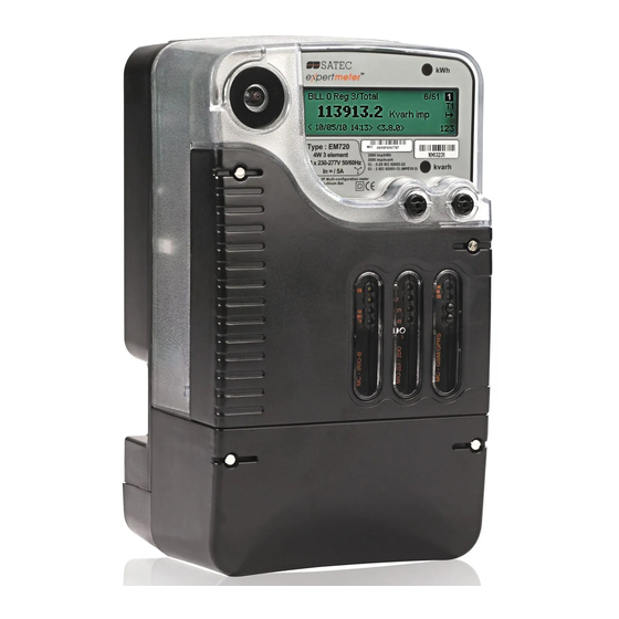
Satec expertmeter EM720 Installation Manual
Power quality and revenue meter
Hide thumbs
Also See for expertmeter EM720:
- Reference manual (149 pages) ,
- Operation manual (218 pages) ,
- Operation manual (216 pages)
Table of Contents
Advertisement
Quick Links
Advertisement
Table of Contents

Subscribe to Our Youtube Channel
Related Manuals for Satec expertmeter EM720


Summary of Contents for Satec expertmeter EM720
- Page 1 EM720 POWER QUALITY AND REVENUE METER Installation Manual BG0450 Rev. A4...
-
Page 2: Limited Warranty
LIMITED WARRANTY The manufacturer offers the customer a 24-month functional warranty on the instrument for faulty workmanship or parts from date of dispatch from the distributor. In all cases, this warranty is valid for 36 months from the date of production. This warranty is on a return to factory basis. The manufacturer does not accept liability for any damage caused by instrument malfunction. -
Page 3: Table Of Contents
Table of Contents Chapter 1 Introduction.................... 1 About This Manual......................1 About The EM720......................1 Chapter 2 Installation ..................... 3 Mechanical Installation ....................3 Electrical Installation ....................... 5 Primary electrical installation ....................5 Voltage Inputs...........................6 Current Inputs...........................6 Signal Ground Input........................6 Connectors location ........................6 Typical Installation ........................7 Wiring Configurations .......................8 Input / Output ports options.......................12... - Page 4 FIGURES Figure 1: Dimensions..........................3 Figure 2: Wall mount dimensions......................4 Figure 3: Memory Backup Lithium Battery and Battery Pack Installation ..........5 Figure 4: EM720 Connectors view ......................6 Figure 5: Typical Electrical Installation....................7 Figure 6: Three Wire Using 2 CTs - Wiring Setup: 3dir2 ..............8 Figure 7: Four Wire WYE Connection Using 3(4) CTs - Wiring Setup: 4LL3 or 4Ln3 ......9 Figure 8: Four Wire WYE Connection Using 3 PTs, 3 (4) CTs - Wiring Setup: 4LL3 or 4Ln3....9 Figure 9: Three Wire Open Delta Connection Using 2 PTs, 2 CTs - Wiring Setup: 3OP2 ....10...
-
Page 5: Chapter 1 Introduction
Chapter 1 Introduction About This Manual eXpertmeter™ POWER This manual is intended to assist the user in the installation of the EM720 QUALITY REVENUE METER Unit EM720’ . The term ‘ ’ is used herein to refer to all models in the series. EM720. - Page 6 A C / D C I n p u t s • Three AC voltage inputs - up to 480VAC direct line-to-line input voltage, for feeding and measurement • Three isolated AC voltage inputs - up to 2KV peak direct line-to-ground and neutral-to-ground input voltage •...
-
Page 7: Chapter 2 Installation
Chapter 2 Installation 1. Installation Mechanical Installation Refer to the figures provided in this section to properly perform the mechanical installation. F i g u r e 1 : D im e n s i o n s Chapter 2 Installation... -
Page 8: Figure 2: Wall Mount Dimensions
F i g u r e 2 : W a l l m o u n t d im e n s i o n s Chapter 2 Installation... -
Page 9: Electrical Installation
Electrical Installation Before installing, ensure that all incoming power sources are shut OFF. Failure to observe this practice can result in serious or even fatal injury and damage to equipment. Primary electrical installation EM720 EM720 Before connecting the to the power measurement terminals, remove the front cover, then install the memory backup Lithium Battery backup (MBB) and Battery Pack Backup Power Supply (BPS) F i g u r e 3 : M e m o r y B a c k u p L i t h i u m B a t t er y a n d B a t t e r y P a c k I n s t a l l a t i on... -
Page 10: Voltage Inputs
Voltage Inputs There are 3 AC Y-connected voltage inputs of 480V (phase-to-phase) and neutral, via Main Terminal Block. Copper wiring 2.5 – 6 mm2 (10 AWG) should be used. EM720 Power Supply Inputs are the same as the Voltages Inputs Current Inputs There are 4 current inputs up to 50A, connected to external CT’s via Main Terminal Block. -
Page 11: Typical Installation
Typical Installation Figure 5: Typical Electrical Installation Chapter 2 Installation... -
Page 12: Wiring Configurations
Wiring Configurations There are seven wiring configurations shown in Figures 6, 7, 8, 9, 10, 11, 12 or 13; W i r i n g C o n f i g u r a t i o n Wiring Setup See Figure: 3-wire 2-element direct connection using 2 CTs 3dir2... -
Page 13: Figure 7: Four Wire Wye Connection Using 3(4) Cts - Wiring Setup: 4Ll3 Or 4Ln3
F i g u r e 7 : F ou r W ir e W Y E C o n n e c t i on U s i n g 3 ( 4 ) C T s - W i r i n g S e t u p : 4 L L 3 o r 4 L n 3 F i g u r e 8 : F ou r W ir e W Y E C o n n e c t i on U s i n g 3 P T s , 3 ( 4) CT s - W i r i n g S e t u p : 4 L L 3 o r 4 L n 3 Chapter 2 Installation... -
Page 14: Figure 9: Three Wire Open Delta Connection Using 2 Pts, 2 Cts - Wiring Setup: 3Op2
F i g u r e 9 : T hr e e W i r e O pe n D e l t a C on n e c t i o n U s i n g 2 P T s , 2 C T s - W i r i n g S e t u p : 3 O P 2 F i g u r e 1 0 : T h r e e W i r e W y e C o n n e c t io n U s i n g 2 P T s , 3 CT s - W ir i n g S et u p : 3 L L 3 o r 3 L n 3 Energy is measured with 2 CTs only –... -
Page 15: Figure 11: Three Wire Open Delta Connection Using 2 Pts, 3 Cts - Wiring Setup: 3Op3
F i g u r e 1 1 : T h r e e W i r e O p e n D e l t a Co n n e c t i o n Us i n g 2 P T s , 3 C T s - W i r in g S e t u p : 3O P 3 Energy is measured with 2 CTs only –... -
Page 16: Input / Output Ports Options
Input / Output ports options O n b o ard D i gi t al Inp uts EM720 is equipped with four fast Dry contact detector – Digital Inputs unit. unit is terminated with a nine-pin width pluggable terminal block which connects eight terminals only –... -
Page 17: Figure 14: 2Di/2Do Connection
D ig it a l I n pu t s /D ig ita l O u tp u ts ( 2D I / 2D O – op t io n a l mod u le) 2D/2DO module consists of two status inputs and two FORM C relays outputs. 2D/2DO EM720 module can be plugged-in any... -
Page 18: Communications Options
Communications options EM720 has numerous communication possibilities depending on your ordering preferences. All communications ports, of different type, can be used simultaneously EM720 is equipped with one standard optical communication (COM) port. Other ports are available as optional module. In frar ed C ommun ica tio n po r t (COM1) Mount an optical probe cable (not included), at the instrument front panel, to communicate between the meter optical port and a PC serial port F i g u r e 1 5 : I n f r a r e d C o m m u n i c a t i o n p o r t –... -
Page 19: Figure 17: Serial Communication Network Connection – Rs-485 Com3
After one minute the "LNK" GREEN LED is flashing until it lights "ON" continuously The "RSSI" ORANGE LED will light "ON" or blinks, the flashing rate is proportional to the RF receive level (RSSI), if RF receive level is high then the led is "ON" continuously, if RF receive level is poor then the led is blinking R S- 48 5 /232 C o mm un ic a t ion por t ( C OM 3 –... -
Page 20: Figure 18: Serial Communication Connection – Rs-232 Com3
F i g u r e 1 8 : S e r i a l C o m m u n i c a t i o n C o n n e c t i o n – R S - 2 3 2 CO M 3 E T H E R N ET / U S B C om m un ic a t io n po r t ( ETH /U S B –... -
Page 21: Figure 20: Mini-Usb Device Connection
F i g u r e 2 0 : M i n i - U S B de v i c e C o n n e c t i o n To prevent potential differences between the Personal Computer (PC) USB port and the EM720 USB device port, it is recommended to use a galvanic isolated USB adaptor before connecting the EM720 USB port to a Personal Computer (PC), or to use battery powered PC. -
Page 22: Auxiliary Power Supply
Auxiliary Power Supply L ow D C A ux i lia r y Po w e r Sup p ly EM720 can be equipped with additional power supply to redundant the built-in power supply (Auxiliary Power Supply – ), without need of Battery backup Power Supply ( EM720 The DC can be plugged-in any... -
Page 23: Location Of Modules
Location of Modules EM720 The 3 slots expand the with additional input/output ports (future module), communication modules and Auxiliary DC Power Supply module. The following functions are available in the following slots: • IRIG-B – any slot • COM2 (Dial up or Cellular modem port) - slot 3 only •... -
Page 24: Chapter 3 Communications
Chapter 3 Communications 2. Communications Computer Connections – RS-232 F i g u r e 2 4 : RS - 2 3 2 S i m p l e 3 - w i r e C on n e c t i o n , 2 5 - p i n o r 9 - p i n P C C O M P o r t Computer Connections –... -
Page 25: Chapter 4 Replacing The Battery
Chapter 4 Replacing the Battery When the battery level drops below the minimum allowed threshold, the LCD graphic display, on the front of the device, shows: , indicating that the battery should be replaced. Use the following procedure: 1. Remove the sealed screw to open the front covers, as in figure 24 Remove the sealed screws to open Remove the sealed screws to open front covers to access the Battery... -
Page 26: Appendix: Technical Specifications
Appendix: Technical Specifications Inputs Ratings AC Voltage inputs V1, V2, V3, VN and VG 50/60 Hz Reference voltage Voltage rating: 57.73V up to 3 x 57.73/100 V 120V L-N (via PT) 3 x 63/110 V 3 x 69/120 V 3 x 57.73 V 3 x 63 V 3 x 69 V Voltage range,... - Page 27 AC Current inputs 4 Galvanic isolated Inputs Reference Current Overload current (continuously) Imax 2 x I Basic model Maximum measurable short circuit current ( Isc) 10 x I Burden per phase ( = 5 A) < 0.2 VA Option model = 1A Burden per phase =1 A)
-
Page 28: Power Supply
Power Supply 3P power supply Power Supply Inputs from measured AC Voltage inputs (MPS) 207-480V AC 50/60 Hz High range power supply (480V option) 96- 575V AC 100-120 V AC 50/60 Hz Low range power supply (120V option) 45 - 250 V AC Burden as per IEC 62053-61 multi-function meter 3 W and <15VA/phase requirements... -
Page 29: Communication Ports
Communication ports COM1 Front panel IR - Basic Optical Communication port IEC 62056-21 Max. Baud rate 19.200 kb/s Protocols Modbus RTU/ASCII and DNP3.0 COM2 Plug-in modules isolated communication port Field installable GSM/GPRS module Quad Band GPRS GSM/GPRS class10 module – Optional Max. -
Page 30: Console Display Unit
Console Display Unit Display LCD graphic bright display Multiple screens display Resolution 128 x 32 dots Viewing area 99.0 x 24.0 mm Operational temperature -20°C to + 70°C Backlit LCD display screen Timeout operation LEDs Active and reactive energy led pulses SCROLL Monitoring and configuring Sealed buttons SELECT/ENT... -
Page 31: Standards Compliance
Standards Compliance IEC standards IEC 61000-2 Immunity ESD - IEC61000-4-2/IEC 62052-11 15KV/– air/contact Electromagnetic RF Fields - IEC61000-4-3/IEC 30V/m @ 80Mhz – 62052-11 1000MHz FTB - IEC61000-4-4/IEC 62052-11 4KV on current and voltage circuits and 2 KV for auxiliary circuits SURGE - IEC61000-4-5/IEC 62052-11 4KV on current and voltage circuits and 1 KV... -
Page 32: Measurement Specifications
Measurement Specifications Full Scale @ Input Accuracy Parameter Range Range % Reading % FS Conditions Voltage V1-V3 230 x PT ratio @ 0.05 ±0.05 1% up to 140% 0 up to 999,000 V (L-n) 230V Voltage V4 230 x PT ratio @ ±0.5 5% up to 140% (calculated)
Need help?
Do you have a question about the expertmeter EM720 and is the answer not in the manual?
Questions and answers