Table of Contents
Advertisement
Quick Links
Advertisement
Table of Contents

Subscribe to Our Youtube Channel
Related Manuals for Satec Expertmeter Series


Summary of Contents for Satec Expertmeter Series
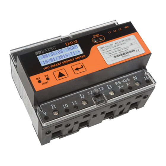
- Page 1 EM132-133 QUICK START GUIDE Quick Start Guide EM132-133 BG0504 REV.A2...
- Page 2 EM132-133 QUICK START GUIDE Mechanical Installation Figure 1: Instrument Dimensions BG0504 REV.A2...
-
Page 3: Mechanical Installation
EM132-133 QUICK START GUIDE Mechanical Installation Figure 2: Mounting the EM133 on DIN Rail or on flat surface IMPORTANT! Only qualified personnel can perform setup. All incoming power sources must be turned off during installation. During operation of the Powermeter, hazardous voltages are present on the input terminals. - Page 4 EM132-133 QUICK START GUIDE Typical Electrical Installation Figure 3:Common Wiring Mode: 4LL3 or 4Ln3 Wiring Configuration NOTE: Setup Code 3-wire 2-element Direct connection using 2 CTs 3dir2 Refer to the Installation and operation 4-wire Wye 3-element direct connection using 3 CTs 4Ln3 or 4LL3 manual for the wiring schematics 4-wire Wye 3-element connection using 3 PTs, 3 CTs...
-
Page 5: Electrical Installation
EM132-133 QUICK START GUIDE Electrical Installation Figure 4: CT Wiring options BG0504 REV.A2... -
Page 6: Module Installation
EM132-133 QUICK START GUIDE MODULE Installation This section applies to the I/O and Communication modules. MODULE 4 ANALOG OUT MODULE ETHERNET MODULE 4DI/2DO Figure 5: PM130 PLUS modules Module Connector Cover Remove Module Connector Cover before assembling module NOTE: Refer to the Installation and operation manual for the wiring schematics diagrams and setup parameters Module... -
Page 7: Basic Setup
EM132-133 QUICK START GUIDE Basic Setup All setups can be performed directly from the display panel or via communication ports using PAS communication software, except for Communications and Display setups, which must be performed directly at the instrument panel. To set the CT Primary current, perform the following steps: ... -
Page 8: Data Display
EM132-133 QUICK START GUIDE DATA DISPLAY Navigating in Display Mode The front panel has a simple interface that allows you to display numerous measurement parameters in up to 38 display pages. For easier reading, the parameters are divided into three groups; each group is accessible by pressing the key and each group page is accessible by pressing the The initial display is as described below:... -
Page 9: Basic Menu
EM132-133 QUICK START GUIDE Basic Menu Code Parameter Options Description ConF Wiring mode 3OP2 3-wire open delta using 2 CTs 4Ln3 4-wire Wye using 3 PTs (default) 3dir2 3-wire direct connection using 2 CTs 4LL3 4-wire Wye using 3 PTs 3OP3 3-wire open delta using 3 CTs 3Ln3... -
Page 10: Input And Output Ratings
EM132-133 QUICK START GUIDE Input and Output Ratings DIRECT INPUT - Nominal: 690V line-to-line voltage, 828V maximum; 57/98-400/690 VAC 400V line-to-neutral, 480V maximum - Burden: <0.5 VA. INPUT USING PT 3 voltage inputs - Burden: <0.15 VA Voltage input terminals 4 x Maximum wire section: 2.5 mm²...
Need help?
Do you have a question about the Expertmeter Series and is the answer not in the manual?
Questions and answers