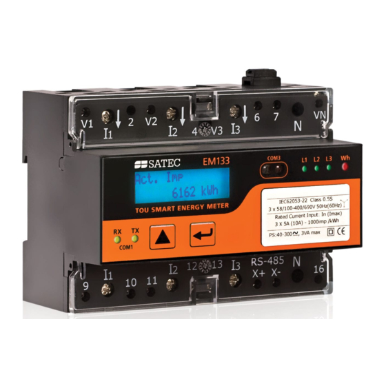
Satec EM133 Reference Manual
Multifunction meter
Hide thumbs
Also See for EM133:
- Installation and operation manual (169 pages) ,
- Quick start manual (11 pages)

Subscribe to Our Youtube Channel
Related Manuals for Satec EM133


Summary of Contents for Satec EM133
- Page 1 EM133 Multifunction Meter CANopen Communications Protocol Reference Guide BG0592 Rev. A1...
- Page 2 Every effort has been made to ensure that the material herein is complete and accurate. However, the manufacturer is not responsible for any mistakes in printing or faulty instructions contained in this book. Notification of any errors or misprints will be received with appreciation.
-
Page 3: Table Of Contents
Table of Contents 1 GENERAL......................5 2 CANOPEN PROTOCOL IMPLEMENTATION ............ 6 (EDS) F ..............6 OPEN LECTRONIC HEET ......................... 6 OPEN ERSION ........................... 6 ATES ........................6 DDRESS ....................6 NPUT AND UTPUT UFFERS ....................6 XTENDED IAGNOSTIC ......................6 OPEN AULT CTION... - Page 4 TOU Energy Register #2 ........................22 TOU Energy Register #3 ........................22 TOU Energy Register #4 ........................22 Billing Summary Accumulated Demands ..................... 22 Billing Summary Block Demands ......................23 Billing Summary Sliding Window Demands ..................23 Billing Summary Maximum Demands ....................23 TOU Maximum Demand Register #1 ....................
-
Page 5: General
1 General This document specifies the EM133 CANopen messaging protocol used to transfer data between a master CANopen station and the EM133. Refer to the EM133 Installation and Operation Manual for information on configuring communication parameters and electrical connections. IMPORTANT In 3-wire connection schemes, the unbalanced current and phase readings for power factor, active power, and reactive power will be zeros, because they have no meaning. -
Page 6: Canopen Protocol Implementation
The EM133 uses by default the CANopen protocol version 4. 2.3 Baud Rates The EM133 supports 20 kbps, 50 kbps, 125 kbps, 250 kbps, 500 kbps, 800 kbps and 1Mbps baud rates with automatic baud rate detection, so the actual baud rate is only configured in the CANopen master. -
Page 7: Canopen Messaging Protocol
2.8 CANopen Messaging Protocol Overview Since the EM133 transfer buffers only support 32 bytes or less transfer blocks, all of the device registers cannot possibly be sent over CANopen every scan. However, a messaging mechanism allows a master to access all the device registers by placing a command request pointing to the requested items in the output buffer and by receiving a corresponding response in the input buffer. - Page 8 In order to read seven data points in a double word format (32 bits), i.e. 14 words, starting with point 0x0C00 (V1-V3, I1-I3, kW L1, see section 3.1 below), from EM133 with CANopen Node ID = 126, the CANopen master writes a request as follows:...
-
Page 9: Device Response Block
The master should not concern the data in the device response block if this field contains an invalid code, or the exception field contains a non-zero value. The following table describes the mapping between TPDOs and data bytes sent by the EM133:... -
Page 10: Node Guarding
116.2V. TPDO2 Bytes 5-8 (V3): "0000048C" in hex, or 1164 decimal, so the actual V3 reading is 116.4V The other requested parameters are place in the EM133 transmited data as follows: TPDO3 Bytes 1-4: I1 TPDO3 Bytes 5-8: I2 TPDO4 Bytes 1-4: I3 TPDO4 Bytes 5-8: kW L1 The values of these parameters are calculated as showed for the phase voltages. -
Page 11: 16-Bit Scaled Analog Data
After the device restarts, the first time synchronization should be done by sending either a “Read” or “Clear” command. The “Write” commands sent immediately after the device restarts will be ignored until the CANopen link is synchronized. In order to provide reliable synchronous reads and writes in a natively asynchronous CANopen environment, it is recommended to follow a couple of simple rules: 1. - Page 12 Volts reading = (27245 – 0) (17,280 - 0)/(32767 – 0) + 0 = 14,368V 2. Current readings Assume device settings: CT primary current = 200A. Current engineering scales (see Section 4): ENG_HI = Imax = CT primary current 2 = 200.00 2 = 400.00A ENG_LO = 0A If the raw data reading is 819 then the current reading in engineering units will be as follows: Amps reading = (819 –...
-
Page 13: Device Register Map
3 Device Register Map 3.1 Analog Registers, Binary Registers and Counters Point Description Units Type Notes Options/Range 0x0000 None UINT16 Special Inputs 0x0101 Phase rotation order 0=error, 1=positive (ABC), UINT16 2=negative (CBA) 0x0600 Digital Inputs DI1-D2 0x0000-0x0003 UINT16 Bitmap: 0=open, 1=closed 0x0800 Relay Output RO1 0x0000-0x0001... -
Page 14: 1-Cycle Total Values
Point Description Units Type Notes Options/Range 0x0C14 V3/V31 Voltage THD 0-9999 0.1 UINT16 2-cycle value 0.1 0x0C15 I1 Current THD 0-9999 UINT16 2-cycle value 0.1 0x0C16 I2 Current THD 0-9999 UINT16 2-cycle value 0x0C17 I3 Current THD 0-9999 0.1 UINT16 2-cycle value 0x0C18 I1 K-Factor... -
Page 15: Phasor
Point Description Units Type Notes Options/Range 0x1003 Voltage unbalance 0-3000 0.1 UINT16 0.1 0x1004 Current unbalance 0-3000 UINT16 Phasor 0x1080 V1/V12 Voltage magnitude 0-Vmax UINT32 0x1081 V2/V23 Voltage magnitude 0-Vmax UINT32 0x1082 V3/V31 Voltage magnitude 0-Vmax UINT32 0x1083 Not used UINT32 0x1084 I1 Current magnitude... -
Page 16: 1-Second Total Values
Point Description Units Type Notes Options/Range 0x1111 Power factor L3 -1000-1000 0.00 INT16 0x1112 V1/V12 Voltage THD 0-9999 0.1 UINT16 3-sec value 0x1113 V2/V23 Voltage THD 0-9999 0.1 UINT16 3-sec value 0x1114 V3/V31 Voltage THD 0-9999 0.1 UINT16 3-sec value 0x1115 I1 Current THD 0-9999... -
Page 17: 1-Second Auxiliary Values
Point Description Units Type Notes Options/Range 0x140C 3-phase average current 0-Imax UINT32 1-Second Auxiliary Values 0x1500 Not used UINT32 0x1501 In (neutral) Current 0-Imax UINT32 0x1502 Frequency 0-Fmax 0.01 UINT16 0x1503 Voltage unbalance 0-3000 0.1 UINT16 0x1504 Current unbalance 0-3000 0.1 UINT16 Present Volt, Ampere and Power Demands... -
Page 18: Total Energies
Point Description Units Type Notes Options/Range 0x161E Not used UINT32 0x161F Not used UINT32 0x1620 Not used UINT32 0x1621 Not used UINT32 0x1622 In Ampere demand 0-Imax UINT32 Total Energies 0x1700 0-999,999,999 UINT32 kWh import 0x1701 kWh export 0-999,999,999 UINT32 0x1702 Not used INT32... -
Page 19: V2/V23 Harmonics
Point Description Units Type Notes Options/Range 0x1901 0-10000 0.01 UINT16 H02 Harmonic magnitude 0x1927 0-10000 0.01 UINT16 H40 Harmonic magnitude V2/V23 Harmonics 0x1A00 0-10000 0.01 UINT16 H01 Harmonic magnitude 0x1A01 0-10000 0.01 UINT16 H02 Harmonic magnitude 0x1A27 0-10000 0.01 UINT16 H40 Harmonic magnitude V3/V31 Harmonics 0x1B00... -
Page 20: Fundamental Phase Values
Point Description Units Type Notes Options/Range 0x1E27 0-10000 0.01 UINT16 H40 Harmonic magnitude Fundamental Phase Values 2-cycle values 0x2900 V1/V12 Voltage 0-Vmax UINT32 0x2901 V2/V23 Voltage 0-Vmax UINT32 0x2902 V3/V31 Voltage 0-Vmax UINT32 0x2903 I1 Current 0-Imax UINT32 0x2904 I2 Current 0-Imax UINT32 0x2905... -
Page 21: Minimum 1-Cycle Auxiliary Values
Point Description Units Type Notes Options/Range Minimum 1-Cycle Auxiliary Values 0x2E00 Not used UINT32 0x2E01 In Current 0-Imax UINT32 0x2E02 Frequency 0-Fmax 0.01 UINT32 Maximum 1-Cycle Phase Values 0x3400 V1/V12 Voltage 0-Vmax UINT32 0x3401 V2/V23 Voltage 0-Vmax UINT32 0x3402 V3/V31 Voltage 0-Vmax UINT32 0x3403... -
Page 22: Tou Parameters
Point Description Units Type Notes Options/Range 0x3711 Not used UINT32 0x3712 Not used UINT32 0x3713 Not used UINT32 0x3714 Not used UINT32 0x3715 In Maximum ampere demand 0-Imax UINT32 TOU Parameters 0x3C00 Active tariff UINT32 0x3C01 Active profile 0-15: UINT32 0-3 = Season 1 Profile #1-4, 4-7 = Season 2 Profile #1-4, 8-11 = Season 3 Profile #1-4,... -
Page 23: Billing Summary Block Demands
Point Description Units Type Notes Options/Range Billing Summary Block Demands 0x4580 0-Pmax UINT32 Summary register #1 demand 0x4581 0-Pmax UINT32 Summary register #2 demand 0x4582 0-Pmax UINT32 Summary register #3 demand 0x4583 0-Pmax UINT32 Summary register #4 demand Billing Summary Sliding Window Demands 0x4600 0-Pmax UINT32... -
Page 24: V2/V23 Harmonic Angles
Point Description Units Type Notes Options/Range 0x6427 -1800-1800 0.1º INT16 H40 Harmonic angle V2/V23 Harmonic Angles 1, 3 0.1º 0x6500 -1800-1800 INT16 H01 Harmonic angle 0.1º 0x6500 -1800-1800 INT16 H02 Harmonic angle 0x6527 -1800-1800 0.1º INT16 H40 Harmonic angle V1/V31 Harmonic Angles 1, 3 0x6600 -1800-1800... -
Page 25: Minimum/Maximum Log Registers
3.2 Minimum/Maximum Log Registers Point Description Type Notes Options/Range/Format Units Minimum Phase Values 0xB000 Min. V1/V12 Voltage 0-Vmax UINT32 0xB001 Timestamp UINT32 0xB002 Min. V2/V23 Voltage 0-Vmax UINT32 0xB003 Timestamp UINT32 0xB004 Min. V3/V31 Voltage 0-Vmax UINT32 0xB005 Timestamp UINT32 0xB006 Min. -
Page 26: Maximum Total Values
Point Description Type Notes Options/Range/Format Units 0xB209 Timestamp UINT32 0xB20A Max. I3 Current 0-Imax UINT32 0xB20B Timestamp UINT32 Maximum Total Values 0xB280 Max. Total kW -Pmax-Pmax INT32 0xB281 Timestamp UINT32 0xB282 Max. Total kvar -Pmax-Pmax INT32 0xB283 Timestamp UINT32 0xB284 Max. -
Page 27: Tou Maximum Demand Register #1
Point Description Type Notes Options/Range/Format Units 0xB38 UINT32 0xB38E Not used UINT32 0xB38F UINT32 0xB390 Not used UINT32 0xB391 UINT32 0xB392 Maximum kW import sliding window demand 0-Pmax UINT32 0xB393 Timestamp UINT32 0xB394 Maximum kvar import sliding window demand 0-Pmax UINT32 0xB395 Timestamp... -
Page 28: Tou Maximum Demand Register #3
Point Description Type Notes Options/Range/Format Units 0xB501 UINT32 Timestamp 0xB502 Tariff #2 maximum demand 0-Pmax UINT32 0xB503 UINT32 Timestamp … 0xB50E Tariff #8 maximum demand 0-Pmax UINT32 0xB50F UINT32 Timestamp TOU Maximum Demand Register #3 0xB580 Tariff #1 maximum demand 0-Pmax UINT32 0xB581... -
Page 29: Device Control And Status Registers
3.3 Device Control and Status Registers Point ID Description Options/Range Units Type Notes Device Reset/Clear Registers 0xA000 Clear total energy registers UINT Read as 0 0xA001 Clear total maximum demand registers 0 = Clear all maximum UINT demands 1 = Clear power demands 2 = Clear volt and ampere demands 0xA004... -
Page 30: Device Setup Registers
3.4 Device Setup Registers Address Description Options/Range Units Type Notes Factory Device Settings and Identification 0xFF40- 0xFF5B Device serial number 0-99999999 UINT Device model ID 13330 UINT +2-5 Device model name “EM133EH” UINT Null-terminated string Device options (bitmap) UINT Not used +7-9 Reserved UINT... -
Page 31: Communication Ports Setup
0.1A UINT Current scale, in secondary amps = CT secondary current (1A, 5A) Current overload Communication Ports Setup 0x8500- 0x851F Communication protocol COM1: 0=SATEC ASCII, UINT 1=Modbus RTU, 2=DNP3.0, 7= IEC 60870-5 COM2: 8=CANopen Interface COM1: 2=RS-485 UINT COM2: 10=CANopen... -
Page 32: Device Options Setup
Address Description Options/Range Units Type Notes PT ratio 10 to 65000 0.1 UINT CT primary current 1 to 10,000 UINT Power block demand period 1,2,3,5,10,15,20,30,60 min, UINT If the external synchronization is selected, 255 = external synchronization the DI1 input is considered a pulse or KYZ input. -
Page 33: Clock Setup
Address Description Options/Range Units Type Notes test Starting voltage, percent of FS voltage 15-50 0.1% UINT Default 1.5% +12-13 Reserved UINT Read as 65535 Device resolution (see Section 4 for details) 0 = Low resolution, 1 = High UINT Default 0 resolution Clock Setup Local time, in seconds, since Jan 1, 1970... -
Page 34: Data Scales And Units
4 Data Scales and Units Code Condition Value/Range Notes Data Scales Vmax Voltage scale PT Ratio, V Imax Current scale CT Ratio, A 1, 3 Pmax Wiring 4LN3, 3LN3, Vmax Imax 3, W 3BLN3 Wiring 4LL3, 3LL3, Vmax ... -
Page 35: Data Formats
5 Data Formats Format Value Description Notes Code Timestamp Local time in a UNIX-style format. Represents the 946684800 to number of seconds since midnight (00:00:00), 2145916799 January 1, 1970. The time is valid after January 1, allowed 2000. Wiring Mode 3OP2 - 3-wire open delta using 2 CTs (2 element) 4LN3 - 4-wire WYE using 3 PTs (3 element), line-to- neutral voltage readings... -
Page 37: Device Electronic Data Sheet (Eds) File
6 Device Electronic Data Sheet (EDS) File [FileInfo] FileName=EDS_ABIC_COP_V_1_01.eds FileVersion=1 FileRevision=00 Description=EDS file for the Anybus-IC CANopen module CreationTime=08:00PM CreationDate=06-23-2008 CreatedBy=Mikael Martensson, HMS Industrial Networks ModificationTime=08:22AM ModificationDate=04-14-2009 ModifiedBy=Joakim Wiberg, HMS Industrial Networks EDSVersion=4.0 [DeviceInfo] VendorName=HMS Industrial Networks ProductName=Anybus-IC BaudRate_10=0 BaudRate_20=1 BaudRate_50=1 BaudRate_125=1 BaudRate_250=1... - Page 38 NrOfTXPDO=24 LSS_Supported=1 [Comments] Lines=0x1 Line1=This is the EDS file for the Anybus-IC CANopen module [MandatoryObjects] SupportedObjects=3 1=0x1000 2=0x1001 3=0x1018 [1000] ParameterName=Device Type ObjectType=7 DataType=0x0007 LowLimit=0x0 HighLimit=0xFFFFFFFF AccessType=RO DefaultValue=0x0 PDOMapping=0 [1001] ParameterName=Error Register ObjectType=7 DataType=0x0005 AccessType=RO DefaultValue=0x0 PDOMapping=0 [1018] SubNumber=5 ParameterName=Identity Object ObjectType=9...
- Page 39 [1018sub0] ParameterName=Largest SubIndex supported ObjectType=7 DataType=0x0005 AccessType=RO DefaultValue=0x04 PDOMapping=0 LowLimit=0x04 HighLimit=0x04 [1018sub1] ParameterName=Vendor ID ObjectType=7 DataType=0x0007 AccessType=RO DefaultValue=0x1B PDOMapping=0 LowLimit=0x01 HighLimit=0xFFFFFFFF [1018sub2] ParameterName=Product Code ObjectType=7 DataType=0x0007 AccessType=RO DefaultValue=0x0B PDOMapping=0 LowLimit=0x01 HighLimit=0xFFFFFFFF [1018sub3] ParameterName=Revision ObjectType=7 DataType=0x0007 AccessType=RO PDOMapping=0...
- Page 40 DefaultValue=0x00010000 LowLimit=0x00000001 HighLimit=0xFFFFFFFF [1018sub4] ParameterName=Serial Number ObjectType=7 DataType=0x0007 AccessType=RO PDOMapping=0 LowLimit=0x00000001 HighLimit=0xFFFFFFFF [OptionalObjects] SupportedObjects=108 1=0x1003 2=0x1005 3=0x1008 4=0x100A 5=0x100C 6=0x100D 7=0x1010 8=0x1011 9=0x1014 10=0x1015 11=0x1016 12=0x1017 13=0x1400 14=0x1401 15=0x1402 16=0x1403 17=0x1404 18=0x1405 19=0x1406...
- Page 41 20=0x1407 21=0x1408 22=0x1409 23=0x140A 24=0x140B 25=0x140C 26=0x140D 27=0x140E 28=0x140F 29=0x1410 30=0x1411 31=0x1412 32=0x1413 33=0x1414 34=0x1415 35=0x1416 36=0x1417 37=0x1600 38=0x1601 39=0x1602 40=0x1603 41=0x1604 42=0x1605 43=0x1606 44=0x1607 45=0x1608 46=0x1609 47=0x160A 48=0x160B 49=0x160C 50=0x160D 51=0x160E 52=0x160F 53=0x1610 54=0x1611 55=0x1612...
- Page 42 56=0x1613 57=0x1614 58=0x1615 59=0x1616 60=0x1617 61=0x1800 62=0x1801 63=0x1802 64=0x1803 65=0x1804 66=0x1805 67=0x1806 68=0x1807 69=0x1808 70=0x1809 71=0x180A 72=0x180B 73=0x180C 74=0x180D 75=0x180E 76=0x180F 77=0x1810 78=0x1811 79=0x1812 80=0x1813 81=0x1814 82=0x1815 83=0x1816 84=0x1817 85=0x1A00 86=0x1A01 87=0x1A02 88=0x1A03 89=0x1A04 90=0x1A05 91=0x1A06...
- Page 43 92=0x1A07 93=0x1A08 94=0x1A09 95=0x1A0A 96=0x1A0B 97=0x1A0C 98=0x1A0D 99=0x1A0E 100=0x1A0F 101=0x1A10 102=0x1A11 103=0x1A12 104=0x1A13 105=0x1A14 106=0x1A15 107=0x1A16 108=0x1A17 [1003] SubNumber=6 ParameterName=Pre-Defined Error Field ObjectType=8 [1003sub0] ParameterName=Number of Errors ObjectType=7 DataType=0x0005 AccessType=RW DefaultValue=0 PDOMapping=0 LowLimit=0x00 HighLimit=0x05 [1003sub1] ParameterName=Standard Error-Field 1 ObjectType=7...
- Page 44 DataType=0x0007 AccessType=RO DefaultValue=0x0 PDOMapping=0 LowLimit=0 HighLimit=0xFFFFFFFF [1003sub2] ParameterName=Standard Error-Field 2 ObjectType=7 DataType=0x0007 AccessType=RO DefaultValue=0x0 PDOMapping=0 LowLimit=0 HighLimit=0xFFFFFFFF [1003sub3] ParameterName=Standard Error-Field 3 ObjectType=7 DataType=0x0007 AccessType=RO DefaultValue=0x0 PDOMapping=0 LowLimit=0 HighLimit=0xFFFFFFFF [1003sub4] ParameterName=Standard Error-Field 4 ObjectType=7 DataType=0x0007 AccessType=RO DefaultValue=0x0 PDOMapping=0 LowLimit=0 HighLimit=0xFFFFFFFF...
- Page 45 [1003sub5] ParameterName=Standard Error-Field 5 ObjectType=7 DataType=0x0007 AccessType=RO DefaultValue=0x0 PDOMapping=0 LowLimit=0 HighLimit=0xFFFFFFFF [1005] ParameterName=COBID Sync Message ObjectType=7 DataType=0x0007 LowLimit=0x00000001 HighLimit=0xFFFFFFFF DefaultValue=0x00000080 AccessType=rw PDOMapping=0 [1008] ParameterName=Manufacturer Device Name ObjectType=7 DataType=0x0009 AccessType=CONST DefaultValue=Anybus-IC PDOMapping=0 [100a] ParameterName=Software-Version ObjectType=7 DataType=0x0009 AccessType=CONST DefaultValue=1.00 PDOMapping=0...
- Page 46 [100c] ParameterName=Guard-Time ObjectType=7 DataType=0x0006 LowLimit=0x0000 HighLimit=0xFFFF AccessType=RW DefaultValue=0 PDOMapping=0 [100d] ParameterName=Life-Time Factor ObjectType=7 DataType=0x0005 LowLimit=0x00 HighLimit=0xFF AccessType=RW DefaultValue=0 PDOMapping=0 [1010] SubNumber=3 ParameterName=Store Parameters ObjectType=8 [1010sub0] ParameterName=Largest SubIndex supported ObjectType=7 DataType=0x0005 AccessType=RO DefaultValue=0x02 PDOMapping=0 LowLimit=0 HighLimit=0x02...
- Page 47 [1010sub1] ParameterName=Store all parameters ObjectType=7 DataType=0x0007 AccessType=RW PDOMapping=0 [1010sub2] ParameterName=Store Com parameters ObjectType=7 DataType=0x0007 AccessType=RW PDOMapping=0 [1011] SubNumber=3 ParameterName=Restore Parameters ObjectType=8 [1011sub0] ParameterName=Largest SubIndex supported ObjectType=7 DataType=0x0005 AccessType=RO DefaultValue=2 PDOMapping=0 LowLimit=0 HighLimit=0x02 [1011sub1] ParameterName=Restore all parameters ObjectType=7 DataType=0x0007 AccessType=RW PDOMapping=0...
- Page 48 [1011sub2] ParameterName=Restore com parameters ObjectType=7 DataType=0x0007 AccessType=RW PDOMapping=0 [1014] ParameterName=COBID Emergency Message ObjectType=7 DataType=0x0007 LowLimit=0x00000001 HighLimit=0xFFFFFFFF DefaultValue=$NODEID+0x80 AccessType=RO PDOMapping=0 [1015] ParameterName=Inhibit time EMCY ObjectType=7 DataType=0x0006 LowLimit=0x0000 HighLimit=0xFFFF AccessType=RW DefaultValue=0 PDOMapping=0 [1016] SubNumber=2 ParameterName=Consumer Heartbeat Time ObjectType=0x8 [1016sub0] ParameterName=Largest SubIndex supported ObjectType=7 DataType=0x0005...
- Page 49 LowLimit=1 HighLimit=0x7F DefaultValue=1 AccessType=RO PDOMapping=0 [1016sub1] ParameterName=Consumer Heartbeat Time ObjectType=7 DataType=0x0007 LowLimit=0x0 HighLimit=0x007FFFFF DefaultValue=0 AccessType=RW PDOMapping=0 [1017] ParameterName=Producer Heartbeat Time ObjectType=7 DataType=0x0006 LowLimit=0x0000 HighLimit=0xFFFF AccessType=RW DefaultValue=0 PDOMapping=0 ; Receive PDO parameters [1400] SubNumber=3 ParameterName=Receive PDO1 Parameter ObjectType=0x09 [1400sub0]...
- Page 50 ParameterName=Largest SubIndex supported ObjectType=7 DataType=0x0005 AccessType=RO LowLimit=2 HighLimit=2 DefaultValue=0x2 PDOMapping=0 [1400sub1] ParameterName=COBID ObjectType=7 DataType=0x0007 AccessType=RW PDOMapping=0 DefaultValue=$NODEID+0x200 [1400sub2] ParameterName=Transmission type ObjectType=7 DataType=0x0005 AccessType=RW DefaultValue=254 PDOMapping=0 [1401] SubNumber=3 ParameterName=Receive PDO2 Parameter ObjectType=0x09 [1401sub0] ParameterName=Largest SubIndex supported ObjectType=7 DataType=0x0005 AccessType=RO LowLimit=2...
- Page 51 HighLimit=2 DefaultValue=0x2 PDOMapping=0 [1401sub1] ParameterName=COBID ObjectType=7 DataType=0x0007 AccessType=RW PDOMapping=0 DefaultValue=$NODEID+0x300 [1401sub2] ParameterName=Transmission type ObjectType=7 DataType=0x0005 AccessType=RW DefaultValue=254 PDOMapping=0 [1402] SubNumber=3 ParameterName=Receive PDO3 Parameter ObjectType=0x09 [1402sub0] ParameterName=Largest SubIndex supported ObjectType=7 DataType=0x0005 AccessType=RO LowLimit=2 HighLimit=2 DefaultValue=0x2 PDOMapping=0 [1402sub1]...
- Page 52 ParameterName=COBID ObjectType=7 DataType=0x0007 AccessType=RW PDOMapping=0 DefaultValue=$NODEID+0x400 [1402sub2] ParameterName=Transmission type ObjectType=7 DataType=0x0005 AccessType=RW DefaultValue=254 PDOMapping=0 [1403] SubNumber=3 ParameterName=Receive PDO4 Parameter ObjectType=0x09 [1403sub0] ParameterName=Largest SubIndex supported ObjectType=7 DataType=0x0005 AccessType=RO LowLimit=2 HighLimit=2 DefaultValue=0x2 PDOMapping=0 [1403sub1] ParameterName=COBID ObjectType=7 DataType=0x0007 AccessType=RW PDOMapping=0...
- Page 53 DefaultValue=$NODEID+0x500 [1403sub2] ParameterName=Transmission type ObjectType=7 DataType=0x0005 AccessType=RW DefaultValue=254 PDOMapping=0 [1404] SubNumber=3 ParameterName=Receive PDO5 Parameter ObjectType=0x09 [1404sub0] ParameterName=Largest SubIndex supported ObjectType=7 DataType=0x0005 AccessType=RO LowLimit=2 HighLimit=2 DefaultValue=0x2 PDOMapping=0 [1404sub1] ParameterName=COBID ObjectType=7 DataType=0x0007 AccessType=RW PDOMapping=0 DefaultValue=$NODEID+0x80000240 [1404sub2] ParameterName=Transmission type ObjectType=7...
- Page 54 DataType=0x0005 AccessType=RW DefaultValue=254 PDOMapping=0 [1405] SubNumber=3 ParameterName=Receive PDO6 Parameter ObjectType=0x09 [1405sub0] ParameterName=Largest SubIndex supported ObjectType=7 DataType=0x0005 AccessType=RO LowLimit=2 HighLimit=2 DefaultValue=0x2 PDOMapping=0 [1405sub1] ParameterName=COBID ObjectType=7 DataType=0x0007 AccessType=RW PDOMapping=0 DefaultValue=$NODEID+0x80000340 [1405sub2] ParameterName=Transmission type ObjectType=7 DataType=0x0005 AccessType=RW DefaultValue=254 PDOMapping=0...
- Page 55 [1406] SubNumber=3 ParameterName=Receive PDO7 Parameter ObjectType=0x09 [1406sub0] ParameterName=Largest SubIndex supported ObjectType=7 DataType=0x0005 AccessType=RO LowLimit=2 HighLimit=2 DefaultValue=0x2 PDOMapping=0 [1406sub1] ParameterName=COBID ObjectType=7 DataType=0x0007 AccessType=RW PDOMapping=0 DefaultValue=$NODEID+0x80000440 [1406sub2] ParameterName=Transmission type ObjectType=7 DataType=0x0005 AccessType=RW DefaultValue=254 PDOMapping=0 [1407] SubNumber=3 ParameterName=Receive PDO8 Parameter ObjectType=0x09...
- Page 56 [1407sub0] ParameterName=Largest SubIndex supported ObjectType=7 DataType=0x0005 AccessType=RO LowLimit=2 HighLimit=2 DefaultValue=0x2 PDOMapping=0 [1407sub1] ParameterName=COBID ObjectType=7 DataType=0x0007 AccessType=RW PDOMapping=0 DefaultValue=$NODEID+0x80000540 [1407sub2] ParameterName=Transmission type ObjectType=7 DataType=0x0005 AccessType=RW DefaultValue=254 PDOMapping=0 [1408] SubNumber=3 ParameterName=Receive PDO9 Parameter ObjectType=0x09 [1408sub0] ParameterName=Largest SubIndex supported ObjectType=7 DataType=0x0005 AccessType=RO...
- Page 57 LowLimit=2 HighLimit=2 DefaultValue=0x2 PDOMapping=0 [1408sub1] ParameterName=COBID ObjectType=7 DataType=0x0007 AccessType=RW PDOMapping=0 DefaultValue=0x80000500 [1408sub2] ParameterName=Transmission type ObjectType=7 DataType=0x0005 AccessType=RW DefaultValue=254 PDOMapping=0 [1409] SubNumber=3 ParameterName=Receive PDO10 Parameter ObjectType=0x09 [1409sub0] ParameterName=Largest SubIndex supported ObjectType=7 DataType=0x0005 AccessType=RO LowLimit=2 HighLimit=2 DefaultValue=0x2 PDOMapping=0...
- Page 58 [1409sub1] ParameterName=COBID ObjectType=7 DataType=0x0007 AccessType=RW PDOMapping=0 DefaultValue=0x80000500 [1409sub2] ParameterName=Transmission type ObjectType=7 DataType=0x0005 AccessType=RW DefaultValue=254 PDOMapping=0 [140A] SubNumber=3 ParameterName=Receive PDO11 Parameter ObjectType=0x09 [140Asub0] ParameterName=Largest SubIndex supported ObjectType=7 DataType=0x0005 AccessType=RO LowLimit=2 HighLimit=2 DefaultValue=0x2 PDOMapping=0 [140Asub1] ParameterName=COBID ObjectType=7 DataType=0x0007 AccessType=RW...
- Page 59 PDOMapping=0 DefaultValue=0x80000500 [140Asub2] ParameterName=Transmission type ObjectType=7 DataType=0x0005 AccessType=RW DefaultValue=254 PDOMapping=0 [140B] SubNumber=3 ParameterName=Receive PDO12 Parameter ObjectType=0x09 [140Bsub0] ParameterName=Largest SubIndex supported ObjectType=7 DataType=0x0005 AccessType=RO LowLimit=2 HighLimit=2 DefaultValue=0x2 PDOMapping=0 [140Bsub1] ParameterName=COBID ObjectType=7 DataType=0x0007 AccessType=RW PDOMapping=0 DefaultValue=0x80000500 [140Bsub2] ParameterName=Transmission type...
- Page 60 ObjectType=7 DataType=0x0005 AccessType=RW DefaultValue=254 PDOMapping=0 [140C] SubNumber=3 ParameterName=Receive PDO13 Parameter ObjectType=0x09 [140Csub0] ParameterName=Largest SubIndex supported ObjectType=7 DataType=0x0005 AccessType=RO LowLimit=2 HighLimit=2 DefaultValue=0x2 PDOMapping=0 [140Csub1] ParameterName=COBID ObjectType=7 DataType=0x0007 AccessType=RW PDOMapping=0 DefaultValue=0x80000500 [140Csub2] ParameterName=Transmission type ObjectType=7 DataType=0x0005 AccessType=RW DefaultValue=254 PDOMapping=0...
- Page 61 [140D] SubNumber=3 ParameterName=Receive PDO14 Parameter ObjectType=0x09 [140Dsub0] ParameterName=Largest SubIndex supported ObjectType=7 DataType=0x0005 AccessType=RO LowLimit=2 HighLimit=2 DefaultValue=0x2 PDOMapping=0 [140Dsub1] ParameterName=COBID ObjectType=7 DataType=0x0007 AccessType=RW PDOMapping=0 DefaultValue=0x80000500 [140Dsub2] ParameterName=Transmission type ObjectType=7 DataType=0x0005 AccessType=RW DefaultValue=254 PDOMapping=0 [140E] SubNumber=3 ParameterName=Receive PDO15 Parameter ObjectType=0x09...
- Page 62 [140Esub0] ParameterName=Largest SubIndex supported ObjectType=7 DataType=0x0005 AccessType=RO LowLimit=2 HighLimit=2 DefaultValue=0x2 PDOMapping=0 [140Esub1] ParameterName=COBID ObjectType=7 DataType=0x0007 AccessType=RW PDOMapping=0 DefaultValue=0x80000500 [140Esub2] ParameterName=Transmission type ObjectType=7 DataType=0x0005 AccessType=RW DefaultValue=254 PDOMapping=0 [140F] SubNumber=3 ParameterName=Receive PDO16 Parameter ObjectType=0x09 [140Fsub0] ParameterName=Largest SubIndex supported ObjectType=7 DataType=0x0005...
- Page 63 AccessType=RO LowLimit=2 HighLimit=2 DefaultValue=0x2 PDOMapping=0 [140Fsub1] ParameterName=COBID ObjectType=7 DataType=0x0007 AccessType=RW PDOMapping=0 DefaultValue=0x80000500 [140Fsub2] ParameterName=Transmission type ObjectType=7 DataType=0x0005 AccessType=RW DefaultValue=254 PDOMapping=0 [1410] SubNumber=3 ParameterName=Receive PDO17 Parameter ObjectType=0x09 [1410sub0] ParameterName=Largest SubIndex supported ObjectType=7 DataType=0x0005 AccessType=RO LowLimit=2 HighLimit=2 DefaultValue=0x2 PDOMapping=0...
- Page 64 [1410sub1] ParameterName=COBID ObjectType=7 DataType=0x0007 AccessType=RW PDOMapping=0 DefaultValue=0x80000500 [1410sub2] ParameterName=Transmission type ObjectType=7 DataType=0x0005 AccessType=RW DefaultValue=254 PDOMapping=0 [1411] SubNumber=3 ParameterName=Receive PDO18 Parameter ObjectType=0x09 [1411sub0] ParameterName=Largest SubIndex supported ObjectType=7 DataType=0x0005 AccessType=RO LowLimit=2 HighLimit=2 DefaultValue=0x2 PDOMapping=0 [1411sub1] ParameterName=COBID ObjectType=7 DataType=0x0007...
- Page 65 AccessType=RW PDOMapping=0 DefaultValue=0x80000500 [1411sub2] ParameterName=Transmission type ObjectType=7 DataType=0x0005 AccessType=RW DefaultValue=254 PDOMapping=0 [1412] SubNumber=3 ParameterName=Receive PDO19 Parameter ObjectType=0x09 [1412sub0] ParameterName=Largest SubIndex supported ObjectType=7 DataType=0x0005 AccessType=RO LowLimit=2 HighLimit=2 DefaultValue=0x2 PDOMapping=0 [1412sub1] ParameterName=COBID ObjectType=7 DataType=0x0007 AccessType=RW PDOMapping=0 DefaultValue=0x80000500 [1412sub2]...
- Page 66 ParameterName=Transmission type ObjectType=7 DataType=0x0005 AccessType=RW DefaultValue=254 PDOMapping=0 [1413] SubNumber=3 ParameterName=Receive PDO20 Parameter ObjectType=0x09 [1413sub0] ParameterName=Largest SubIndex supported ObjectType=7 DataType=0x0005 AccessType=RO LowLimit=2 HighLimit=2 DefaultValue=0x2 PDOMapping=0 [1413sub1] ParameterName=COBID ObjectType=7 DataType=0x0007 AccessType=RW PDOMapping=0 DefaultValue=0x80000500 [1413sub2] ParameterName=Transmission type ObjectType=7 DataType=0x0005 AccessType=RW DefaultValue=254...
- Page 67 PDOMapping=0 [1414] SubNumber=3 ParameterName=Receive PDO21 Parameter ObjectType=0x09 [1414sub0] ParameterName=Largest SubIndex supported ObjectType=7 DataType=0x0005 AccessType=RO LowLimit=2 HighLimit=2 DefaultValue=0x2 PDOMapping=0 [1414sub1] ParameterName=COBID ObjectType=7 DataType=0x0007 AccessType=RW PDOMapping=0 DefaultValue=0x80000500 [1414sub2] ParameterName=Transmission type ObjectType=7 DataType=0x0005 AccessType=RW DefaultValue=254 PDOMapping=0 [1415] SubNumber=3 ParameterName=Receive PDO22 Parameter...
- Page 68 ObjectType=0x09 [1415sub0] ParameterName=Largest SubIndex supported ObjectType=7 DataType=0x0005 AccessType=RO LowLimit=2 HighLimit=2 DefaultValue=0x2 PDOMapping=0 [1415sub1] ParameterName=COBID ObjectType=7 DataType=0x0007 AccessType=RW PDOMapping=0 DefaultValue=0x80000500 [1415sub2] ParameterName=Transmission type ObjectType=7 DataType=0x0005 AccessType=RW DefaultValue=254 PDOMapping=0 [1416] SubNumber=3 ParameterName=Receive PDO23 Parameter ObjectType=0x09 [1416sub0] ParameterName=Largest SubIndex supported ObjectType=7...
- Page 69 DataType=0x0005 AccessType=RO LowLimit=2 HighLimit=2 DefaultValue=0x2 PDOMapping=0 [1416sub1] ParameterName=COBID ObjectType=7 DataType=0x0007 AccessType=RW PDOMapping=0 DefaultValue=0x80000500 [1416sub2] ParameterName=Transmission type ObjectType=7 DataType=0x0005 AccessType=RW DefaultValue=254 PDOMapping=0 [1417] SubNumber=3 ParameterName=Receive PDO24 Parameter ObjectType=0x09 [1417sub0] ParameterName=Largest SubIndex supported ObjectType=7 DataType=0x0005 AccessType=RO LowLimit=2 HighLimit=2 DefaultValue=0x2...
- Page 70 PDOMapping=0 [1417sub1] ParameterName=COBID ObjectType=7 DataType=0x0007 AccessType=RW PDOMapping=0 DefaultValue=0x80000500 [1417sub2] ParameterName=Transmission type ObjectType=7 DataType=0x0005 AccessType=RW DefaultValue=254 PDOMapping=0 ; Receive PDO mapping [1600] SubNumber=9 ParameterName=Receive Pdo 1 Mapping ObjectType=9 [1600sub0] ParameterName=Number of mapped objects ObjectType=7 DataType=0x0005 AccessType=rw DefaultValue=8 PDOMapping=0 LowLimit=0 HighLimit=8...
- Page 71 [1600sub1] ParameterName=1.mapped object ObjectType=7 DataType=0x0007 AccessType=rw DefaultValue=0x21000108 PDOMapping=0 [1600sub2] ParameterName=2.mapped object ObjectType=7 DataType=0x0007 AccessType=rw DefaultValue=0x21000208 PDOMapping=0 [1600sub3] ParameterName=3.mapped object ObjectType=7 DataType=0x0007 AccessType=rw DefaultValue=0x21000308 PDOMapping=0 [1600sub4] ParameterName=4.mapped object ObjectType=7 DataType=0x0007 AccessType=rw DefaultValue=0x21000408 PDOMapping=0 [1600sub5] ParameterName=5.mapped object ObjectType=7...
- Page 72 DataType=0x0007 AccessType=rw DefaultValue=0x21000508 PDOMapping=0 [1600sub6] ParameterName=6.mapped object ObjectType=7 DataType=0x0007 AccessType=rw DefaultValue=0x21000608 PDOMapping=0 [1600sub7] ParameterName=7.mapped object ObjectType=7 DataType=0x0007 AccessType=rw DefaultValue=0x21000708 PDOMapping=0 [1600sub8] ParameterName=8.mapped object ObjectType=7 DataType=0x0007 AccessType=rw DefaultValue=0x21000808 PDOMapping=0 [1601] SubNumber=9 ParameterName=Receive Pdo 2 Mapping ObjectType=9 [1601sub0] ParameterName=Number of mapped objects...
- Page 73 ObjectType=7 DataType=0x0005 AccessType=rw DefaultValue=8 PDOMapping=0 LowLimit=0 HighLimit=8 [1601sub1] ParameterName=1.mapped object ObjectType=7 DataType=0x0007 AccessType=rw DefaultValue=0x21000908 PDOMapping=0 [1601sub2] ParameterName=2.mapped object ObjectType=7 DataType=0x0007 AccessType=rw DefaultValue=0x21000A08 PDOMapping=0 [1601sub3] ParameterName=3.mapped object ObjectType=7 DataType=0x0007 AccessType=rw DefaultValue=0x21000B08 PDOMapping=0 [1601sub4] ParameterName=4.mapped object ObjectType=7 DataType=0x0007...
- Page 74 AccessType=rw DefaultValue=0x21000C08 PDOMapping=0 [1601sub5] ParameterName=5.mapped object ObjectType=7 DataType=0x0007 AccessType=rw DefaultValue=0x21000D08 PDOMapping=0 [1601sub6] ParameterName=6.mapped object ObjectType=7 DataType=0x0007 AccessType=rw DefaultValue=0x21000E08 PDOMapping=0 [1601sub7] ParameterName=7.mapped object ObjectType=7 DataType=0x0007 AccessType=rw DefaultValue=0x21000F08 PDOMapping=0 [1601sub8] ParameterName=8.mapped object ObjectType=7 DataType=0x0007 AccessType=rw DefaultValue=0x21001008 PDOMapping=0...
- Page 75 [1602] SubNumber=9 ParameterName=Receive Pdo 3 Mapping ObjectType=9 [1602sub0] ParameterName=Number of mapped objects ObjectType=7 DataType=0x0005 AccessType=RW DefaultValue=8 PDOMapping=0 LowLimit=0 HighLimit=8 [1602sub1] ParameterName=1.mapped object ObjectType=7 DataType=0x0007 AccessType=RW DefaultValue=0x21001108 PDOMapping=0 [1602sub2] ParameterName=2.mapped object ObjectType=7 DataType=0x0007 AccessType=RW DefaultValue=0x21001208 PDOMapping=0 [1602sub3] ParameterName=3.mapped object ObjectType=7 DataType=0x0007 AccessType=RW...
- Page 76 DefaultValue=0x21001308 PDOMapping=0 [1602sub4] ParameterName=4.mapped object ObjectType=7 DataType=0x0007 AccessType=RW DefaultValue=0x21001408 PDOMapping=0 [1602sub5] ParameterName=5.mapped object ObjectType=7 DataType=0x0007 AccessType=RW DefaultValue=0x21001508 PDOMapping=0 [1602sub6] ParameterName=6.mapped object ObjectType=7 DataType=0x0007 AccessType=RW DefaultValue=0x21001608 PDOMapping=0 [1602sub7] ParameterName=7.mapped object ObjectType=7 DataType=0x0007 AccessType=RW DefaultValue=0x21001708 PDOMapping=0 [1602sub8]...
- Page 77 ParameterName=8.mapped object ObjectType=7 DataType=0x0007 AccessType=RW DefaultValue=0x21001808 PDOMapping=0 [1603] SubNumber=9 ParameterName=Receive Pdo 4 Mapping ObjectType=9 [1603sub0] ParameterName=Number of mapped objects ObjectType=7 DataType=0x0005 AccessType=RW DefaultValue=8 PDOMapping=0 LowLimit=0 HighLimit=8 [1603sub1] ParameterName=1.mapped object ObjectType=7 DataType=0x0007 AccessType=RW DefaultValue=0x21001908 PDOMapping=0 [1603sub2] ParameterName=2.mapped object ObjectType=7 DataType=0x0007 AccessType=RW DefaultValue=0x21001A08...
- Page 78 PDOMapping=0 [1603sub3] ParameterName=3.mapped object ObjectType=7 DataType=0x0007 AccessType=RW DefaultValue=0x21001B08 PDOMapping=0 [1603sub4] ParameterName=4.mapped object ObjectType=7 DataType=0x0007 AccessType=RW DefaultValue=0x21001C08 PDOMapping=0 [1603sub5] ParameterName=5.mapped object ObjectType=7 DataType=0x0007 AccessType=RW DefaultValue=0x21001D08 PDOMapping=0 [1603sub6] ParameterName=6.mapped object ObjectType=7 DataType=0x0007 AccessType=RW DefaultValue=0x21001E08 PDOMapping=0 [1603sub7] ParameterName=7.mapped object...
- Page 79 ObjectType=7 DataType=0x0007 AccessType=RW DefaultValue=0x21001F08 PDOMapping=0 [1603sub8] ParameterName=8.mapped object ObjectType=7 DataType=0x0007 AccessType=RW DefaultValue=0x21002008 PDOMapping=0 [1604] SubNumber=9 ParameterName=Receive Pdo 5 Mapping ObjectType=9 [1604sub0] ParameterName=Number of mapped objects ObjectType=7 DataType=0x0005 AccessType=RW DefaultValue=8 PDOMapping=0 LowLimit=0 HighLimit=8 [1604sub1] ParameterName=1.mapped object ObjectType=7 DataType=0x0007 AccessType=RW DefaultValue=0x21002108 PDOMapping=0...
- Page 80 [1604sub2] ParameterName=2.mapped object ObjectType=7 DataType=0x0007 AccessType=RW DefaultValue=0x21002208 PDOMapping=0 [1604sub3] ParameterName=3.mapped object ObjectType=7 DataType=0x0007 AccessType=RW DefaultValue=0x21002308 PDOMapping=0 [1604sub4] ParameterName=4.mapped object ObjectType=7 DataType=0x0007 AccessType=RW DefaultValue=0x21002408 PDOMapping=0 [1604sub5] ParameterName=5.mapped object ObjectType=7 DataType=0x0007 AccessType=RW DefaultValue=0x21002508 PDOMapping=0 [1604sub6] ParameterName=6.mapped object ObjectType=7...
- Page 81 DataType=0x0007 AccessType=RW DefaultValue=0x21002608 PDOMapping=0 [1604sub7] ParameterName=7.mapped object ObjectType=7 DataType=0x0007 AccessType=RW DefaultValue=0x21002708 PDOMapping=0 [1604sub8] ParameterName=8.mapped object ObjectType=7 DataType=0x0007 AccessType=RW DefaultValue=0x21002808 PDOMapping=0 [1605] SubNumber=9 ParameterName=Receive Pdo 6 Mapping ObjectType=9 [1605sub0] ParameterName=Number of mapped objects ObjectType=7 DataType=0x0005 AccessType=RW DefaultValue=8 PDOMapping=0 LowLimit=0 HighLimit=8...
- Page 82 [1605sub1] ParameterName=1.mapped object ObjectType=7 DataType=0x0007 AccessType=RW DefaultValue=0x21002908 PDOMapping=0 [1605sub2] ParameterName=2.mapped object ObjectType=7 DataType=0x0007 AccessType=RW DefaultValue=0x21002A08 PDOMapping=0 [1605sub3] ParameterName=3.mapped object ObjectType=7 DataType=0x0007 AccessType=RW DefaultValue=0x21002B08 PDOMapping=0 [1605sub4] ParameterName=4.mapped object ObjectType=7 DataType=0x0007 AccessType=RW DefaultValue=0x21002C08 PDOMapping=0 [1605sub5] ParameterName=5.mapped object ObjectType=7 DataType=0x0007...
- Page 83 AccessType=RW DefaultValue=0x21002D08 PDOMapping=0 [1605sub6] ParameterName=6.mapped object ObjectType=7 DataType=0x0007 AccessType=RW DefaultValue=0x21002E08 PDOMapping=0 [1605sub7] ParameterName=7.mapped object ObjectType=7 DataType=0x0007 AccessType=RW DefaultValue=0x21002F08 PDOMapping=0 [1605sub8] ParameterName=8.mapped object ObjectType=7 DataType=0x0007 AccessType=RW DefaultValue=0x21003008 PDOMapping=0 [1606] SubNumber=9 ParameterName=Receive Pdo 7 Mapping ObjectType=9 [1606sub0] ParameterName=Number of mapped objects ObjectType=7...
- Page 84 DataType=0x0005 AccessType=RW DefaultValue=8 PDOMapping=0 LowLimit=0 HighLimit=8 [1606sub1] ParameterName=1.mapped object ObjectType=7 DataType=0x0007 AccessType=RW DefaultValue=0x21003108 PDOMapping=0 [1606sub2] ParameterName=2.mapped object ObjectType=7 DataType=0x0007 AccessType=RW DefaultValue=0x21003208 PDOMapping=0 [1606sub3] ParameterName=3.mapped object ObjectType=7 DataType=0x0007 AccessType=RW DefaultValue=0x21003308 PDOMapping=0 [1606sub4] ParameterName=4.mapped object ObjectType=7 DataType=0x0007 AccessType=RW...
- Page 85 DefaultValue=0x21003408 PDOMapping=0 [1606sub5] ParameterName=5.mapped object ObjectType=7 DataType=0x0007 AccessType=RW DefaultValue=0x21003508 PDOMapping=0 [1606sub6] ParameterName=6.mapped object ObjectType=7 DataType=0x0007 AccessType=RW DefaultValue=0x21003608 PDOMapping=0 [1606sub7] ParameterName=7.mapped object ObjectType=7 DataType=0x0007 AccessType=RW DefaultValue=0x21003708 PDOMapping=0 [1606sub8] ParameterName=8.mapped object ObjectType=7 DataType=0x0007 AccessType=RW DefaultValue=0x21003808 PDOMapping=0 [1607]...
- Page 86 SubNumber=9 ParameterName=Receive Pdo 8 Mapping ObjectType=9 [1607sub0] ParameterName=Number of mapped objects ObjectType=7 DataType=0x0005 AccessType=RW DefaultValue=8 PDOMapping=0 LowLimit=0 HighLimit=8 [1607sub1] ParameterName=1.mapped object ObjectType=7 DataType=0x0007 AccessType=RW DefaultValue=0x21003908 PDOMapping=0 [1607sub2] ParameterName=2.mapped object ObjectType=7 DataType=0x0007 AccessType=RW DefaultValue=0x21003A08 PDOMapping=0 [1607sub3] ParameterName=3.mapped object ObjectType=7 DataType=0x0007 AccessType=RW DefaultValue=0x21003B08...
- Page 87 PDOMapping=0 [1607sub4] ParameterName=4.mapped object ObjectType=7 DataType=0x0007 AccessType=RW DefaultValue=0x21003C08 PDOMapping=0 [1607sub5] ParameterName=5.mapped object ObjectType=7 DataType=0x0007 AccessType=RW DefaultValue=0x21003D08 PDOMapping=0 [1607sub6] ParameterName=6.mapped object ObjectType=7 DataType=0x0007 AccessType=RW DefaultValue=0x21003E08 PDOMapping=0 [1607sub7] ParameterName=7.mapped object ObjectType=7 DataType=0x0007 AccessType=RW DefaultValue=0x21003F08 PDOMapping=0 [1607sub8] ParameterName=8.mapped object...
- Page 88 ObjectType=7 DataType=0x0007 AccessType=RW DefaultValue=0x21004008 PDOMapping=0 [1608] SubNumber=9 ParameterName=Receive Pdo 9 Mapping ObjectType=9 [1608sub0] ParameterName=Number of mapped objects ObjectType=7 DataType=0x0005 AccessType=RW DefaultValue=8 PDOMapping=0 LowLimit=0 HighLimit=8 [1608sub1] ParameterName=1.mapped object ObjectType=7 DataType=0x0007 AccessType=RW DefaultValue=0x21004108 PDOMapping=0 [1608sub2] ParameterName=2.mapped object ObjectType=7 DataType=0x0007 AccessType=RW DefaultValue=0x21004208 PDOMapping=0...
- Page 89 [1608sub3] ParameterName=3.mapped object ObjectType=7 DataType=0x0007 AccessType=RW DefaultValue=0x21004308 PDOMapping=0 [1608sub4] ParameterName=4.mapped object ObjectType=7 DataType=0x0007 AccessType=RW DefaultValue=0x21004408 PDOMapping=0 [1608sub5] ParameterName=5.mapped object ObjectType=7 DataType=0x0007 AccessType=RW DefaultValue=0x21004508 PDOMapping=0 [1608sub6] ParameterName=6.mapped object ObjectType=7 DataType=0x0007 AccessType=RW DefaultValue=0x21004608 PDOMapping=0 [1608sub7] ParameterName=7.mapped object ObjectType=7...
- Page 90 DataType=0x0007 AccessType=RW DefaultValue=0x21004708 PDOMapping=0 [1608sub8] ParameterName=8.mapped object ObjectType=7 DataType=0x0007 AccessType=RW DefaultValue=0x21004808 PDOMapping=0 [1609] SubNumber=9 ParameterName=Receive Pdo 10 Mapping ObjectType=9 [1609sub0] ParameterName=Number of mapped objects ObjectType=7 DataType=0x0005 AccessType=RW DefaultValue=8 PDOMapping=0 LowLimit=0 HighLimit=8 [1609sub1] ParameterName=1.mapped object ObjectType=7 DataType=0x0007 AccessType=RW DefaultValue=0x21004908 PDOMapping=0...
- Page 91 [1609sub2] ParameterName=2.mapped object ObjectType=7 DataType=0x0007 AccessType=RW DefaultValue=0x21004A08 PDOMapping=0 [1609sub3] ParameterName=3.mapped object ObjectType=7 DataType=0x0007 AccessType=RW DefaultValue=0x21004B08 PDOMapping=0 [1609sub4] ParameterName=4.mapped object ObjectType=7 DataType=0x0007 AccessType=RW DefaultValue=0x21004C08 PDOMapping=0 [1609sub5] ParameterName=5.mapped object ObjectType=7 DataType=0x0007 AccessType=RW DefaultValue=0x21004D08 PDOMapping=0 [1609sub6] ParameterName=6.mapped object ObjectType=7 DataType=0x0007...
- Page 92 AccessType=RW DefaultValue=0x21004E08 PDOMapping=0 [1609sub7] ParameterName=7.mapped object ObjectType=7 DataType=0x0007 AccessType=RW DefaultValue=0x21004F08 PDOMapping=0 [1609sub8] ParameterName=8.mapped object ObjectType=7 DataType=0x0007 AccessType=RW DefaultValue=0x21005008 PDOMapping=0 [160A] SubNumber=9 ParameterName=Receive Pdo 11 Mapping ObjectType=9 [160Asub0] ParameterName=Number of mapped objects ObjectType=7 DataType=0x0005 AccessType=RW DefaultValue=8 PDOMapping=0 LowLimit=0 HighLimit=8 [160Asub1]...
- Page 93 ParameterName=1.mapped object ObjectType=7 DataType=0x0007 AccessType=RW DefaultValue=0x21005108 PDOMapping=0 [160Asub2] ParameterName=2.mapped object ObjectType=7 DataType=0x0007 AccessType=RW DefaultValue=0x21005208 PDOMapping=0 [160Asub3] ParameterName=3.mapped object ObjectType=7 DataType=0x0007 AccessType=RW DefaultValue=0x21005308 PDOMapping=0 [160Asub4] ParameterName=4.mapped object ObjectType=7 DataType=0x0007 AccessType=RW DefaultValue=0x21005408 PDOMapping=0 [160Asub5] ParameterName=5.mapped object ObjectType=7 DataType=0x0007 AccessType=RW...
- Page 94 DefaultValue=0x21005508 PDOMapping=0 [160Asub6] ParameterName=6.mapped object ObjectType=7 DataType=0x0007 AccessType=RW DefaultValue=0x21005608 PDOMapping=0 [160Asub7] ParameterName=7.mapped object ObjectType=7 DataType=0x0007 AccessType=RW DefaultValue=0x21005708 PDOMapping=0 [160Asub8] ParameterName=8.mapped object ObjectType=7 DataType=0x0007 AccessType=RW DefaultValue=0x21005808 PDOMapping=0 [160B] SubNumber=9 ParameterName=Receive Pdo 12 Mapping ObjectType=9 [160Bsub0] ParameterName=Number of mapped objects ObjectType=7 DataType=0x0005...
- Page 95 AccessType=RW DefaultValue=8 PDOMapping=0 LowLimit=0 HighLimit=8 [160Bsub1] ParameterName=1.mapped object ObjectType=7 DataType=0x0007 AccessType=RW DefaultValue=0x21005908 PDOMapping=0 [160Bsub2] ParameterName=2.mapped object ObjectType=7 DataType=0x0007 AccessType=RW DefaultValue=0x21005A08 PDOMapping=0 [160Bsub3] ParameterName=3.mapped object ObjectType=7 DataType=0x0007 AccessType=RW DefaultValue=0x21005B08 PDOMapping=0 [160Bsub4] ParameterName=4.mapped object ObjectType=7 DataType=0x0007 AccessType=RW DefaultValue=0x21005C08...
- Page 96 PDOMapping=0 [160Bsub5] ParameterName=5.mapped object ObjectType=7 DataType=0x0007 AccessType=RW DefaultValue=0x21005D08 PDOMapping=0 [160Bsub6] ParameterName=6.mapped object ObjectType=7 DataType=0x0007 AccessType=RW DefaultValue=0x21005E08 PDOMapping=0 [160Bsub7] ParameterName=7.mapped object ObjectType=7 DataType=0x0007 AccessType=RW DefaultValue=0x21005F08 PDOMapping=0 [160Bsub8] ParameterName=8.mapped object ObjectType=7 DataType=0x0007 AccessType=RW DefaultValue=0x21006008 PDOMapping=0 [160C] SubNumber=9...
- Page 97 ParameterName=Receive Pdo 13 Mapping ObjectType=9 [160Csub0] ParameterName=Number of mapped objects ObjectType=7 DataType=0x0005 AccessType=RW DefaultValue=8 PDOMapping=0 LowLimit=0 HighLimit=8 [160Csub1] ParameterName=1.mapped object ObjectType=7 DataType=0x0007 AccessType=RW DefaultValue=0x21006108 PDOMapping=0 [160Csub2] ParameterName=2.mapped object ObjectType=7 DataType=0x0007 AccessType=RW DefaultValue=0x21006208 PDOMapping=0 [160Csub3] ParameterName=3.mapped object ObjectType=7 DataType=0x0007 AccessType=RW DefaultValue=0x21006308 PDOMapping=0...
- Page 98 [160Csub4] ParameterName=4.mapped object ObjectType=7 DataType=0x0007 AccessType=RW DefaultValue=0x21006408 PDOMapping=0 [160Csub5] ParameterName=5.mapped object ObjectType=7 DataType=0x0007 AccessType=RW DefaultValue=0x21006508 PDOMapping=0 [160Csub6] ParameterName=6.mapped object ObjectType=7 DataType=0x0007 AccessType=RW DefaultValue=0x21006608 PDOMapping=0 [160Csub7] ParameterName=7.mapped object ObjectType=7 DataType=0x0007 AccessType=RW DefaultValue=0x21006708 PDOMapping=0 [160Csub8] ParameterName=8.mapped object ObjectType=7...
- Page 99 DataType=0x0007 AccessType=RW DefaultValue=0x21006808 PDOMapping=0 [160D] SubNumber=9 ParameterName=Receive Pdo 14 Mapping ObjectType=9 [160Dsub0] ParameterName=Number of mapped objects ObjectType=7 DataType=0x0005 AccessType=RW DefaultValue=8 PDOMapping=0 LowLimit=0 HighLimit=8 [160Dsub1] ParameterName=1.mapped object ObjectType=7 DataType=0x0007 AccessType=RW DefaultValue=0x21006908 PDOMapping=0 [160Dsub2] ParameterName=2.mapped object ObjectType=7 DataType=0x0007 AccessType=RW DefaultValue=0x21006A08 PDOMapping=0...
- Page 100 [160Dsub3] ParameterName=3.mapped object ObjectType=7 DataType=0x0007 AccessType=RW DefaultValue=0x21006B08 PDOMapping=0 [160Dsub4] ParameterName=4.mapped object ObjectType=7 DataType=0x0007 AccessType=RW DefaultValue=0x21006C08 PDOMapping=0 [160Dsub5] ParameterName=5.mapped object ObjectType=7 DataType=0x0007 AccessType=RW DefaultValue=0x21006D08 PDOMapping=0 [160Dsub6] ParameterName=6.mapped object ObjectType=7 DataType=0x0007 AccessType=RW DefaultValue=0x21006E08 PDOMapping=0 [160Dsub7] ParameterName=7.mapped object ObjectType=7 DataType=0x0007...
- Page 101 AccessType=RW DefaultValue=0x21006F08 PDOMapping=0 [160Dsub8] ParameterName=8.mapped object ObjectType=7 DataType=0x0007 AccessType=RW DefaultValue=0x21007008 PDOMapping=0 [160E] SubNumber=9 ParameterName=Receive Pdo 15 Mapping ObjectType=9 [160Esub0] ParameterName=Number of mapped objects ObjectType=7 DataType=0x0005 AccessType=RW DefaultValue=8 PDOMapping=0 LowLimit=0 HighLimit=8 [160Esub1] ParameterName=1.mapped object ObjectType=7 DataType=0x0007 AccessType=RW DefaultValue=0x21007108 PDOMapping=0 [160Esub2]...
- Page 102 ParameterName=2.mapped object ObjectType=7 DataType=0x0007 AccessType=RW DefaultValue=0x21007208 PDOMapping=0 [160Esub3] ParameterName=3.mapped object ObjectType=7 DataType=0x0007 AccessType=RW DefaultValue=0x21007308 PDOMapping=0 [160Esub4] ParameterName=4.mapped object ObjectType=7 DataType=0x0007 AccessType=RW DefaultValue=0x21007408 PDOMapping=0 [160Esub5] ParameterName=5.mapped object ObjectType=7 DataType=0x0007 AccessType=RW DefaultValue=0x21007508 PDOMapping=0 [160Esub6] ParameterName=6.mapped object ObjectType=7 DataType=0x0007 AccessType=RW...
- Page 103 DefaultValue=0x21007608 PDOMapping=0 [160Esub7] ParameterName=7.mapped object ObjectType=7 DataType=0x0007 AccessType=RW DefaultValue=0x21007708 PDOMapping=0 [160Esub8] ParameterName=8.mapped object ObjectType=7 DataType=0x0007 AccessType=RW DefaultValue=0x21007808 PDOMapping=0 [160F] SubNumber=9 ParameterName=Receive Pdo 16 Mapping ObjectType=9 [160Fsub0] ParameterName=Number of mapped objects ObjectType=7 DataType=0x0005 AccessType=RW DefaultValue=8 PDOMapping=0 LowLimit=0 HighLimit=8 [160Fsub1] ParameterName=1.mapped object...
- Page 104 ObjectType=7 DataType=0x0007 AccessType=RW DefaultValue=0x21007908 PDOMapping=0 [160Fsub2] ParameterName=2.mapped object ObjectType=7 DataType=0x0007 AccessType=RW DefaultValue=0x21007A08 PDOMapping=0 [160Fsub3] ParameterName=3.mapped object ObjectType=7 DataType=0x0007 AccessType=RW DefaultValue=0x21007B08 PDOMapping=0 [160Fsub4] ParameterName=4.mapped object ObjectType=7 DataType=0x0007 AccessType=RW DefaultValue=0x21007C08 PDOMapping=0 [160Fsub5] ParameterName=5.mapped object ObjectType=7 DataType=0x0007 AccessType=RW DefaultValue=0x21007D08...
- Page 105 PDOMapping=0 [160Fsub6] ParameterName=6.mapped object ObjectType=7 DataType=0x0007 AccessType=RW DefaultValue=0x21007E08 PDOMapping=0 [160Fsub7] ParameterName=7.mapped object ObjectType=7 DataType=0x0007 AccessType=RW DefaultValue=0x21007F08 PDOMapping=0 [160Fsub8] ParameterName=8.mapped object ObjectType=7 DataType=0x0007 AccessType=RW DefaultValue=0x21008008 PDOMapping=0 [1610] SubNumber=9 ParameterName=Receive Pdo 17 Mapping ObjectType=9 [1610sub0] ParameterName=Number of mapped objects ObjectType=7 DataType=0x0005 AccessType=RW...
- Page 106 DefaultValue=8 PDOMapping=0 LowLimit=0 HighLimit=8 [1610sub1] ParameterName=1.mapped object ObjectType=7 DataType=0x0007 AccessType=RW DefaultValue=0x21010108 PDOMapping=0 [1610sub2] ParameterName=2.mapped object ObjectType=7 DataType=0x0007 AccessType=RW DefaultValue=0x21010208 PDOMapping=0 [1610sub3] ParameterName=3.mapped object ObjectType=7 DataType=0x0007 AccessType=RW DefaultValue=0x21010308 PDOMapping=0 [1610sub4] ParameterName=4.mapped object ObjectType=7 DataType=0x0007 AccessType=RW DefaultValue=0x21010408 PDOMapping=0...
- Page 107 [1610sub5] ParameterName=5.mapped object ObjectType=7 DataType=0x0007 AccessType=RW DefaultValue=0x21010508 PDOMapping=0 [1610sub6] ParameterName=6.mapped object ObjectType=7 DataType=0x0007 AccessType=RW DefaultValue=0x21010608 PDOMapping=0 [1610sub7] ParameterName=7.mapped object ObjectType=7 DataType=0x0007 AccessType=RW DefaultValue=0x21010708 PDOMapping=0 [1610sub8] ParameterName=8.mapped object ObjectType=7 DataType=0x0007 AccessType=RW DefaultValue=0x21010808 PDOMapping=0 [1611] SubNumber=9 ParameterName=Receive Pdo 18 Mapping...
- Page 108 ObjectType=9 [1611sub0] ParameterName=Number of mapped objects ObjectType=7 DataType=0x0005 AccessType=RW DefaultValue=8 PDOMapping=0 LowLimit=0 HighLimit=8 [1611sub1] ParameterName=1.mapped object ObjectType=7 DataType=0x0007 AccessType=RW DefaultValue=0x21010908 PDOMapping=0 [1611sub2] ParameterName=2.mapped object ObjectType=7 DataType=0x0007 AccessType=RW DefaultValue=0x21010A08 PDOMapping=0 [1611sub3] ParameterName=3.mapped object ObjectType=7 DataType=0x0007 AccessType=RW DefaultValue=0x21010B08 PDOMapping=0...
- Page 109 [1611sub4] ParameterName=4.mapped object ObjectType=7 DataType=0x0007 AccessType=RW DefaultValue=0x21010C08 PDOMapping=0 [1611sub5] ParameterName=5.mapped object ObjectType=7 DataType=0x0007 AccessType=RW DefaultValue=0x21010D08 PDOMapping=0 [1611sub6] ParameterName=6.mapped object ObjectType=7 DataType=0x0007 AccessType=RW DefaultValue=0x21010E08 PDOMapping=0 [1611sub7] ParameterName=7.mapped object ObjectType=7 DataType=0x0007 AccessType=RW DefaultValue=0x21010F08 PDOMapping=0 [1611sub8] ParameterName=8.mapped object ObjectType=7 DataType=0x0007...
- Page 110 AccessType=RW DefaultValue=0x21011008 PDOMapping=0 [1612] SubNumber=9 ParameterName=Receive Pdo 19 Mapping ObjectType=9 [1612sub0] ParameterName=Number of mapped objects ObjectType=7 DataType=0x0005 AccessType=RW DefaultValue=0 PDOMapping=0 LowLimit=0 HighLimit=8 [1612sub1] ParameterName=1.mapped object ObjectType=7 DataType=0x0007 DefaultValue=0x21100110 AccessType=RW PDOMapping=0 [1612sub2] ParameterName=2.mapped object ObjectType=7 DataType=0x0007 DefaultValue=0x21100210 AccessType=RW PDOMapping=0 [1612sub3]...
- Page 111 ParameterName=3.mapped object ObjectType=7 DataType=0x0007 DefaultValue=0x21100310 AccessType=RW PDOMapping=0 [1612sub4] ParameterName=4.mapped object ObjectType=7 DataType=0x0007 DefaultValue=0x21100410 AccessType=RW PDOMapping=0 [1612sub5] ParameterName=5.mapped object ObjectType=7 DataType=0x0007 DefaultValue=0x00050008 AccessType=RW PDOMapping=0 [1612sub6] ParameterName=6.mapped object ObjectType=7 DataType=0x0007 DefaultValue=0x00050008 AccessType=RW PDOMapping=0 [1612sub7] ParameterName=7.mapped object ObjectType=7 DataType=0x0007 DefaultValue=0x00050008...
- Page 112 AccessType=RW PDOMapping=0 [1612sub8] ParameterName=8.mapped object ObjectType=7 DataType=0x0007 DefaultValue=0x00050008 AccessType=RW PDOMapping=0 [1613] SubNumber=9 ParameterName=Receive Pdo 20 Mapping ObjectType=9 [1613sub0] ParameterName=Number of mapped objects ObjectType=7 DataType=0x0005 AccessType=RW DefaultValue=0 PDOMapping=0 LowLimit=0 HighLimit=8 [1613sub1] ParameterName=1.mapped object ObjectType=7 DataType=0x0007 AccessType=RW DefaultValue=0x21100510 PDOMapping=0 [1613sub2] ParameterName=2.mapped object...
- Page 113 ObjectType=7 DataType=0x0007 AccessType=RW DefaultValue=0x21100610 PDOMapping=0 [1613sub3] ParameterName=3.mapped object ObjectType=7 DataType=0x0007 AccessType=RW DefaultValue=0x21100710 PDOMapping=0 [1613sub4] ParameterName=4.mapped object ObjectType=7 DataType=0x0007 AccessType=RW DefaultValue=0x21100810 PDOMapping=0 [1613sub5] ParameterName=5.mapped object ObjectType=7 DataType=0x0007 DefaultValue=0x00050008 AccessType=RW PDOMapping=0 [1613sub6] ParameterName=6.mapped object ObjectType=7 DataType=0x0007 DefaultValue=0x00050008 AccessType=RW...
- Page 114 PDOMapping=0 [1613sub7] ParameterName=7.mapped object ObjectType=7 DataType=0x0007 DefaultValue=0x00050008 AccessType=RW PDOMapping=0 [1613sub8] ParameterName=8.mapped object ObjectType=7 DataType=0x0007 DefaultValue=0x00050008 AccessType=RW PDOMapping=0 [1614] SubNumber=9 ParameterName=Receive Pdo 21 Mapping ObjectType=9 [1614sub0] ParameterName=Number of mapped objects ObjectType=7 DataType=0x0005 AccessType=RW DefaultValue=0 PDOMapping=0 LowLimit=0 HighLimit=8 [1614sub1] ParameterName=1.mapped object ObjectType=7...
- Page 115 DataType=0x0007 AccessType=RW DefaultValue=0x21100910 PDOMapping=0 [1614sub2] ParameterName=2.mapped object ObjectType=7 DataType=0x0007 AccessType=RW DefaultValue=0x21100A10 PDOMapping=0 [1614sub3] ParameterName=3.mapped object ObjectType=7 DataType=0x0007 AccessType=RW DefaultValue=0x21100B10 PDOMapping=0 [1614sub4] ParameterName=4.mapped object ObjectType=7 DataType=0x0007 AccessType=RW DefaultValue=0x21100C10 PDOMapping=0 [1614sub5] ParameterName=5.mapped object ObjectType=7 DataType=0x0007 AccessType=RW DefaultValue=0x00050008 PDOMapping=0...
- Page 116 [1614sub6] ParameterName=6.mapped object ObjectType=7 DataType=0x0007 AccessType=RW DefaultValue=0x00050008 PDOMapping=0 [1614sub7] ParameterName=7.mapped object ObjectType=7 DataType=0x0007 AccessType=RW DefaultValue=0x00050008 PDOMapping=0 [1614sub8] ParameterName=8.mapped object ObjectType=7 DataType=0x0007 AccessType=RW DefaultValue=0x00050008 PDOMapping=0 [1615] SubNumber=9 ParameterName=Receive Pdo 22 Mapping ObjectType=9 [1615sub0] ParameterName=Number of mapped objects ObjectType=7 DataType=0x0005 AccessType=RW DefaultValue=0...
- Page 117 PDOMapping=0 LowLimit=0 HighLimit=8 [1615sub1] ParameterName=1.mapped object ObjectType=7 DataType=0x0007 AccessType=RW DefaultValue=0x21100D10 PDOMapping=0 [1615sub2] ParameterName=2.mapped object ObjectType=7 DataType=0x0007 AccessType=RW DefaultValue=0x21100E10 PDOMapping=0 [1615sub3] ParameterName=3.mapped object ObjectType=7 DataType=0x0007 AccessType=RW DefaultValue=0x21100F10 PDOMapping=0 [1615sub4] ParameterName=4.mapped object ObjectType=7 DataType=0x0007 AccessType=RW DefaultValue=0x21101010 PDOMapping=0...
- Page 118 [1615sub5] ParameterName=5.mapped object ObjectType=7 DataType=0x0007 AccessType=RW DefaultValue=0x00050008 PDOMapping=0 [1615sub6] ParameterName=6.mapped object ObjectType=7 DataType=0x0007 AccessType=RW DefaultValue=0x00050008 PDOMapping=0 [1615sub7] ParameterName=7.mapped object ObjectType=7 DataType=0x0007 AccessType=RW DefaultValue=0x00050008 PDOMapping=0 [1615sub8] ParameterName=8.mapped object ObjectType=7 DataType=0x0007 AccessType=RW DefaultValue=0x00050008 PDOMapping=0 [1616] SubNumber=9 ParameterName=Receive Pdo 23 Mapping ObjectType=9...
- Page 119 [1616sub0] ParameterName=Number of mapped objects ObjectType=7 DataType=0x0005 AccessType=RW DefaultValue=0 PDOMapping=0 LowLimit=0 HighLimit=8 [1616sub1] ParameterName=1.mapped object ObjectType=7 DataType=0x0007 AccessType=RW DefaultValue=0x21101110 PDOMapping=0 [1616sub2] ParameterName=2.mapped object ObjectType=7 DataType=0x0007 AccessType=RW DefaultValue=0x21101210 PDOMapping=0 [1616sub3] ParameterName=3.mapped object ObjectType=7 DataType=0x0007 AccessType=RW DefaultValue=0x21101310 PDOMapping=0 [1616sub4]...
- Page 120 ParameterName=4.mapped object ObjectType=7 DataType=0x0007 AccessType=RW DefaultValue=0x21101410 PDOMapping=0 [1616sub5] ParameterName=5.mapped object ObjectType=7 DataType=0x0007 AccessType=RW DefaultValue=0x00050008 PDOMapping=0 [1616sub6] ParameterName=6.mapped object ObjectType=7 DataType=0x0007 AccessType=RW DefaultValue=0x00050008 PDOMapping=0 [1616sub7] ParameterName=7.mapped object ObjectType=7 DataType=0x0007 AccessType=RW DefaultValue=0x00050008 PDOMapping=0 [1616sub8] ParameterName=8.mapped object ObjectType=7 DataType=0x0007 AccessType=RW...
- Page 121 DefaultValue=0x00050008 PDOMapping=0 [1617] SubNumber=9 ParameterName=Receive Pdo 24 Mapping ObjectType=9 [1617sub0] ParameterName=Number of mapped objects ObjectType=7 DataType=0x0005 AccessType=RW DefaultValue=0 PDOMapping=0 LowLimit=0 HighLimit=8 [1617sub1] ParameterName=1.mapped object ObjectType=7 DataType=0x0007 AccessType=RW DefaultValue=0x21101510 PDOMapping=0 [1617sub2] ParameterName=2.mapped object ObjectType=7 DataType=0x0007 AccessType=RW DefaultValue=0x21101610 PDOMapping=0 [1617sub3] ParameterName=3.mapped object...
- Page 122 ObjectType=7 DataType=0x0007 AccessType=RW DefaultValue=0x21101710 PDOMapping=0 [1617sub4] ParameterName=4.mapped object ObjectType=7 DataType=0x0007 AccessType=RW DefaultValue=0x21101810 PDOMapping=0 [1617sub5] ParameterName=5.mapped object ObjectType=7 DataType=0x0007 AccessType=RW DefaultValue=0x00050008 PDOMapping=0 [1617sub6] ParameterName=6.mapped object ObjectType=7 DataType=0x0007 AccessType=RW DefaultValue=0x00050008 PDOMapping=0 [1617sub7] ParameterName=7.mapped object ObjectType=7 DataType=0x0007 AccessType=RW DefaultValue=0x00050008...
- Page 123 PDOMapping=0 [1617sub8] ParameterName=8.mapped object ObjectType=7 DataType=0x0007 AccessType=RW DefaultValue=0x00050008 PDOMapping=0 ; Transmit PDO parameters [1800] SubNumber=5 ParameterName=Transmit PDO1 Parameter ObjectType=0x09 [1800sub0] ParameterName=Largest SubIndex supported ObjectType=7 DataType=0x0005 AccessType=RO LowLimit=2 HighLimit=5 DefaultValue=0x5 PDOMapping=0 [1800sub1] ParameterName=COBID ObjectType=7 DataType=0x0007 AccessType=RW PDOMapping=0 DefaultValue=$NODEID+0x180...
- Page 124 [1800sub2] ParameterName=Transmission type ObjectType=7 DataType=0x0005 AccessType=RW DefaultValue=254 PDOMapping=0 [1800sub3] ParameterName=Inhibit Time ObjectType=7 DataType=6 AccessType=RW DefaultValue=0 PDOMapping=0 [1800sub5] ParameterName=Event Timer ObjectType=7 DataType=0x0006 LowLimit=0x0 HighLimit=0xFFFF DefaultValue=0 AccessType=rw PDOMapping=0 [1801] SubNumber=5 ParameterName=Transmit PDO2 Parameter ObjectType=0x09 [1801sub0] ParameterName=Largest SubIndex supported ObjectType=7 DataType=0x0005...
- Page 125 AccessType=RO LowLimit=2 HighLimit=5 DefaultValue=0x5 PDOMapping=0 [1801sub1] ParameterName=COBID ObjectType=7 DataType=0x0007 AccessType=RW PDOMapping=0 DefaultValue=$NODEID+0x280 [1801sub2] ParameterName=Transmission type ObjectType=7 DataType=0x0005 AccessType=RW DefaultValue=254 PDOMapping=0 [1801sub3] ParameterName=Inhibit Time ObjectType=7 DataType=6 AccessType=RW DefaultValue=0 PDOMapping=0 [1801sub5] ParameterName=Event Timer ObjectType=7 DataType=0x0006 LowLimit=0x0 HighLimit=0xFFFF...
- Page 126 DefaultValue=0 AccessType=rw PDOMapping=0 [1802] SubNumber=5 ParameterName=Transmit PDO3 Parameter ObjectType=0x09 [1802sub0] ParameterName=Largest SubIndex supported ObjectType=7 DataType=0x0005 AccessType=RO LowLimit=2 HighLimit=5 DefaultValue=0x5 PDOMapping=0 [1802sub1] ParameterName=COBID ObjectType=7 DataType=0x0007 AccessType=RW PDOMapping=0 DefaultValue=$NODEID+0x380 [1802sub2] ParameterName=Transmission type ObjectType=7 DataType=0x0005 AccessType=RW DefaultValue=254 PDOMapping=0 [1802sub3]...
- Page 127 ParameterName=Inhibit Time ObjectType=7 DataType=6 AccessType=RW DefaultValue=0 PDOMapping=0 [1802sub5] ParameterName=Event Timer ObjectType=7 DataType=0x0006 LowLimit=0x0 HighLimit=0xFFFF DefaultValue=0 AccessType=rw PDOMapping=0 [1803] SubNumber=5 ParameterName=Transmit PDO4 Parameter ObjectType=0x09 [1803sub0] ParameterName=Largest SubIndex supported ObjectType=7 DataType=0x0005 AccessType=RO LowLimit=2 HighLimit=5 DefaultValue=0x5 PDOMapping=0 [1803sub1] ParameterName=COBID ObjectType=7 DataType=0x0007...
- Page 128 AccessType=RW PDOMapping=0 DefaultValue=$NODEID+0x480 [1803sub2] ParameterName=Transmission type ObjectType=7 DataType=0x0005 AccessType=RW DefaultValue=254 PDOMapping=0 [1803sub3] ParameterName=Inhibit Time ObjectType=7 DataType=6 AccessType=RW DefaultValue=0 PDOMapping=0 [1803sub5] ParameterName=Event Timer ObjectType=7 DataType=0x0006 LowLimit=0x0 HighLimit=0xFFFF DefaultValue=0 AccessType=rw PDOMapping=0 [1804] SubNumber=5 ParameterName=Transmit PDO5 Parameter ObjectType=0x09 [1804sub0]...
- Page 129 ParameterName=Largest SubIndex supported ObjectType=7 DataType=0x0005 AccessType=RO LowLimit=2 HighLimit=5 DefaultValue=0x5 PDOMapping=0 [1804sub1] ParameterName=COBID ObjectType=7 DataType=0x0007 AccessType=RW PDOMapping=0 DefaultValue=$NODEID+0x800001C0 [1804sub2] ParameterName=Transmission type ObjectType=7 DataType=0x0005 AccessType=RW DefaultValue=254 PDOMapping=0 [1804sub3] ParameterName=Inhibit Time ObjectType=7 DataType=6 AccessType=RW DefaultValue=0 PDOMapping=0 [1804sub5] ParameterName=Event Timer ObjectType=7...
- Page 130 DataType=0x0006 LowLimit=0x0 HighLimit=0xFFFF DefaultValue=0 AccessType=rw PDOMapping=0 [1805] SubNumber=5 ParameterName=Transmit PDO6 Parameter ObjectType=0x09 [1805sub0] ParameterName=Largest SubIndex supported ObjectType=7 DataType=0x0005 AccessType=RO LowLimit=2 HighLimit=5 DefaultValue=0x5 PDOMapping=0 [1805sub1] ParameterName=COBID ObjectType=7 DataType=0x0007 AccessType=RW PDOMapping=0 DefaultValue=$NODEID+0x800002C0 [1805sub2] ParameterName=Transmission type ObjectType=7 DataType=0x0005 AccessType=RW DefaultValue=254...
- Page 131 PDOMapping=0 [1805sub3] ParameterName=Inhibit Time ObjectType=7 DataType=6 AccessType=RW DefaultValue=0 PDOMapping=0 [1805sub5] ParameterName=Event Timer ObjectType=7 DataType=0x0006 LowLimit=0x0 HighLimit=0xFFFF DefaultValue=0 AccessType=rw PDOMapping=0 [1806] SubNumber=5 ParameterName=Transmit PDO7 Parameter ObjectType=0x09 [1806sub0] ParameterName=Largest SubIndex supported ObjectType=7 DataType=0x0005 AccessType=RO LowLimit=2 HighLimit=5 DefaultValue=0x5 PDOMapping=0 [1806sub1]...
- Page 132 ParameterName=COBID ObjectType=7 DataType=0x0007 AccessType=RW PDOMapping=0 DefaultValue=$NODEID+0x800003C0 [1806sub2] ParameterName=Transmission type ObjectType=7 DataType=0x0005 AccessType=RW DefaultValue=254 PDOMapping=0 [1806sub3] ParameterName=Inhibit Time ObjectType=7 DataType=6 AccessType=RW DefaultValue=0 PDOMapping=0 [1806sub5] ParameterName=Event Timer ObjectType=7 DataType=0x0006 LowLimit=0x0 HighLimit=0xFFFF DefaultValue=0 AccessType=rw PDOMapping=0 [1807] SubNumber=5 ParameterName=Transmit PDO8 Parameter...
- Page 133 ObjectType=0x09 [1807sub0] ParameterName=Largest SubIndex supported ObjectType=7 DataType=0x0005 AccessType=RO LowLimit=2 HighLimit=5 DefaultValue=0x5 PDOMapping=0 [1807sub1] ParameterName=COBID ObjectType=7 DataType=0x0007 AccessType=RW PDOMapping=0 DefaultValue=$NODEID+0x800004C0 [1807sub2] ParameterName=Transmission type ObjectType=7 DataType=0x0005 AccessType=RW DefaultValue=254 PDOMapping=0 [1807sub3] ParameterName=Inhibit Time ObjectType=7 DataType=6 AccessType=RW DefaultValue=0 PDOMapping=0...
- Page 134 [1807sub5] ParameterName=Event Timer ObjectType=7 DataType=0x0006 LowLimit=0x0 HighLimit=0xFFFF DefaultValue=0 AccessType=rw PDOMapping=0 [1808] SubNumber=5 ParameterName=Transmit PDO9 Parameter ObjectType=0x09 [1808sub0] ParameterName=Largest SubIndex supported ObjectType=7 DataType=0x0005 AccessType=RO LowLimit=2 HighLimit=5 DefaultValue=0x5 PDOMapping=0 [1808sub1] ParameterName=COBID ObjectType=7 DataType=0x0007 AccessType=RW PDOMapping=0 DefaultValue=0x80000500 [1808sub2] ParameterName=Transmission type ObjectType=7...
- Page 135 DataType=0x0005 AccessType=RW DefaultValue=254 PDOMapping=0 [1808sub3] ParameterName=Inhibit Time ObjectType=7 DataType=6 AccessType=RW DefaultValue=0 PDOMapping=0 [1808sub5] ParameterName=Event Timer ObjectType=7 DataType=0x0006 LowLimit=0x0 HighLimit=0xFFFF DefaultValue=0 AccessType=rw PDOMapping=0 [1809] SubNumber=5 ParameterName=Transmit PDO10 Parameter ObjectType=0x09 [1809sub0] ParameterName=Largest SubIndex supported ObjectType=7 DataType=0x0005 AccessType=RO LowLimit=2 HighLimit=5 DefaultValue=0x5...
- Page 136 PDOMapping=0 [1809sub1] ParameterName=COBID ObjectType=7 DataType=0x0007 AccessType=RW PDOMapping=0 DefaultValue=0x80000500 [1809sub2] ParameterName=Transmission type ObjectType=7 DataType=0x0005 AccessType=RW DefaultValue=254 PDOMapping=0 [1809sub3] ParameterName=Inhibit Time ObjectType=7 DataType=6 AccessType=RW DefaultValue=0 PDOMapping=0 [1809sub5] ParameterName=Event Timer ObjectType=7 DataType=0x0006 LowLimit=0x0 HighLimit=0xFFFF DefaultValue=0 AccessType=rw PDOMapping=0...
- Page 137 [180A] SubNumber=5 ParameterName=Transmit PDO11 Parameter ObjectType=0x09 [180Asub0] ParameterName=Largest SubIndex supported ObjectType=7 DataType=0x0005 AccessType=RO LowLimit=2 HighLimit=5 DefaultValue=0x5 PDOMapping=0 [180Asub1] ParameterName=COBID ObjectType=7 DataType=0x0007 AccessType=RW PDOMapping=0 DefaultValue=0x80000500 [180Asub2] ParameterName=Transmission type ObjectType=7 DataType=0x0005 AccessType=RW DefaultValue=254 PDOMapping=0 [180Asub3] ParameterName=Inhibit Time ObjectType=7 DataType=6 AccessType=RW...
- Page 138 DefaultValue=0 PDOMapping=0 [180Asub5] ParameterName=Event Timer ObjectType=7 DataType=0x0006 LowLimit=0x0 HighLimit=0xFFFF DefaultValue=0 AccessType=rw PDOMapping=0 [180B] SubNumber=5 ParameterName=Transmit PDO12 Parameter ObjectType=0x09 [180Bsub0] ParameterName=Largest SubIndex supported ObjectType=7 DataType=0x0005 AccessType=RO LowLimit=2 HighLimit=5 DefaultValue=0x5 PDOMapping=0 [180Bsub1] ParameterName=COBID ObjectType=7 DataType=0x0007 AccessType=RW PDOMapping=0 DefaultValue=0x80000500...
- Page 139 [180Bsub2] ParameterName=Transmission type ObjectType=7 DataType=0x0005 AccessType=RW DefaultValue=254 PDOMapping=0 [180Bsub3] ParameterName=Inhibit Time ObjectType=7 DataType=6 AccessType=RW DefaultValue=0 PDOMapping=0 [180Bsub5] ParameterName=Event Timer ObjectType=7 DataType=0x0006 LowLimit=0x0 HighLimit=0xFFFF DefaultValue=0 AccessType=rw PDOMapping=0 [180C] SubNumber=5 ParameterName=Transmit PDO13 Parameter ObjectType=0x09 [180Csub0] ParameterName=Largest SubIndex supported ObjectType=7 DataType=0x0005 AccessType=RO...
- Page 140 LowLimit=2 HighLimit=5 DefaultValue=0x5 PDOMapping=0 [180Csub1] ParameterName=COBID ObjectType=7 DataType=0x0007 AccessType=RW PDOMapping=0 DefaultValue=0x80000500 [180Csub2] ParameterName=Transmission type ObjectType=7 DataType=0x0005 AccessType=RW DefaultValue=254 PDOMapping=0 [180Csub3] ParameterName=Inhibit Time ObjectType=7 DataType=6 AccessType=RW DefaultValue=0 PDOMapping=0 [180Csub5] ParameterName=Event Timer ObjectType=7 DataType=0x0006 LowLimit=0x0 HighLimit=0xFFFF DefaultValue=0...
- Page 141 AccessType=rw PDOMapping=0 [180D] SubNumber=5 ParameterName=Transmit PDO14 Parameter ObjectType=0x09 [180Dsub0] ParameterName=Largest SubIndex supported ObjectType=7 DataType=0x0005 AccessType=RO LowLimit=2 HighLimit=5 DefaultValue=0x5 PDOMapping=0 [180Dsub1] ParameterName=COBID ObjectType=7 DataType=0x0007 AccessType=RW PDOMapping=0 DefaultValue=0x80000500 [180Dsub2] ParameterName=Transmission type ObjectType=7 DataType=0x0005 AccessType=RW DefaultValue=254 PDOMapping=0 [180Dsub3] ParameterName=Inhibit Time...
- Page 142 ObjectType=7 DataType=6 AccessType=RW DefaultValue=0 PDOMapping=0 [180Dsub5] ParameterName=Event Timer ObjectType=7 DataType=0x0006 LowLimit=0x0 HighLimit=0xFFFF DefaultValue=0 AccessType=rw PDOMapping=0 [180E] SubNumber=5 ParameterName=Transmit PDO15 Parameter ObjectType=0x09 [180Esub0] ParameterName=Largest SubIndex supported ObjectType=7 DataType=0x0005 AccessType=RO LowLimit=2 HighLimit=5 DefaultValue=0x5 PDOMapping=0 [180Esub1] ParameterName=COBID ObjectType=7 DataType=0x0007 AccessType=RW...
- Page 143 PDOMapping=0 DefaultValue=0x80000500 [180Esub2] ParameterName=Transmission type ObjectType=7 DataType=0x0005 AccessType=RW DefaultValue=254 PDOMapping=0 [180Esub3] ParameterName=Inhibit Time ObjectType=7 DataType=6 AccessType=RW DefaultValue=0 PDOMapping=0 [180Esub5] ParameterName=Event Timer ObjectType=7 DataType=0x0006 LowLimit=0x0 HighLimit=0xFFFF DefaultValue=0 AccessType=rw PDOMapping=0 [180F] SubNumber=5 ParameterName=Transmit PDO16 Parameter ObjectType=0x09 [180Fsub0] ParameterName=Largest SubIndex supported...
- Page 144 ObjectType=7 DataType=0x0005 AccessType=RO LowLimit=2 HighLimit=5 DefaultValue=0x5 PDOMapping=0 [180Fsub1] ParameterName=COBID ObjectType=7 DataType=0x0007 AccessType=RW PDOMapping=0 DefaultValue=0x80000500 [180Fsub2] ParameterName=Transmission type ObjectType=7 DataType=0x0005 AccessType=RW DefaultValue=254 PDOMapping=0 [180Fsub3] ParameterName=Inhibit Time ObjectType=7 DataType=6 AccessType=RW DefaultValue=0 PDOMapping=0 [180Fsub5] ParameterName=Event Timer ObjectType=7 DataType=0x0006...
- Page 145 LowLimit=0x0 HighLimit=0xFFFF DefaultValue=0 AccessType=rw PDOMapping=0 [1810] SubNumber=5 ParameterName=Transmit PDO17 Parameter ObjectType=0x09 [1810sub0] ParameterName=Largest SubIndex supported ObjectType=7 DataType=0x0005 AccessType=RO LowLimit=2 HighLimit=5 DefaultValue=0x5 PDOMapping=0 [1810sub1] ParameterName=COBID ObjectType=7 DataType=0x0007 AccessType=RW PDOMapping=0 DefaultValue=0x80000500 [1810sub2] ParameterName=Transmission type ObjectType=7 DataType=0x0005 AccessType=RW DefaultValue=254 PDOMapping=0...
- Page 146 [1810sub3] ParameterName=Inhibit Time ObjectType=7 DataType=6 AccessType=RW DefaultValue=0 PDOMapping=0 [1810sub5] ParameterName=Event Timer ObjectType=7 DataType=0x0006 LowLimit=0x0 HighLimit=0xFFFF DefaultValue=0 AccessType=rw PDOMapping=0 [1811] SubNumber=5 ParameterName=Transmit PDO18 Parameter ObjectType=0x09 [1811sub0] ParameterName=Largest SubIndex supported ObjectType=7 DataType=0x0005 AccessType=RO LowLimit=2 HighLimit=5 DefaultValue=0x5 PDOMapping=0 [1811sub1] ParameterName=COBID...
- Page 147 ObjectType=7 DataType=0x0007 AccessType=RW PDOMapping=0 DefaultValue=0x80000500 [1811sub2] ParameterName=Transmission type ObjectType=7 DataType=0x0005 AccessType=RW DefaultValue=254 PDOMapping=0 [1811sub3] ParameterName=Inhibit Time ObjectType=7 DataType=6 AccessType=RW DefaultValue=0 PDOMapping=0 [1811sub5] ParameterName=Event Timer ObjectType=7 DataType=0x0006 LowLimit=0x0 HighLimit=0xFFFF DefaultValue=0 AccessType=rw PDOMapping=0 [1812] SubNumber=5 ParameterName=Transmit PDO19 Parameter ObjectType=0x09...
- Page 148 [1812sub0] ParameterName=Largest SubIndex supported ObjectType=7 DataType=0x0005 AccessType=RO LowLimit=2 HighLimit=5 DefaultValue=0x5 PDOMapping=0 [1812sub1] ParameterName=COBID ObjectType=7 DataType=0x0007 AccessType=RW PDOMapping=0 DefaultValue=0x80000500 [1812sub2] ParameterName=Transmission type ObjectType=7 DataType=0x0005 AccessType=RW DefaultValue=254 PDOMapping=0 [1812sub3] ParameterName=Inhibit Time ObjectType=7 DataType=6 AccessType=RW DefaultValue=0 PDOMapping=0 [1812sub5]...
- Page 149 ParameterName=Event Timer ObjectType=7 DataType=0x0006 LowLimit=0x0 HighLimit=0xFFFF DefaultValue=0 AccessType=rw PDOMapping=0 [1813] SubNumber=5 ParameterName=Transmit PDO20 Parameter ObjectType=0x09 [1813sub0] ParameterName=Largest SubIndex supported ObjectType=7 DataType=0x0005 AccessType=RO LowLimit=2 HighLimit=5 DefaultValue=0x5 PDOMapping=0 [1813sub1] ParameterName=COBID ObjectType=7 DataType=0x0007 AccessType=RW PDOMapping=0 DefaultValue=0x80000500 [1813sub2] ParameterName=Transmission type ObjectType=7 DataType=0x0005...
- Page 150 AccessType=RW DefaultValue=254 PDOMapping=0 [1813sub3] ParameterName=Inhibit Time ObjectType=7 DataType=6 AccessType=RW DefaultValue=0 PDOMapping=0 [1813sub5] ParameterName=Event Timer ObjectType=7 DataType=0x0006 LowLimit=0x0 HighLimit=0xFFFF DefaultValue=0 AccessType=rw PDOMapping=0 [1814] SubNumber=5 ParameterName=Transmit PDO21 Parameter ObjectType=0x09 [1814sub0] ParameterName=Largest SubIndex supported ObjectType=7 DataType=0x0005 AccessType=RO LowLimit=2 HighLimit=5 DefaultValue=0x5 PDOMapping=0...
- Page 151 [1814sub1] ParameterName=COBID ObjectType=7 DataType=0x0007 AccessType=RW PDOMapping=0 DefaultValue=0x80000500 [1814sub2] ParameterName=Transmission type ObjectType=7 DataType=0x0005 AccessType=RW DefaultValue=254 PDOMapping=0 [1814sub3] ParameterName=Inhibit Time ObjectType=7 DataType=6 AccessType=RW DefaultValue=0 PDOMapping=0 [1814sub5] ParameterName=Event Timer ObjectType=7 DataType=0x0006 LowLimit=0x0 HighLimit=0xFFFF DefaultValue=0 AccessType=rw PDOMapping=0 [1815]...
- Page 152 SubNumber=5 ParameterName=Transmit PDO22 Parameter ObjectType=0x09 [1815sub0] ParameterName=Largest SubIndex supported ObjectType=7 DataType=0x0005 AccessType=RO LowLimit=2 HighLimit=5 DefaultValue=0x5 PDOMapping=0 [1815sub1] ParameterName=COBID ObjectType=7 DataType=0x0007 AccessType=RW PDOMapping=0 DefaultValue=0x80000500 [1815sub2] ParameterName=Transmission type ObjectType=7 DataType=0x0005 AccessType=RW DefaultValue=254 PDOMapping=0 [1815sub3] ParameterName=Inhibit Time ObjectType=7 DataType=6 AccessType=RW DefaultValue=0...
- Page 153 PDOMapping=0 [1815sub5] ParameterName=Event Timer ObjectType=7 DataType=0x0006 LowLimit=0x0 HighLimit=0xFFFF DefaultValue=0 AccessType=rw PDOMapping=0 [1816] SubNumber=5 ParameterName=Transmit PDO23 Parameter ObjectType=0x09 [1816sub0] ParameterName=Largest SubIndex supported ObjectType=7 DataType=0x0005 AccessType=RO LowLimit=2 HighLimit=5 DefaultValue=0x5 PDOMapping=0 [1816sub1] ParameterName=COBID ObjectType=7 DataType=0x0007 AccessType=RW PDOMapping=0 DefaultValue=0x80000500 [1816sub2]...
- Page 154 ParameterName=Transmission type ObjectType=7 DataType=0x0005 AccessType=RW DefaultValue=254 PDOMapping=0 [1816sub3] ParameterName=Inhibit Time ObjectType=7 DataType=6 AccessType=RW DefaultValue=0 PDOMapping=0 [1816sub5] ParameterName=Event Timer ObjectType=7 DataType=0x0006 LowLimit=0x0 HighLimit=0xFFFF DefaultValue=0 AccessType=rw PDOMapping=0 [1817] SubNumber=5 ParameterName=Transmit PDO24 Parameter ObjectType=0x09 [1817sub0] ParameterName=Largest SubIndex supported ObjectType=7 DataType=0x0005 AccessType=RO LowLimit=2...
- Page 155 HighLimit=5 DefaultValue=0x5 PDOMapping=0 [1817sub1] ParameterName=COBID ObjectType=7 DataType=0x0007 AccessType=RW PDOMapping=0 DefaultValue=0x80000500 [1817sub2] ParameterName=Transmission type ObjectType=7 DataType=0x0005 AccessType=RW DefaultValue=254 PDOMapping=0 [1817sub3] ParameterName=Inhibit Time ObjectType=7 DataType=6 AccessType=RW DefaultValue=0 PDOMapping=0 [1817sub5] ParameterName=Event Timer ObjectType=7 DataType=0x0006 LowLimit=0x0 HighLimit=0xFFFF DefaultValue=0 AccessType=rw...
- Page 156 PDOMapping=0 ; Transmit PDO mapping [1A00] SubNumber=9 ParameterName=Transmit Pdo 1 Mapping ObjectType=9 [1A00sub0] ParameterName=Number of mapped objects ObjectType=7 DataType=0x0005 AccessType=RW DefaultValue=8 PDOMapping=0 LowLimit=0 HighLimit=8 [1A00sub1] ParameterName=1.mapped object ObjectType=7 DataType=0x0007 AccessType=RW DefaultValue=0x20000108 PDOMapping=0 [1A00sub2] ParameterName=2.mapped object ObjectType=7 DataType=0x0007 AccessType=RW DefaultValue=0x20000208...
- Page 157 PDOMapping=0 [1A00sub3] ParameterName=3.mapped object ObjectType=7 DataType=0x0007 AccessType=RW DefaultValue=0x20000308 PDOMapping=0 [1A00sub4] ParameterName=4.mapped object ObjectType=7 DataType=0x0007 AccessType=RW DefaultValue=0x20000408 PDOMapping=0 [1A00sub5] ParameterName=5.mapped object ObjectType=7 DataType=0x0007 AccessType=RW DefaultValue=0x20000508 PDOMapping=0 [1A00sub6] ParameterName=6.mapped object ObjectType=7 DataType=0x0007 AccessType=RW DefaultValue=0x20000608 PDOMapping=0 [1A00sub7] ParameterName=7.mapped object...
- Page 158 ObjectType=7 DataType=0x0007 AccessType=RW DefaultValue=0x20000708 PDOMapping=0 [1A00sub8] ParameterName=8.mapped object ObjectType=7 DataType=0x0007 AccessType=RW DefaultValue=0x20000808 PDOMapping=0 [1A01] SubNumber=9 ParameterName=Transmit Pdo 2 Mapping ObjectType=9 [1A01sub0] ParameterName=Number of mapped objects ObjectType=7 DataType=0x0005 AccessType=RW DefaultValue=8 PDOMapping=0 LowLimit=0 HighLimit=8 [1A01sub1] ParameterName=1.mapped object ObjectType=7 DataType=0x0007 AccessType=RW DefaultValue=0x20000908...
- Page 159 PDOMapping=0 [1A01sub2] ParameterName=2.mapped object ObjectType=7 DataType=0x0007 AccessType=RW DefaultValue=0x20000A08 PDOMapping=0 [1A01sub3] ParameterName=3.mapped object ObjectType=7 DataType=0x0007 AccessType=RW DefaultValue=0x20000B08 PDOMapping=0 [1A01sub4] ParameterName=4.mapped object ObjectType=7 DataType=0x0007 AccessType=RW DefaultValue=0x20000C08 PDOMapping=0 [1A01sub5] ParameterName=5.mapped object ObjectType=7 DataType=0x0007 AccessType=RW DefaultValue=0x20000D08 PDOMapping=0 [1A01sub6] ParameterName=6.mapped object...
- Page 160 ObjectType=7 DataType=0x0007 AccessType=RW DefaultValue=0x20000E08 PDOMapping=0 [1A01sub7] ParameterName=7.mapped object ObjectType=7 DataType=0x0007 AccessType=RW DefaultValue=0x20000F08 PDOMapping=0 [1A01sub8] ParameterName=8.mapped object ObjectType=7 DataType=0x0007 AccessType=RW DefaultValue=0x20001008 PDOMapping=0 [1A02] SubNumber=9 ParameterName=Transmit Pdo 3 Mapping ObjectType=9 [1A02sub0] ParameterName=Number of mapped objects ObjectType=7 DataType=0x0005 AccessType=RW DefaultValue=8 PDOMapping=0 LowLimit=0...
- Page 161 HighLimit=8 [1A02sub1] ParameterName=1.mapped object ObjectType=7 DataType=0x0007 AccessType=RW DefaultValue=0x20001108 PDOMapping=0 [1A02sub2] ParameterName=2.mapped object ObjectType=7 DataType=0x0007 AccessType=RW DefaultValue=0x20001208 PDOMapping=0 [1A02sub3] ParameterName=3.mapped object ObjectType=7 DataType=0x0007 AccessType=RW DefaultValue=0x20001308 PDOMapping=0 [1A02sub4] ParameterName=4.mapped object ObjectType=7 DataType=0x0007 AccessType=RW DefaultValue=0x20001408 PDOMapping=0 [1A02sub5] ParameterName=5.mapped object...
- Page 162 ObjectType=7 DataType=0x0007 AccessType=RW DefaultValue=0x20001508 PDOMapping=0 [1A02sub6] ParameterName=6.mapped object ObjectType=7 DataType=0x0007 AccessType=RW DefaultValue=0x20001608 PDOMapping=0 [1A02sub7] ParameterName=7.mapped object ObjectType=7 DataType=0x0007 AccessType=RW DefaultValue=0x20001708 PDOMapping=0 [1A02sub8] ParameterName=8.mapped object ObjectType=7 DataType=0x0007 AccessType=RW DefaultValue=0x20001808 PDOMapping=0 [1A03] SubNumber=9 ParameterName=Transmit Pdo 4 Mapping ObjectType=9...
- Page 163 [1A03sub0] ParameterName=Number of mapped objects ObjectType=7 DataType=0x0005 AccessType=RW DefaultValue=8 PDOMapping=0 LowLimit=0 HighLimit=8 [1A03sub1] ParameterName=1.mapped object ObjectType=7 DataType=0x0007 AccessType=RW DefaultValue=0x20001908 PDOMapping=0 [1A03sub2] ParameterName=2.mapped object ObjectType=7 DataType=0x0007 AccessType=RW DefaultValue=0x20001A08 PDOMapping=0 [1A03sub3] ParameterName=3.mapped object ObjectType=7 DataType=0x0007 AccessType=RW DefaultValue=0x20001B08 PDOMapping=0 [1A03sub4] ParameterName=4.mapped object...
- Page 164 ObjectType=7 DataType=0x0007 AccessType=RW DefaultValue=0x20001C08 PDOMapping=0 [1A03sub5] ParameterName=5.mapped object ObjectType=7 DataType=0x0007 AccessType=RW DefaultValue=0x20001D08 PDOMapping=0 [1A03sub6] ParameterName=6.mapped object ObjectType=7 DataType=0x0007 AccessType=RW DefaultValue=0x20001E08 PDOMapping=0 [1A03sub7] ParameterName=7.mapped object ObjectType=7 DataType=0x0007 AccessType=RW DefaultValue=0x20001F08 PDOMapping=0 [1A03sub8] ParameterName=8.mapped object ObjectType=7 DataType=0x0007 AccessType=RW DefaultValue=0x20002008...
- Page 165 PDOMapping=0 [1A04] SubNumber=9 ParameterName=Transmit Pdo 5 Mapping ObjectType=9 [1A04sub0] ParameterName=Number of mapped objects ObjectType=7 DataType=0x0005 AccessType=RW DefaultValue=8 PDOMapping=0 LowLimit=0 HighLimit=8 [1A04sub1] ParameterName=1.mapped object ObjectType=7 DataType=0x0007 AccessType=RW DefaultValue=0x20002108 PDOMapping=0 [1A04sub2] ParameterName=2.mapped object ObjectType=7 DataType=0x0007 AccessType=RW DefaultValue=0x20002208 PDOMapping=0 [1A04sub3] ParameterName=3.mapped object...
- Page 166 ObjectType=7 DataType=0x0007 AccessType=RW DefaultValue=0x20002308 PDOMapping=0 [1A04sub4] ParameterName=4.mapped object ObjectType=7 DataType=0x0007 AccessType=RW DefaultValue=0x20002408 PDOMapping=0 [1A04sub5] ParameterName=5.mapped object ObjectType=7 DataType=0x0007 AccessType=RW DefaultValue=0x20002508 PDOMapping=0 [1A04sub6] ParameterName=6.mapped object ObjectType=7 DataType=0x0007 AccessType=RW DefaultValue=0x20002608 PDOMapping=0 [1A04sub7] ParameterName=7.mapped object ObjectType=7 DataType=0x0007 AccessType=RW DefaultValue=0x20002708...
- Page 167 PDOMapping=0 [1A04sub8] ParameterName=8.mapped object ObjectType=7 DataType=0x0007 AccessType=RW DefaultValue=0x20002808 PDOMapping=0 [1A05] SubNumber=9 ParameterName=Transmit Pdo 6 Mapping ObjectType=9 [1A05sub0] ParameterName=Number of mapped objects ObjectType=7 DataType=0x0005 AccessType=RW DefaultValue=8 PDOMapping=0 LowLimit=0 HighLimit=8 [1A05sub1] ParameterName=1.mapped object ObjectType=7 DataType=0x0007 AccessType=RW DefaultValue=0x20002908 PDOMapping=0 [1A05sub2] ParameterName=2.mapped object...
- Page 168 ObjectType=7 DataType=0x0007 AccessType=RW DefaultValue=0x20002A08 PDOMapping=0 [1A05sub3] ParameterName=3.mapped object ObjectType=7 DataType=0x0007 AccessType=RW DefaultValue=0x20002B08 PDOMapping=0 [1A05sub4] ParameterName=4.mapped object ObjectType=7 DataType=0x0007 AccessType=RW DefaultValue=0x20002C08 PDOMapping=0 [1A05sub5] ParameterName=5.mapped object ObjectType=7 DataType=0x0007 AccessType=RW DefaultValue=0x20002D08 PDOMapping=0 [1A05sub6] ParameterName=6.mapped object ObjectType=7 DataType=0x0007 AccessType=RW DefaultValue=0x20002E08...
- Page 169 PDOMapping=0 [1A05sub7] ParameterName=7.mapped object ObjectType=7 DataType=0x0007 AccessType=RW DefaultValue=0x20002F08 PDOMapping=0 [1A05sub8] ParameterName=8.mapped object ObjectType=7 DataType=0x0007 AccessType=RW DefaultValue=0x20003008 PDOMapping=0 [1A06] SubNumber=9 ParameterName=Transmit Pdo 7 Mapping ObjectType=9 [1A06sub0] ParameterName=Number of mapped objects ObjectType=7 DataType=0x0005 AccessType=RW DefaultValue=8 PDOMapping=0 LowLimit=0 HighLimit=8 [1A06sub1] ParameterName=1.mapped object...
- Page 170 ObjectType=7 DataType=0x0007 AccessType=RW DefaultValue=0x20003108 PDOMapping=0 [1A06sub2] ParameterName=2.mapped object ObjectType=7 DataType=0x0007 AccessType=RW DefaultValue=0x20003208 PDOMapping=0 [1A06sub3] ParameterName=3.mapped object ObjectType=7 DataType=0x0007 AccessType=RW DefaultValue=0x20003308 PDOMapping=0 [1A06sub4] ParameterName=4.mapped object ObjectType=7 DataType=0x0007 AccessType=RW DefaultValue=0x20003408 PDOMapping=0 [1A06sub5] ParameterName=5.mapped object ObjectType=7 DataType=0x0007 AccessType=RW DefaultValue=0x20003508...
- Page 171 PDOMapping=0 [1A06sub6] ParameterName=6.mapped object ObjectType=7 DataType=0x0007 AccessType=RW DefaultValue=0x20003608 PDOMapping=0 [1A06sub7] ParameterName=7.mapped object ObjectType=7 DataType=0x0007 AccessType=RW DefaultValue=0x20003708 PDOMapping=0 [1A06sub8] ParameterName=8.mapped object ObjectType=7 DataType=0x0007 AccessType=RW DefaultValue=0x20003808 PDOMapping=0 [1A07] SubNumber=9 ParameterName=Transmit Pdo 8 Mapping ObjectType=9 [1A07sub0] ParameterName=Number of mapped objects ObjectType=7 DataType=0x0005...
- Page 172 AccessType=RW DefaultValue=8 PDOMapping=0 LowLimit=0 HighLimit=8 [1A07sub1] ParameterName=1.mapped object ObjectType=7 DataType=0x0007 AccessType=RW DefaultValue=0x20003908 PDOMapping=0 [1A07sub2] ParameterName=2.mapped object ObjectType=7 DataType=0x0007 AccessType=RW DefaultValue=0x20003A08 PDOMapping=0 [1A07sub3] ParameterName=3.mapped object ObjectType=7 DataType=0x0007 AccessType=RW DefaultValue=0x20003B08 PDOMapping=0 [1A07sub4] ParameterName=4.mapped object ObjectType=7 DataType=0x0007 AccessType=RW DefaultValue=0x20003C08...
- Page 173 PDOMapping=0 [1A07sub5] ParameterName=5.mapped object ObjectType=7 DataType=0x0007 AccessType=RW DefaultValue=0x20003D08 PDOMapping=0 [1A07sub6] ParameterName=6.mapped object ObjectType=7 DataType=0x0007 AccessType=RW DefaultValue=0x20003E08 PDOMapping=0 [1A07sub7] ParameterName=7.mapped object ObjectType=7 DataType=0x0007 AccessType=RW DefaultValue=0x20003F08 PDOMapping=0 [1A07sub8] ParameterName=8.mapped object ObjectType=7 DataType=0x0007 AccessType=RW DefaultValue=0x20004008 PDOMapping=0 [1A08] SubNumber=9...
- Page 174 ParameterName=Transmit Pdo 9 Mapping ObjectType=9 [1A08sub0] ParameterName=Number of mapped objects ObjectType=7 DataType=0x0005 AccessType=RW DefaultValue=8 PDOMapping=0 LowLimit=0 HighLimit=8 [1A08sub1] ParameterName=1.mapped object ObjectType=7 DataType=0x0007 AccessType=RW DefaultValue=0x20004108 PDOMapping=0 [1A08sub2] ParameterName=2.mapped object ObjectType=7 DataType=0x0007 AccessType=RW DefaultValue=0x20004208 PDOMapping=0 [1A08sub3] ParameterName=3.mapped object ObjectType=7 DataType=0x0007 AccessType=RW DefaultValue=0x20004308...
- Page 175 PDOMapping=0 [1A08sub4] ParameterName=4.mapped object ObjectType=7 DataType=0x0007 AccessType=RW DefaultValue=0x20004408 PDOMapping=0 [1A08sub5] ParameterName=5.mapped object ObjectType=7 DataType=0x0007 AccessType=RW DefaultValue=0x20004508 PDOMapping=0 [1A08sub6] ParameterName=6.mapped object ObjectType=7 DataType=0x0007 AccessType=RW DefaultValue=0x20004608 PDOMapping=0 [1A08sub7] ParameterName=7.mapped object ObjectType=7 DataType=0x0007 AccessType=RW DefaultValue=0x20004708 PDOMapping=0 [1A08sub8] ParameterName=8.mapped object...
- Page 176 ObjectType=7 DataType=0x0007 AccessType=RW DefaultValue=0x20004808 PDOMapping=0 [1A09] SubNumber=9 ParameterName=Transmit Pdo 10 Mapping ObjectType=9 [1A09sub0] ParameterName=Number of mapped objects ObjectType=7 DataType=0x0005 AccessType=RW DefaultValue=8 PDOMapping=0 LowLimit=0 HighLimit=8 [1A09sub1] ParameterName=1.mapped object ObjectType=7 DataType=0x0007 AccessType=RW DefaultValue=0x20004908 PDOMapping=0 [1A09sub2] ParameterName=2.mapped object ObjectType=7 DataType=0x0007 AccessType=RW DefaultValue=0x20004A08...
- Page 177 PDOMapping=0 [1A09sub3] ParameterName=3.mapped object ObjectType=7 DataType=0x0007 AccessType=RW DefaultValue=0x20004B08 PDOMapping=0 [1A09sub4] ParameterName=4.mapped object ObjectType=7 DataType=0x0007 AccessType=RW DefaultValue=0x20004C08 PDOMapping=0 [1A09sub5] ParameterName=5.mapped object ObjectType=7 DataType=0x0007 AccessType=RW DefaultValue=0x20004D08 PDOMapping=0 [1A09sub6] ParameterName=6.mapped object ObjectType=7 DataType=0x0007 AccessType=RW DefaultValue=0x20004E08 PDOMapping=0 [1A09sub7] ParameterName=7.mapped object...
- Page 178 ObjectType=7 DataType=0x0007 AccessType=RW DefaultValue=0x20004F08 PDOMapping=0 [1A09sub8] ParameterName=8.mapped object ObjectType=7 DataType=0x0007 AccessType=RW DefaultValue=0x20005008 PDOMapping=0 [1A0A] SubNumber=9 ParameterName=Transmit Pdo 11 Mapping ObjectType=9 [1A0Asub0] ParameterName=Number of mapped objects ObjectType=7 DataType=0x0005 AccessType=RW DefaultValue=8 PDOMapping=0 LowLimit=0 HighLimit=8 [1A0Asub1] ParameterName=1.mapped object ObjectType=7 DataType=0x0007 AccessType=RW DefaultValue=0x20005108...
- Page 179 PDOMapping=0 [1A0Asub2] ParameterName=2.mapped object ObjectType=7 DataType=0x0007 AccessType=RW DefaultValue=0x20005208 PDOMapping=0 [1A0Asub3] ParameterName=3.mapped object ObjectType=7 DataType=0x0007 AccessType=RW DefaultValue=0x20005308 PDOMapping=0 [1A0Asub4] ParameterName=4.mapped object ObjectType=7 DataType=0x0007 AccessType=RW DefaultValue=0x20005408 PDOMapping=0 [1A0Asub5] ParameterName=5.mapped object ObjectType=7 DataType=0x0007 AccessType=RW DefaultValue=0x20005508 PDOMapping=0 [1A0Asub6] ParameterName=6.mapped object...
- Page 180 ObjectType=7 DataType=0x0007 AccessType=RW DefaultValue=0x20005608 PDOMapping=0 [1A0Asub7] ParameterName=7.mapped object ObjectType=7 DataType=0x0007 AccessType=RW DefaultValue=0x20005708 PDOMapping=0 [1A0Asub8] ParameterName=8.mapped object ObjectType=7 DataType=0x0007 AccessType=RW DefaultValue=0x20005808 PDOMapping=0 [1A0B] SubNumber=9 ParameterName=Transmit Pdo 12 Mapping ObjectType=9 [1A0Bsub0] ParameterName=Number of mapped objects ObjectType=7 DataType=0x0005 AccessType=RW DefaultValue=8 PDOMapping=0 LowLimit=0...
- Page 181 HighLimit=8 [1A0Bsub1] ParameterName=1.mapped object ObjectType=7 DataType=0x0007 AccessType=RW DefaultValue=0x20005908 PDOMapping=0 [1A0Bsub2] ParameterName=2.mapped object ObjectType=7 DataType=0x0007 AccessType=RW DefaultValue=0x20005A08 PDOMapping=0 [1A0Bsub3] ParameterName=3.mapped object ObjectType=7 DataType=0x0007 AccessType=RW DefaultValue=0x20005B08 PDOMapping=0 [1A0Bsub4] ParameterName=4.mapped object ObjectType=7 DataType=0x0007 AccessType=RW DefaultValue=0x20005C08 PDOMapping=0 [1A0Bsub5] ParameterName=5.mapped object...
- Page 182 ObjectType=7 DataType=0x0007 AccessType=RW DefaultValue=0x20005D08 PDOMapping=0 [1A0Bsub6] ParameterName=6.mapped object ObjectType=7 DataType=0x0007 AccessType=RW DefaultValue=0x20005E08 PDOMapping=0 [1A0Bsub7] ParameterName=7.mapped object ObjectType=7 DataType=0x0007 AccessType=RW DefaultValue=0x20005F08 PDOMapping=0 [1A0Bsub8] ParameterName=8.mapped object ObjectType=7 DataType=0x0007 AccessType=RW DefaultValue=0x20006008 PDOMapping=0 [1A0C] SubNumber=9 ParameterName=Transmit Pdo 13 Mapping ObjectType=9...
- Page 183 [1A0Csub0] ParameterName=Number of mapped objects ObjectType=7 DataType=0x0005 AccessType=RW DefaultValue=8 PDOMapping=0 LowLimit=0 HighLimit=8 [1A0Csub1] ParameterName=1.mapped object ObjectType=7 DataType=0x0007 AccessType=RW DefaultValue=0x20006108 PDOMapping=0 [1A0Csub2] ParameterName=2.mapped object ObjectType=7 DataType=0x0007 AccessType=RW DefaultValue=0x20006208 PDOMapping=0 [1A0Csub3] ParameterName=3.mapped object ObjectType=7 DataType=0x0007 AccessType=RW DefaultValue=0x20006308 PDOMapping=0 [1A0Csub4] ParameterName=4.mapped object...
- Page 184 ObjectType=7 DataType=0x0007 AccessType=RW DefaultValue=0x20006408 PDOMapping=0 [1A0Csub5] ParameterName=5.mapped object ObjectType=7 DataType=0x0007 AccessType=RW DefaultValue=0x20006508 PDOMapping=0 [1A0Csub6] ParameterName=6.mapped object ObjectType=7 DataType=0x0007 AccessType=RW DefaultValue=0x20006608 PDOMapping=0 [1A0Csub7] ParameterName=7.mapped object ObjectType=7 DataType=0x0007 AccessType=RW DefaultValue=0x20006708 PDOMapping=0 [1A0Csub8] ParameterName=8.mapped object ObjectType=7 DataType=0x0007 AccessType=RW DefaultValue=0x20006808...
- Page 185 PDOMapping=0 [1A0D] SubNumber=9 ParameterName=Transmit Pdo 14 Mapping ObjectType=9 [1A0Dsub0] ParameterName=Number of mapped objects ObjectType=7 DataType=0x0005 AccessType=RW DefaultValue=8 PDOMapping=0 LowLimit=0 HighLimit=8 [1A0Dsub1] ParameterName=1.mapped object ObjectType=7 DataType=0x0007 AccessType=RW DefaultValue=0x20006908 PDOMapping=0 [1A0Dsub2] ParameterName=2.mapped object ObjectType=7 DataType=0x0007 AccessType=RW DefaultValue=0x20006A08 PDOMapping=0 [1A0Dsub3] ParameterName=3.mapped object...
- Page 186 ObjectType=7 DataType=0x0007 AccessType=RW DefaultValue=0x20006B08 PDOMapping=0 [1A0Dsub4] ParameterName=4.mapped object ObjectType=7 DataType=0x0007 AccessType=RW DefaultValue=0x20006C08 PDOMapping=0 [1A0Dsub5] ParameterName=5.mapped object ObjectType=7 DataType=0x0007 AccessType=RW DefaultValue=0x20006D08 PDOMapping=0 [1A0Dsub6] ParameterName=6.mapped object ObjectType=7 DataType=0x0007 AccessType=RW DefaultValue=0x20006E08 PDOMapping=0 [1A0Dsub7] ParameterName=7.mapped object ObjectType=7 DataType=0x0007 AccessType=RW DefaultValue=0x20006F08...
- Page 187 PDOMapping=0 [1A0Dsub8] ParameterName=8.mapped object ObjectType=7 DataType=0x0007 AccessType=RW DefaultValue=0x20007008 PDOMapping=0 [1A0E] SubNumber=9 ParameterName=Transmit Pdo 15 Mapping ObjectType=9 [1A0Esub0] ParameterName=Number of mapped objects ObjectType=7 DataType=0x0005 AccessType=RW DefaultValue=8 PDOMapping=0 LowLimit=0 HighLimit=8 [1A0Esub1] ParameterName=1.mapped object ObjectType=7 DataType=0x0007 AccessType=RW DefaultValue=0x20007108 PDOMapping=0 [1A0Esub2] ParameterName=2.mapped object...
- Page 188 ObjectType=7 DataType=0x0007 AccessType=RW DefaultValue=0x20007208 PDOMapping=0 [1A0Esub3] ParameterName=3.mapped object ObjectType=7 DataType=0x0007 AccessType=RW DefaultValue=0x20007308 PDOMapping=0 [1A0Esub4] ParameterName=4.mapped object ObjectType=7 DataType=0x0007 AccessType=RW DefaultValue=0x20007408 PDOMapping=0 [1A0Esub5] ParameterName=5.mapped object ObjectType=7 DataType=0x0007 AccessType=RW DefaultValue=0x20007508 PDOMapping=0 [1A0Esub6] ParameterName=6.mapped object ObjectType=7 DataType=0x0007 AccessType=RW DefaultValue=0x20007608...
- Page 189 PDOMapping=0 [1A0Esub7] ParameterName=7.mapped object ObjectType=7 DataType=0x0007 AccessType=RW DefaultValue=0x20007708 PDOMapping=0 [1A0Esub8] ParameterName=8.mapped object ObjectType=7 DataType=0x0007 AccessType=RW DefaultValue=0x20007808 PDOMapping=0 [1A0F] SubNumber=9 ParameterName=Transmit Pdo 16 Mapping ObjectType=9 [1A0Fsub0] ParameterName=Number of mapped objects ObjectType=7 DataType=0x0005 AccessType=RW DefaultValue=8 PDOMapping=0 LowLimit=0 HighLimit=8 [1A0Fsub1] ParameterName=1.mapped object...
- Page 190 ObjectType=7 DataType=0x0007 AccessType=RW DefaultValue=0x20007908 PDOMapping=0 [1A0Fsub2] ParameterName=2.mapped object ObjectType=7 DataType=0x0007 AccessType=RW DefaultValue=0x20007A08 PDOMapping=0 [1A0Fsub3] ParameterName=3.mapped object ObjectType=7 DataType=0x0007 AccessType=RW DefaultValue=0x20007B08 PDOMapping=0 [1A0Fsub4] ParameterName=4.mapped object ObjectType=7 DataType=0x0007 AccessType=RW DefaultValue=0x20007C08 PDOMapping=0 [1A0Fsub5] ParameterName=5.mapped object ObjectType=7 DataType=0x0007 AccessType=RW DefaultValue=0x20007D08...
- Page 191 PDOMapping=0 [1A0Fsub6] ParameterName=6.mapped object ObjectType=7 DataType=0x0007 AccessType=RW DefaultValue=0x20007E08 PDOMapping=0 [1A0Fsub7] ParameterName=7.mapped object ObjectType=7 DataType=0x0007 AccessType=RW DefaultValue=0x20007F08 PDOMapping=0 [1A0Fsub8] ParameterName=8.mapped object ObjectType=7 DataType=0x0007 AccessType=RW DefaultValue=0x20008008 PDOMapping=0 [1A10] SubNumber=9 ParameterName=Transmit Pdo 17 Mapping ObjectType=9 [1A10sub0] ParameterName=Number of mapped objects ObjectType=7 DataType=0x0005...
- Page 192 AccessType=RW DefaultValue=8 PDOMapping=0 LowLimit=0 HighLimit=8 [1A10sub1] ParameterName=1.mapped object ObjectType=7 DataType=0x0007 AccessType=RW DefaultValue=0x20010108 PDOMapping=0 [1A10sub2] ParameterName=2.mapped object ObjectType=7 DataType=0x0007 AccessType=RW DefaultValue=0x20010208 PDOMapping=0 [1A10sub3] ParameterName=3.mapped object ObjectType=7 DataType=0x0007 AccessType=RW DefaultValue=0x20010308 PDOMapping=0 [1A10sub4] ParameterName=4.mapped object ObjectType=7 DataType=0x0007 AccessType=RW DefaultValue=0x20010408...
- Page 193 PDOMapping=0 [1A10sub5] ParameterName=5.mapped object ObjectType=7 DataType=0x0007 AccessType=RW DefaultValue=0x20010508 PDOMapping=0 [1A10sub6] ParameterName=6.mapped object ObjectType=7 DataType=0x0007 AccessType=RW DefaultValue=0x20010608 PDOMapping=0 [1A10sub7] ParameterName=7.mapped object ObjectType=7 DataType=0x0007 AccessType=RW DefaultValue=0x20010708 PDOMapping=0 [1A10sub8] ParameterName=8.mapped object ObjectType=7 DataType=0x0007 AccessType=RW DefaultValue=0x20010808 PDOMapping=0 [1A11] SubNumber=9...
- Page 194 ParameterName=Transmit Pdo 18 Mapping ObjectType=9 [1A11sub0] ParameterName=Number of mapped objects ObjectType=7 DataType=0x0005 AccessType=RW DefaultValue=8 PDOMapping=0 LowLimit=0 HighLimit=8 [1A11sub1] ParameterName=1.mapped object ObjectType=7 DataType=0x0007 AccessType=RW DefaultValue=0x20010908 PDOMapping=0 [1A11sub2] ParameterName=2.mapped object ObjectType=7 DataType=0x0007 AccessType=RW DefaultValue=0x20010A08 PDOMapping=0 [1A11sub3] ParameterName=3.mapped object ObjectType=7 DataType=0x0007 AccessType=RW DefaultValue=0x20010B08...
- Page 195 PDOMapping=0 [1A11sub4] ParameterName=4.mapped object ObjectType=7 DataType=0x0007 AccessType=RW DefaultValue=0x20010C08 PDOMapping=0 [1A11sub5] ParameterName=5.mapped object ObjectType=7 DataType=0x0007 AccessType=RW DefaultValue=0x20010D08 PDOMapping=0 [1A11sub6] ParameterName=6.mapped object ObjectType=7 DataType=0x0007 AccessType=RW DefaultValue=0x20010E08 PDOMapping=0 [1A11sub7] ParameterName=7.mapped object ObjectType=7 DataType=0x0007 AccessType=RW DefaultValue=0x20010F08 PDOMapping=0 [1A11sub8] ParameterName=8.mapped object...
- Page 196 ObjectType=7 DataType=0x0007 AccessType=RW DefaultValue=0x20011008 PDOMapping=0 [1A12] SubNumber=9 ParameterName=Transmit Pdo 19 Mapping ObjectType=9 [1A12sub0] ParameterName=Number of mapped objects ObjectType=7 DataType=0x0005 AccessType=RW DefaultValue=0 PDOMapping=0 LowLimit=0 HighLimit=8 [1A12sub1] ParameterName=1.mapped object ObjectType=7 DataType=0x0007 AccessType=RW DefaultValue=0x20100110 PDOMapping=0 [1A12sub2] ParameterName=2.mapped object ObjectType=7 DataType=0x0007 AccessType=RW DefaultValue=0x20100210...
- Page 197 PDOMapping=0 [1A12sub3] ParameterName=3.mapped object ObjectType=7 DataType=0x0007 AccessType=RW DefaultValue=0x20100310 PDOMapping=0 [1A12sub4] ParameterName=4.mapped object ObjectType=7 DataType=0x0007 AccessType=RW DefaultValue=0x20100410 PDOMapping=0 [1A12sub5] ParameterName=5.mapped object ObjectType=7 DataType=0x0007 AccessType=RW DefaultValue=0x00050008 PDOMapping=0 [1A12sub6] ParameterName=6.mapped object ObjectType=7 DataType=0x0007 AccessType=RW DefaultValue=0x00050008 PDOMapping=0 [1A12sub7] ParameterName=7.mapped object...
- Page 198 ObjectType=7 DataType=0x0007 AccessType=RW DefaultValue=0x00050008 PDOMapping=0 [1A12sub8] ParameterName=8.mapped object ObjectType=7 DataType=0x0007 AccessType=RW DefaultValue=0x00050008 PDOMapping=0 [1A13] SubNumber=9 ParameterName=Transmit Pdo 20 Mapping ObjectType=9 [1A13sub0] ParameterName=Number of mapped objects ObjectType=7 DataType=0x0005 AccessType=RW DefaultValue=0 PDOMapping=0 LowLimit=0 HighLimit=8 [1A13sub1] ParameterName=1.mapped object ObjectType=7 DataType=0x0007 AccessType=RW DefaultValue=0x20100510...
- Page 199 PDOMapping=0 [1A13sub2] ParameterName=2.mapped object ObjectType=7 DataType=0x0007 AccessType=RW DefaultValue=0x20100610 PDOMapping=0 [1A13sub3] ParameterName=3.mapped object ObjectType=7 DataType=0x0007 AccessType=RW DefaultValue=0x20100710 PDOMapping=0 [1A13sub4] ParameterName=4.mapped object ObjectType=7 DataType=0x0007 AccessType=RW DefaultValue=0x20100810 PDOMapping=0 [1A13sub5] ParameterName=5.mapped object ObjectType=7 DataType=0x0007 AccessType=RW DefaultValue=0x00050008 PDOMapping=0 [1A13sub6] ParameterName=6.mapped object...
- Page 200 ObjectType=7 DataType=0x0007 AccessType=RW DefaultValue=0x00050008 PDOMapping=0 [1A13sub7] ParameterName=7.mapped object ObjectType=7 DataType=0x0007 AccessType=RW DefaultValue=0x00050008 PDOMapping=0 [1A13sub8] ParameterName=8.mapped object ObjectType=7 DataType=0x0007 AccessType=RW DefaultValue=0x00050008 PDOMapping=0 [1A14] SubNumber=9 ParameterName=Transmit Pdo 21 Mapping ObjectType=9 [1A14sub0] ParameterName=Number of mapped objects ObjectType=7 DataType=0x0005 AccessType=RW DefaultValue=0 PDOMapping=0 LowLimit=0...
- Page 201 HighLimit=8 [1A14sub1] ParameterName=1.mapped object ObjectType=7 DataType=0x0007 AccessType=RW DefaultValue=0x20100910 PDOMapping=0 [1A14sub2] ParameterName=2.mapped object ObjectType=7 DataType=0x0007 AccessType=RW DefaultValue=0x20100A10 PDOMapping=0 [1A14sub3] ParameterName=3.mapped object ObjectType=7 DataType=0x0007 AccessType=RW DefaultValue=0x20100B10 PDOMapping=0 [1A14sub4] ParameterName=4.mapped object ObjectType=7 DataType=0x0007 AccessType=RW DefaultValue=0x20100C10 PDOMapping=0 [1A14sub5] ParameterName=5.mapped object...
- Page 202 ObjectType=7 DataType=0x0007 AccessType=RW DefaultValue=0x00050008 PDOMapping=0 [1A14sub6] ParameterName=6.mapped object ObjectType=7 DataType=0x0007 AccessType=RW DefaultValue=0x00050008 PDOMapping=0 [1A14sub7] ParameterName=7.mapped object ObjectType=7 DataType=0x0007 AccessType=RW DefaultValue=0x00050008 PDOMapping=0 [1A14sub8] ParameterName=8.mapped object ObjectType=7 DataType=0x0007 AccessType=RW DefaultValue=0x00050008 PDOMapping=0 [1A15] SubNumber=9 ParameterName=Transmit Pdo 22 Mapping ObjectType=9...
- Page 203 [1A15sub0] ParameterName=Number of mapped objects ObjectType=7 DataType=0x0005 AccessType=RW DefaultValue=0 PDOMapping=0 LowLimit=0 HighLimit=8 [1A15sub1] ParameterName=1.mapped object ObjectType=7 DataType=0x0007 AccessType=RW DefaultValue=0x20100D10 PDOMapping=0 [1A15sub2] ParameterName=2.mapped object ObjectType=7 DataType=0x0007 AccessType=RW DefaultValue=0x20100E10 PDOMapping=0 [1A15sub3] ParameterName=3.mapped object ObjectType=7 DataType=0x0007 AccessType=RW DefaultValue=0x20100F10 PDOMapping=0 [1A15sub4] ParameterName=4.mapped object...
- Page 204 ObjectType=7 DataType=0x0007 AccessType=RW DefaultValue=0x20101010 PDOMapping=0 [1A15sub5] ParameterName=5.mapped object ObjectType=7 DataType=0x0007 AccessType=RW DefaultValue=0x00050008 PDOMapping=0 [1A15sub6] ParameterName=6.mapped object ObjectType=7 DataType=0x0007 AccessType=RW DefaultValue=0x00050008 PDOMapping=0 [1A15sub7] ParameterName=7.mapped object ObjectType=7 DataType=0x0007 AccessType=RW DefaultValue=0x00050008 PDOMapping=0 [1A15sub8] ParameterName=8.mapped object ObjectType=7 DataType=0x0007 AccessType=RW DefaultValue=0x00050008...
- Page 205 PDOMapping=0 [1A16] SubNumber=9 ParameterName=Transmit Pdo 23 Mapping ObjectType=9 [1A16sub0] ParameterName=Number of mapped objects ObjectType=7 DataType=0x0005 AccessType=RW DefaultValue=0 PDOMapping=0 LowLimit=0 HighLimit=8 [1A16sub1] ParameterName=1.mapped object ObjectType=7 DataType=0x0007 AccessType=RW DefaultValue=0x20101110 PDOMapping=0 [1A16sub2] ParameterName=2.mapped object ObjectType=7 DataType=0x0007 AccessType=RW DefaultValue=0x20101210 PDOMapping=0 [1A16sub3] ParameterName=3.mapped object...
- Page 206 ObjectType=7 DataType=0x0007 AccessType=RW DefaultValue=0x20101310 PDOMapping=0 [1A16sub4] ParameterName=4.mapped object ObjectType=7 DataType=0x0007 AccessType=RW DefaultValue=0x20101410 PDOMapping=0 [1A16sub5] ParameterName=5.mapped object ObjectType=7 DataType=0x0007 AccessType=RW DefaultValue=0x00050008 PDOMapping=0 [1A16sub6] ParameterName=6.mapped object ObjectType=7 DataType=0x0007 AccessType=RW DefaultValue=0x00050008 PDOMapping=0 [1A16sub7] ParameterName=7.mapped object ObjectType=7 DataType=0x0007 AccessType=RW DefaultValue=0x00050008...
- Page 207 PDOMapping=0 [1A16sub8] ParameterName=8.mapped object ObjectType=7 DataType=0x0007 AccessType=RW DefaultValue=0x00050008 PDOMapping=0 [1A17] SubNumber=9 ParameterName=Transmit Pdo 24 Mapping ObjectType=9 [1A17sub0] ParameterName=Number of mapped objects ObjectType=7 DataType=0x0005 AccessType=RW DefaultValue=0 PDOMapping=0 LowLimit=0 HighLimit=8 [1A17sub1] ParameterName=1.mapped object ObjectType=7 DataType=0x0007 AccessType=RW DefaultValue=0x20101510 PDOMapping=0 [1A17sub2] ParameterName=2.mapped object...
- Page 208 ObjectType=7 DataType=0x0007 AccessType=RW DefaultValue=0x20101610 PDOMapping=0 [1A17sub3] ParameterName=3.mapped object ObjectType=7 DataType=0x0007 AccessType=RW DefaultValue=0x20101710 PDOMapping=0 [1A17sub4] ParameterName=4.mapped object ObjectType=7 DataType=0x0007 AccessType=RW DefaultValue=0x20101810 PDOMapping=0 [1A17sub5] ParameterName=5.mapped object ObjectType=7 DataType=0x0007 AccessType=RW DefaultValue=0x00050008 PDOMapping=0 [1A17sub6] ParameterName=6.mapped object ObjectType=7 DataType=0x0007 AccessType=RW DefaultValue=0x00050008...
- Page 209 PDOMapping=0 [1A17sub7] ParameterName=7.mapped object ObjectType=7 DataType=0x0007 AccessType=RW DefaultValue=0x00050008 PDOMapping=0 [1A17sub8] ParameterName=8.mapped object ObjectType=7 DataType=0x0007 AccessType=RW DefaultValue=0x00050008 PDOMapping=0 ; Manufacturer specific objects [ManufacturerObjects] SupportedObjects=17 1=0x2000 2=0x2001 3=0x2010 4=0x2011 5=0x2020 6=0x2021 7=0x2100 8=0x2101 9=0x2110 10=0x2111 11=0x2120 12=0x2121...
- Page 210 13=0x2205 14=0x2210 15=0x2211 16=0x2212 17=0x2801 [2000] SubNumber=129 ParameterName=Application data in parameters 8-bit ObjectType=8 [2000sub0] ParameterName=Largest SubIndex supported ObjectType=7 DataType=0x0005 AccessType=RO DefaultValue=0x80 PDOMapping=0 [2000sub1] ParameterName=Application data in parameters 8-bit #0 ObjectType=7 DataType=0x0005 AccessType=RO DefaultValue=0x0 PDOMapping=1 [2000sub2] ParameterName=Application data in parameters 8-bit #1 ObjectType=7 DataType=0x0005 AccessType=RO...
- Page 211 ParameterName=Application data in parameters 8-bit #2 ObjectType=7 DataType=0x0005 AccessType=RO DefaultValue=0x0 PDOMapping=1 [2000sub4] ParameterName=Application data in parameters 8-bit #3 ObjectType=7 DataType=0x0005 AccessType=RO DefaultValue=0x0 PDOMapping=1 [2000sub5] ParameterName=Application data in parameters 8-bit #4 ObjectType=7 DataType=0x0005 AccessType=RO DefaultValue=0x0 PDOMapping=1 [2000sub6] ParameterName=Application data in parameters 8-bit #5 ObjectType=7 DataType=0x0005 AccessType=RO...
- Page 212 DefaultValue=0x0 PDOMapping=1 [2000sub8] ParameterName=Application data in parameters 8-bit #7 ObjectType=7 DataType=0x0005 AccessType=RO DefaultValue=0x0 PDOMapping=1 [2000sub9] ParameterName=Application data in parameters 8-bit #8 ObjectType=7 DataType=0x0005 AccessType=RO DefaultValue=0x0 PDOMapping=1 [2000subA] ParameterName=Application data in parameters 8-bit #9 ObjectType=7 DataType=0x0005 AccessType=RO DefaultValue=0x0 PDOMapping=1 [2000subB] ParameterName=Application data in parameters 8-bit #10 ObjectType=7 DataType=0x0005 AccessType=RO...
- Page 213 ParameterName=Application data in parameters 8-bit #11 ObjectType=7 DataType=0x0005 AccessType=RO DefaultValue=0x0 PDOMapping=1 [2000subD] ParameterName=Application data in parameters 8-bit #12 ObjectType=7 DataType=0x0005 AccessType=RO DefaultValue=0x0 PDOMapping=1 [2000subE] ParameterName=Application data in parameters 8-bit #13 ObjectType=7 DataType=0x0005 AccessType=RO DefaultValue=0x0 PDOMapping=1 [2000subF] ParameterName=Application data in parameters 8-bit #14 ObjectType=7 DataType=0x0005 AccessType=RO...
- Page 214 DefaultValue=0x0 PDOMapping=1 [2000sub11] ParameterName=Application data in parameters 8-bit #16 ObjectType=7 DataType=0x0005 AccessType=RO DefaultValue=0x0 PDOMapping=1 [2000sub12] ParameterName=Application data in parameters 8-bit #17 ObjectType=7 DataType=0x0005 AccessType=RO DefaultValue=0x0 PDOMapping=1 [2000sub13] ParameterName=Application data in parameters 8-bit #18 ObjectType=7 DataType=0x0005 AccessType=RO DefaultValue=0x0 PDOMapping=1 [2000sub14] ParameterName=Application data in parameters 8-bit #19 ObjectType=7 DataType=0x0005 AccessType=RO...
- Page 215 ParameterName=Application data in parameters 8-bit #20 ObjectType=7 DataType=0x0005 AccessType=RO DefaultValue=0x0 PDOMapping=1 [2000sub16] ParameterName=Application data in parameters 8-bit #21 ObjectType=7 DataType=0x0005 AccessType=RO DefaultValue=0x0 PDOMapping=1 [2000sub17] ParameterName=Application data in parameters 8-bit #22 ObjectType=7 DataType=0x0005 AccessType=RO DefaultValue=0x0 PDOMapping=1 [2000sub18] ParameterName=Application data in parameters 8-bit #23 ObjectType=7 DataType=0x0005 AccessType=RO...
- Page 216 DefaultValue=0x0 PDOMapping=1 [2000sub1A] ParameterName=Application data in parameters 8-bit #25 ObjectType=7 DataType=0x0005 AccessType=RO DefaultValue=0x0 PDOMapping=1 [2000sub1B] ParameterName=Application data in parameters 8-bit #26 ObjectType=7 DataType=0x0005 AccessType=RO DefaultValue=0x0 PDOMapping=1 [2000sub1C] ParameterName=Application data in parameters 8-bit #27 ObjectType=7 DataType=0x0005 AccessType=RO DefaultValue=0x0 PDOMapping=1 [2000sub1D] ParameterName=Application data in parameters 8-bit #28 ObjectType=7 DataType=0x0005 AccessType=RO...
- Page 217 ParameterName=Application data in parameters 8-bit #29 ObjectType=7 DataType=0x0005 AccessType=RO DefaultValue=0x0 PDOMapping=1 [2000sub1F] ParameterName=Application data in parameters 8-bit #30 ObjectType=7 DataType=0x0005 AccessType=RO DefaultValue=0x0 PDOMapping=1 [2000sub20] ParameterName=Application data in parameters 8-bit #31 ObjectType=7 DataType=0x0005 AccessType=RO DefaultValue=0x0 PDOMapping=1 [2000sub21] ParameterName=Application data in parameters 8-bit #32 ObjectType=7 DataType=0x0005 AccessType=RO...
- Page 218 DefaultValue=0x0 PDOMapping=1 [2000sub23] ParameterName=Application data in parameters 8-bit #34 ObjectType=7 DataType=0x0005 AccessType=RO DefaultValue=0x0 PDOMapping=1 [2000sub24] ParameterName=Application data in parameters 8-bit #35 ObjectType=7 DataType=0x0005 AccessType=RO DefaultValue=0x0 PDOMapping=1 [2000sub25] ParameterName=Application data in parameters 8-bit #36 ObjectType=7 DataType=0x0005 AccessType=RO DefaultValue=0x0 PDOMapping=1 [2000sub26] ParameterName=Application data in parameters 8-bit #37 ObjectType=7 DataType=0x0005 AccessType=RO...
- Page 219 ParameterName=Application data in parameters 8-bit #38 ObjectType=7 DataType=0x0005 AccessType=RO DefaultValue=0x0 PDOMapping=1 [2000sub28] ParameterName=Application data in parameters 8-bit #39 ObjectType=7 DataType=0x0005 AccessType=RO DefaultValue=0x0 PDOMapping=1 [2000sub29] ParameterName=Application data in parameters 8-bit #40 ObjectType=7 DataType=0x0005 AccessType=RO DefaultValue=0x0 PDOMapping=1 [2000sub2A] ParameterName=Application data in parameters 8-bit #41 ObjectType=7 DataType=0x0005 AccessType=RO...
- Page 220 DefaultValue=0x0 PDOMapping=1 [2000sub2C] ParameterName=Application data in parameters 8-bit #43 ObjectType=7 DataType=0x0005 AccessType=RO DefaultValue=0x0 PDOMapping=1 [2000sub2D] ParameterName=Application data in parameters 8-bit #44 ObjectType=7 DataType=0x0005 AccessType=RO DefaultValue=0x0 PDOMapping=1 [2000sub2E] ParameterName=Application data in parameters 8-bit #45 ObjectType=7 DataType=0x0005 AccessType=RO DefaultValue=0x0 PDOMapping=1 [2000sub2F] ParameterName=Application data in parameters 8-bit #46 ObjectType=7 DataType=0x0005 AccessType=RO...
- Page 221 ParameterName=Application data in parameters 8-bit #47 ObjectType=7 DataType=0x0005 AccessType=RO DefaultValue=0x0 PDOMapping=1 [2000sub31] ParameterName=Application data in parameters 8-bit #48 ObjectType=7 DataType=0x0005 AccessType=RO DefaultValue=0x0 PDOMapping=1 [2000sub32] ParameterName=Application data in parameters 8-bit #49 ObjectType=7 DataType=0x0005 AccessType=RO DefaultValue=0x0 PDOMapping=1 [2000sub33] ParameterName=Application data in parameters 8-bit #50 ObjectType=7 DataType=0x0005 AccessType=RO...
- Page 222 DefaultValue=0x0 PDOMapping=1 [2000sub35] ParameterName=Application data in parameters 8-bit #52 ObjectType=7 DataType=0x0005 AccessType=RO DefaultValue=0x0 PDOMapping=1 [2000sub36] ParameterName=Application data in parameters 8-bit #53 ObjectType=7 DataType=0x0005 AccessType=RO DefaultValue=0x0 PDOMapping=1 [2000sub37] ParameterName=Application data in parameters 8-bit #54 ObjectType=7 DataType=0x0005 AccessType=RO DefaultValue=0x0 PDOMapping=1 [2000sub38] ParameterName=Application data in parameters 8-bit #55 ObjectType=7 DataType=0x0005 AccessType=RO...
- Page 223 ParameterName=Application data in parameters 8-bit #56 ObjectType=7 DataType=0x0005 AccessType=RO DefaultValue=0x0 PDOMapping=1 [2000sub3A] ParameterName=Application data in parameters 8-bit #57 ObjectType=7 DataType=0x0005 AccessType=RO DefaultValue=0x0 PDOMapping=1 [2000sub3B] ParameterName=Application data in parameters 8-bit #58 ObjectType=7 DataType=0x0005 AccessType=RO DefaultValue=0x0 PDOMapping=1 [2000sub3C] ParameterName=Application data in parameters 8-bit #59 ObjectType=7 DataType=0x0005 AccessType=RO...
- Page 224 DefaultValue=0x0 PDOMapping=1 [2000sub3E] ParameterName=Application data in parameters 8-bit #61 ObjectType=7 DataType=0x0005 AccessType=RO DefaultValue=0x0 PDOMapping=1 [2000sub3F] ParameterName=Application data in parameters 8-bit #62 ObjectType=7 DataType=0x0005 AccessType=RO DefaultValue=0x0 PDOMapping=1 [2000sub40] ParameterName=Application data in parameters 8-bit #63 ObjectType=7 DataType=0x0005 AccessType=RO DefaultValue=0x0 PDOMapping=1 [2000sub41] ParameterName=Application data in parameters 8-bit #64 ObjectType=7 DataType=0x0005 AccessType=RO...
- Page 225 ParameterName=Application data in parameters 8-bit #65 ObjectType=7 DataType=0x0005 AccessType=RO DefaultValue=0x0 PDOMapping=1 [2000sub43] ParameterName=Application data in parameters 8-bit #66 ObjectType=7 DataType=0x0005 AccessType=RO DefaultValue=0x0 PDOMapping=1 [2000sub44] ParameterName=Application data in parameters 8-bit #67 ObjectType=7 DataType=0x0005 AccessType=RO DefaultValue=0x0 PDOMapping=1 [2000sub45] ParameterName=Application data in parameters 8-bit #68 ObjectType=7 DataType=0x0005 AccessType=RO...
- Page 226 DefaultValue=0x0 PDOMapping=1 [2000sub47] ParameterName=Application data in parameters 8-bit #70 ObjectType=7 DataType=0x0005 AccessType=RO DefaultValue=0x0 PDOMapping=1 [2000sub48] ParameterName=Application data in parameters 8-bit #71 ObjectType=7 DataType=0x0005 AccessType=RO DefaultValue=0x0 PDOMapping=1 [2000sub49] ParameterName=Application data in parameters 8-bit #72 ObjectType=7 DataType=0x0005 AccessType=RO DefaultValue=0x0 PDOMapping=1 [2000sub4A] ParameterName=Application data in parameters 8-bit #73 ObjectType=7 DataType=0x0005 AccessType=RO...
- Page 227 ParameterName=Application data in parameters 8-bit #74 ObjectType=7 DataType=0x0005 AccessType=RO DefaultValue=0x0 PDOMapping=1 [2000sub4C] ParameterName=Application data in parameters 8-bit #75 ObjectType=7 DataType=0x0005 AccessType=RO DefaultValue=0x0 PDOMapping=1 [2000sub4D] ParameterName=Application data in parameters 8-bit #76 ObjectType=7 DataType=0x0005 AccessType=RO DefaultValue=0x0 PDOMapping=1 [2000sub4E] ParameterName=Application data in parameters 8-bit #77 ObjectType=7 DataType=0x0005 AccessType=RO...
- Page 228 DefaultValue=0x0 PDOMapping=1 [2000sub50] ParameterName=Application data in parameters 8-bit #79 ObjectType=7 DataType=0x0005 AccessType=RO DefaultValue=0x0 PDOMapping=1 [2000sub51] ParameterName=Application data in parameters 8-bit #80 ObjectType=7 DataType=0x0005 AccessType=RO DefaultValue=0x0 PDOMapping=1 [2000sub52] ParameterName=Application data in parameters 8-bit #81 ObjectType=7 DataType=0x0005 AccessType=RO DefaultValue=0x0 PDOMapping=1 [2000sub53] ParameterName=Application data in parameters 8-bit #82 ObjectType=7 DataType=0x0005 AccessType=RO...
- Page 229 ParameterName=Application data in parameters 8-bit #83 ObjectType=7 DataType=0x0005 AccessType=RO DefaultValue=0x0 PDOMapping=1 [2000sub55] ParameterName=Application data in parameters 8-bit #84 ObjectType=7 DataType=0x0005 AccessType=RO DefaultValue=0x0 PDOMapping=1 [2000sub56] ParameterName=Application data in parameters 8-bit #85 ObjectType=7 DataType=0x0005 AccessType=RO DefaultValue=0x0 PDOMapping=1 [2000sub57] ParameterName=Application data in parameters 8-bit #86 ObjectType=7 DataType=0x0005 AccessType=RO...
- Page 230 DefaultValue=0x0 PDOMapping=1 [2000sub59] ParameterName=Application data in parameters 8-bit #88 ObjectType=7 DataType=0x0005 AccessType=RO DefaultValue=0x0 PDOMapping=1 [2000sub5A] ParameterName=Application data in parameters 8-bit #89 ObjectType=7 DataType=0x0005 AccessType=RO DefaultValue=0x0 PDOMapping=1 [2000sub5B] ParameterName=Application data in parameters 8-bit #90 ObjectType=7 DataType=0x0005 AccessType=RO DefaultValue=0x0 PDOMapping=1 [2000sub5C] ParameterName=Application data in parameters 8-bit #91 ObjectType=7 DataType=0x0005 AccessType=RO...
- Page 231 ParameterName=Application data in parameters 8-bit #92 ObjectType=7 DataType=0x0005 AccessType=RO DefaultValue=0x0 PDOMapping=1 [2000sub5E] ParameterName=Application data in parameters 8-bit #93 ObjectType=7 DataType=0x0005 AccessType=RO DefaultValue=0x0 PDOMapping=1 [2000sub5F] ParameterName=Application data in parameters 8-bit #94 ObjectType=7 DataType=0x0005 AccessType=RO DefaultValue=0x0 PDOMapping=1 [2000sub60] ParameterName=Application data in parameters 8-bit #95 ObjectType=7 DataType=0x0005 AccessType=RO...
- Page 232 DefaultValue=0x0 PDOMapping=1 [2000sub62] ParameterName=Application data in parameters 8-bit #97 ObjectType=7 DataType=0x0005 AccessType=RO DefaultValue=0x0 PDOMapping=1 [2000sub63] ParameterName=Application data in parameters 8-bit #98 ObjectType=7 DataType=0x0005 AccessType=RO DefaultValue=0x0 PDOMapping=1 [2000sub64] ParameterName=Application data in parameters 8-bit #99 ObjectType=7 DataType=0x0005 AccessType=RO DefaultValue=0x0 PDOMapping=1 [2000sub65] ParameterName=Application data in parameters 8-bit #100 ObjectType=7 DataType=0x0005 AccessType=RO...
- Page 233 ParameterName=Application data in parameters 8-bit #101 ObjectType=7 DataType=0x0005 AccessType=RO DefaultValue=0x0 PDOMapping=1 [2000sub67] ParameterName=Application data in parameters 8-bit #102 ObjectType=7 DataType=0x0005 AccessType=RO DefaultValue=0x0 PDOMapping=1 [2000sub68] ParameterName=Application data in parameters 8-bit #103 ObjectType=7 DataType=0x0005 AccessType=RO DefaultValue=0x0 PDOMapping=1 [2000sub69] ParameterName=Application data in parameters 8-bit #104 ObjectType=7 DataType=0x0005 AccessType=RO...
- Page 234 DefaultValue=0x0 PDOMapping=1 [2000sub6B] ParameterName=Application data in parameters 8-bit #106 ObjectType=7 DataType=0x0005 AccessType=RO DefaultValue=0x0 PDOMapping=1 [2000sub6C] ParameterName=Application data in parameters 8-bit #107 ObjectType=7 DataType=0x0005 AccessType=RO DefaultValue=0x0 PDOMapping=1 [2000sub6D] ParameterName=Application data in parameters 8-bit #108 ObjectType=7 DataType=0x0005 AccessType=RO DefaultValue=0x0 PDOMapping=1 [2000sub6E] ParameterName=Application data in parameters 8-bit #109 ObjectType=7 DataType=0x0005 AccessType=RO...
- Page 235 ParameterName=Application data in parameters 8-bit #110 ObjectType=7 DataType=0x0005 AccessType=RO DefaultValue=0x0 PDOMapping=1 [2000sub70] ParameterName=Application data in parameters 8-bit #111 ObjectType=7 DataType=0x0005 AccessType=RO DefaultValue=0x0 PDOMapping=1 [2000sub71] ParameterName=Application data in parameters 8-bit #112 ObjectType=7 DataType=0x0005 AccessType=RO DefaultValue=0x0 PDOMapping=1 [2000sub72] ParameterName=Application data in parameters 8-bit #113 ObjectType=7 DataType=0x0005 AccessType=RO...
- Page 236 DefaultValue=0x0 PDOMapping=1 [2000sub74] ParameterName=Application data in parameters 8-bit #115 ObjectType=7 DataType=0x0005 AccessType=RO DefaultValue=0x0 PDOMapping=1 [2000sub75] ParameterName=Application data in parameters 8-bit #116 ObjectType=7 DataType=0x0005 AccessType=RO DefaultValue=0x0 PDOMapping=1 [2000sub76] ParameterName=Application data in parameters 8-bit #117 ObjectType=7 DataType=0x0005 AccessType=RO DefaultValue=0x0 PDOMapping=1 [2000sub77] ParameterName=Application data in parameters 8-bit #118 ObjectType=7 DataType=0x0005 AccessType=RO...
- Page 237 ParameterName=Application data in parameters 8-bit #119 ObjectType=7 DataType=0x0005 AccessType=RO DefaultValue=0x0 PDOMapping=1 [2000sub79] ParameterName=Application data in parameters 8-bit #120 ObjectType=7 DataType=0x0005 AccessType=RO DefaultValue=0x0 PDOMapping=1 [2000sub7A] ParameterName=Application data in parameters 8-bit #121 ObjectType=7 DataType=0x0005 AccessType=RO DefaultValue=0x0 PDOMapping=1 [2000sub7B] ParameterName=Application data in parameters 8-bit #122 ObjectType=7 DataType=0x0005 AccessType=RO...
- Page 238 DefaultValue=0x0 PDOMapping=1 [2000sub7D] ParameterName=Application data in parameters 8-bit #124 ObjectType=7 DataType=0x0005 AccessType=RO DefaultValue=0x0 PDOMapping=1 [2000sub7E] ParameterName=Application data in parameters 8-bit #125 ObjectType=7 DataType=0x0005 AccessType=RO DefaultValue=0x0 PDOMapping=1 [2000sub7F] ParameterName=Application data in parameters 8-bit #126 ObjectType=7 DataType=0x0005 AccessType=RO DefaultValue=0x0 PDOMapping=1 [2000sub80] ParameterName=Application data in parameters 8-bit #127 ObjectType=7 DataType=0x0005 AccessType=RO...
- Page 239 SubNumber=17 ParameterName=Application data in parameters 8-bit ObjectType=8 [2001sub0] ParameterName=Largest SubIndex supported ObjectType=7 DataType=0x0005 AccessType=RO DefaultValue=0x10 PDOMapping=0 [2001sub1] ParameterName=Application data in parameters 8-bit #128 ObjectType=7 DataType=0x0005 AccessType=RO DefaultValue=0x0 PDOMapping=1 [2001sub2] ParameterName=Application data in parameters 8-bit #129 ObjectType=7 DataType=0x0005 AccessType=RO DefaultValue=0x0 PDOMapping=1 [2001sub3] ParameterName=Application data in parameters 8-bit #130 ObjectType=7...
- Page 240 [2001sub4] ParameterName=Application data in parameters 8-bit #131 ObjectType=7 DataType=0x0005 AccessType=RO DefaultValue=0x0 PDOMapping=1 [2001sub5] ParameterName=Application data in parameters 8-bit #132 ObjectType=7 DataType=0x0005 AccessType=RO DefaultValue=0x0 PDOMapping=1 [2001sub6] ParameterName=Application data in parameters 8-bit #133 ObjectType=7 DataType=0x0005 AccessType=RO DefaultValue=0x0 PDOMapping=1 [2001sub7] ParameterName=Application data in parameters 8-bit #134 ObjectType=7 DataType=0x0005 AccessType=RO...
- Page 241 AccessType=RO DefaultValue=0x0 PDOMapping=1 [2001sub9] ParameterName=Application data in parameters 8-bit #136 ObjectType=7 DataType=0x0005 AccessType=RO DefaultValue=0x0 PDOMapping=1 [2001subA] ParameterName=Application data in parameters 8-bit #137 ObjectType=7 DataType=0x0005 AccessType=RO DefaultValue=0x0 PDOMapping=1 [2001subB] ParameterName=Application data in parameters 8-bit #138 ObjectType=7 DataType=0x0005 AccessType=RO DefaultValue=0x0 PDOMapping=1 [2001subC] ParameterName=Application data in parameters 8-bit #139 ObjectType=7 DataType=0x0005...
- Page 242 [2001subD] ParameterName=Application data in parameters 8-bit #140 ObjectType=7 DataType=0x0005 AccessType=RO DefaultValue=0x0 PDOMapping=1 [2001subE] ParameterName=Application data in parameters 8-bit #141 ObjectType=7 DataType=0x0005 AccessType=RO DefaultValue=0x0 PDOMapping=1 [2001subF] ParameterName=Application data in parameters 8-bit #142 ObjectType=7 DataType=0x0005 AccessType=RO DefaultValue=0x0 PDOMapping=1 [2001sub10] ParameterName=Application data in parameters 8-bit #143 ObjectType=7 DataType=0x0005 AccessType=RO...
- Page 243 [2010sub0] ParameterName=Largest SubIndex supported ObjectType=7 DataType=0x0005 AccessType=RO DefaultValue=0x40 PDOMapping=0 [2010sub1] ParameterName=Application data in parameters 16-bit #0 ObjectType=7 DataType=0x0006 AccessType=RO DefaultValue=0x0 PDOMapping=1 [2010sub2] ParameterName=Application data in parameters 16-bit #1 ObjectType=7 DataType=0x0006 AccessType=RO DefaultValue=0x0 PDOMapping=1 [2010sub3] ParameterName=Application data in parameters 16-bit #2 ObjectType=7 DataType=0x0006 AccessType=RO...
- Page 244 DataType=0x0006 AccessType=RO DefaultValue=0x0 PDOMapping=1 [2010sub5] ParameterName=Application data in parameters 16-bit #4 ObjectType=7 DataType=0x0006 AccessType=RO DefaultValue=0x0 PDOMapping=1 [2010sub6] ParameterName=Application data in parameters 16-bit #5 ObjectType=7 DataType=0x0006 AccessType=RO DefaultValue=0x0 PDOMapping=1 [2010sub7] ParameterName=Application data in parameters 16-bit #6 ObjectType=7 DataType=0x0006 AccessType=RO DefaultValue=0x0 PDOMapping=1 [2010sub8] ParameterName=Application data in parameters 16-bit #7 ObjectType=7...
- Page 245 [2010sub9] ParameterName=Application data in parameters 16-bit #8 ObjectType=7 DataType=0x0006 AccessType=RO DefaultValue=0x0 PDOMapping=1 [2010subA] ParameterName=Application data in parameters 16-bit #9 ObjectType=7 DataType=0x0006 AccessType=RO DefaultValue=0x0 PDOMapping=1 [2010subB] ParameterName=Application data in parameters 16-bit #10 ObjectType=7 DataType=0x0006 AccessType=RO DefaultValue=0x0 PDOMapping=1 [2010subC] ParameterName=Application data in parameters 16-bit #11 ObjectType=7 DataType=0x0006 AccessType=RO...
- Page 246 DataType=0x0006 AccessType=RO DefaultValue=0x0 PDOMapping=1 [2010subE] ParameterName=Application data in parameters 16-bit #13 ObjectType=7 DataType=0x0006 AccessType=RO DefaultValue=0x0 PDOMapping=1 [2010subF] ParameterName=Application data in parameters 16-bit #14 ObjectType=7 DataType=0x0006 AccessType=RO DefaultValue=0x0 PDOMapping=1 [2010sub10] ParameterName=Application data in parameters 16-bit #15 ObjectType=7 DataType=0x0006 AccessType=RO DefaultValue=0x0 PDOMapping=1 [2010sub11] ParameterName=Application data in parameters 16-bit #16 ObjectType=7...
- Page 247 [2010sub12] ParameterName=Application data in parameters 16-bit #17 ObjectType=7 DataType=0x0006 AccessType=RO DefaultValue=0x0 PDOMapping=1 [2010sub13] ParameterName=Application data in parameters 16-bit #18 ObjectType=7 DataType=0x0006 AccessType=RO DefaultValue=0x0 PDOMapping=1 [2010sub14] ParameterName=Application data in parameters 16-bit #19 ObjectType=7 DataType=0x0006 AccessType=RO DefaultValue=0x0 PDOMapping=1 [2010sub15] ParameterName=Application data in parameters 16-bit #20 ObjectType=7 DataType=0x0006 AccessType=RO...
- Page 248 DataType=0x0006 AccessType=RO DefaultValue=0x0 PDOMapping=1 [2010sub17] ParameterName=Application data in parameters 16-bit #22 ObjectType=7 DataType=0x0006 AccessType=RO DefaultValue=0x0 PDOMapping=1 [2010sub18] ParameterName=Application data in parameters 16-bit #23 ObjectType=7 DataType=0x0006 AccessType=RO DefaultValue=0x0 PDOMapping=1 [2010sub19] ParameterName=Application data in parameters 16-bit #24 ObjectType=7 DataType=0x0006 AccessType=RO DefaultValue=0x0 PDOMapping=1 [2010sub1A] ParameterName=Application data in parameters 16-bit #25 ObjectType=7...
- Page 249 [2010sub1B] ParameterName=Application data in parameters 16-bit #26 ObjectType=7 DataType=0x0006 AccessType=RO DefaultValue=0x0 PDOMapping=1 [2010sub1C] ParameterName=Application data in parameters 16-bit #27 ObjectType=7 DataType=0x0006 AccessType=RO DefaultValue=0x0 PDOMapping=1 [2010sub1D] ParameterName=Application data in parameters 16-bit #28 ObjectType=7 DataType=0x0006 AccessType=RO DefaultValue=0x0 PDOMapping=1 [2010sub1E] ParameterName=Application data in parameters 16-bit #29 ObjectType=7 DataType=0x0006 AccessType=RO...
- Page 250 DataType=0x0006 AccessType=RO DefaultValue=0x0 PDOMapping=1 [2010sub20] ParameterName=Application data in parameters 16-bit #31 ObjectType=7 DataType=0x0006 AccessType=RO DefaultValue=0x0 PDOMapping=1 [2010sub21] ParameterName=Application data in parameters 16-bit #32 ObjectType=7 DataType=0x0006 AccessType=RO DefaultValue=0x0 PDOMapping=1 [2010sub22] ParameterName=Application data in parameters 16-bit #33 ObjectType=7 DataType=0x0006 AccessType=RO DefaultValue=0x0 PDOMapping=1 [2010sub23] ParameterName=Application data in parameters 16-bit #34 ObjectType=7...
- Page 251 [2010sub24] ParameterName=Application data in parameters 16-bit #35 ObjectType=7 DataType=0x0006 AccessType=RO DefaultValue=0x0 PDOMapping=1 [2010sub25] ParameterName=Application data in parameters 16-bit #36 ObjectType=7 DataType=0x0006 AccessType=RO DefaultValue=0x0 PDOMapping=1 [2010sub26] ParameterName=Application data in parameters 16-bit #37 ObjectType=7 DataType=0x0006 AccessType=RO DefaultValue=0x0 PDOMapping=1 [2010sub27] ParameterName=Application data in parameters 16-bit #38 ObjectType=7 DataType=0x0006 AccessType=RO...
- Page 252 DataType=0x0006 AccessType=RO DefaultValue=0x0 PDOMapping=1 [2010sub29] ParameterName=Application data in parameters 16-bit #40 ObjectType=7 DataType=0x0006 AccessType=RO DefaultValue=0x0 PDOMapping=1 [2010sub2A] ParameterName=Application data in parameters 16-bit #41 ObjectType=7 DataType=0x0006 AccessType=RO DefaultValue=0x0 PDOMapping=1 [2010sub2B] ParameterName=Application data in parameters 16-bit #42 ObjectType=7 DataType=0x0006 AccessType=RO DefaultValue=0x0 PDOMapping=1 [2010sub2C] ParameterName=Application data in parameters 16-bit #43 ObjectType=7...
- Page 253 [2010sub2D] ParameterName=Application data in parameters 16-bit #44 ObjectType=7 DataType=0x0006 AccessType=RO DefaultValue=0x0 PDOMapping=1 [2010sub2E] ParameterName=Application data in parameters 16-bit #45 ObjectType=7 DataType=0x0006 AccessType=RO DefaultValue=0x0 PDOMapping=1 [2010sub2F] ParameterName=Application data in parameters 16-bit #46 ObjectType=7 DataType=0x0006 AccessType=RO DefaultValue=0x0 PDOMapping=1 [2010sub30] ParameterName=Application data in parameters 16-bit #47 ObjectType=7 DataType=0x0006 AccessType=RO...
- Page 254 DataType=0x0006 AccessType=RO DefaultValue=0x0 PDOMapping=1 [2010sub32] ParameterName=Application data in parameters 16-bit #49 ObjectType=7 DataType=0x0006 AccessType=RO DefaultValue=0x0 PDOMapping=1 [2010sub33] ParameterName=Application data in parameters 16-bit #50 ObjectType=7 DataType=0x0006 AccessType=RO DefaultValue=0x0 PDOMapping=1 [2010sub34] ParameterName=Application data in parameters 16-bit #51 ObjectType=7 DataType=0x0006 AccessType=RO DefaultValue=0x0 PDOMapping=1 [2010sub35] ParameterName=Application data in parameters 16-bit #52 ObjectType=7...
- Page 255 [2010sub36] ParameterName=Application data in parameters 16-bit #53 ObjectType=7 DataType=0x0006 AccessType=RO DefaultValue=0x0 PDOMapping=1 [2010sub37] ParameterName=Application data in parameters 16-bit #54 ObjectType=7 DataType=0x0006 AccessType=RO DefaultValue=0x0 PDOMapping=1 [2010sub38] ParameterName=Application data in parameters 16-bit #55 ObjectType=7 DataType=0x0006 AccessType=RO DefaultValue=0x0 PDOMapping=1 [2010sub39] ParameterName=Application data in parameters 16-bit #56 ObjectType=7 DataType=0x0006 AccessType=RO...
- Page 256 DataType=0x0006 AccessType=RO DefaultValue=0x0 PDOMapping=1 [2010sub3B] ParameterName=Application data in parameters 16-bit #58 ObjectType=7 DataType=0x0006 AccessType=RO DefaultValue=0x0 PDOMapping=1 [2010sub3C] ParameterName=Application data in parameters 16-bit #59 ObjectType=7 DataType=0x0006 AccessType=RO DefaultValue=0x0 PDOMapping=1 [2010sub3D] ParameterName=Application data in parameters 16-bit #60 ObjectType=7 DataType=0x0006 AccessType=RO DefaultValue=0x0 PDOMapping=1 [2010sub3E] ParameterName=Application data in parameters 16-bit #61 ObjectType=7...
- Page 257 [2010sub3F] ParameterName=Application data in parameters 16-bit #62 ObjectType=7 DataType=0x0006 AccessType=RO DefaultValue=0x0 PDOMapping=1 [2010sub40] ParameterName=Application data in parameters 16-bit #63 ObjectType=7 DataType=0x0006 AccessType=RO DefaultValue=0x0 PDOMapping=1 [2011] SubNumber=9 ParameterName=Application data in parameters 16-bit ObjectType=8 [2011sub0] ParameterName=Largest SubIndex supported ObjectType=7 DataType=0x0005 AccessType=RO DefaultValue=0x08 PDOMapping=0 [2011sub1] ParameterName=Application data in parameters 16-bit #64...
- Page 258 PDOMapping=1 [2011sub2] ParameterName=Application data in parameters 16-bit #65 ObjectType=7 DataType=0x0006 AccessType=RO DefaultValue=0x0 PDOMapping=1 [2011sub3] ParameterName=Application data in parameters 16-bit #66 ObjectType=7 DataType=0x0006 AccessType=RO DefaultValue=0x0 PDOMapping=1 [2011sub4] ParameterName=Application data in parameters 16-bit #67 ObjectType=7 DataType=0x0006 AccessType=RO DefaultValue=0x0 PDOMapping=1 [2011sub5] ParameterName=Application data in parameters 16-bit #68 ObjectType=7 DataType=0x0006 AccessType=RO...
- Page 259 ObjectType=7 DataType=0x0006 AccessType=RO DefaultValue=0x0 PDOMapping=1 [2011sub7] ParameterName=Application data in parameters 16-bit #70 ObjectType=7 DataType=0x0006 AccessType=RO DefaultValue=0x0 PDOMapping=1 [2011sub8] ParameterName=Application data in parameters 16-bit #71 ObjectType=7 DataType=0x0006 AccessType=RO DefaultValue=0x0 PDOMapping=1 [2020] SubNumber=33 ParameterName=Application data in parameters 32-bit ObjectType=8 [2020sub0] ParameterName=Largest SubIndex supported ObjectType=7 DataType=0x0005 AccessType=RO...
- Page 260 ParameterName=Application data in parameters 32-bit #0 ObjectType=7 DataType=0x0007 AccessType=RO DefaultValue=0x0 PDOMapping=1 [2020sub2] ParameterName=Application data in parameters 32-bit #1 ObjectType=7 DataType=0x0007 AccessType=RO DefaultValue=0x0 PDOMapping=1 [2020sub3] ParameterName=Application data in parameters 32-bit #2 ObjectType=7 DataType=0x0007 AccessType=RO DefaultValue=0x0 PDOMapping=1 [2020sub4] ParameterName=Application data in parameters 32-bit #3 ObjectType=7 DataType=0x0007 AccessType=RO...
- Page 261 DefaultValue=0x0 PDOMapping=1 [2020sub6] ParameterName=Application data in parameters 32-bit #5 ObjectType=7 DataType=0x0007 AccessType=RO DefaultValue=0x0 PDOMapping=1 [2020sub7] ParameterName=Application data in parameters 32-bit #6 ObjectType=7 DataType=0x0007 AccessType=RO DefaultValue=0x0 PDOMapping=1 [2020sub8] ParameterName=Application data in parameters 32-bit #7 ObjectType=7 DataType=0x0007 AccessType=RO DefaultValue=0x0 PDOMapping=1 [2020sub9] ParameterName=Application data in parameters 32-bit #8 ObjectType=7 DataType=0x0007 AccessType=RO...
- Page 262 ParameterName=Application data in parameters 32-bit #9 ObjectType=7 DataType=0x0007 AccessType=RO DefaultValue=0x0 PDOMapping=1 [2020subB] ParameterName=Application data in parameters 32-bit #10 ObjectType=7 DataType=0x0007 AccessType=RO DefaultValue=0x0 PDOMapping=1 [2020subC] ParameterName=Application data in parameters 32-bit #11 ObjectType=7 DataType=0x0007 AccessType=RO DefaultValue=0x0 PDOMapping=1 [2020subD] ParameterName=Application data in parameters 32-bit #12 ObjectType=7 DataType=0x0007 AccessType=RO...
- Page 263 DefaultValue=0x0 PDOMapping=1 [2020subF] ParameterName=Application data in parameters 32-bit #14 ObjectType=7 DataType=0x0007 AccessType=RO DefaultValue=0x0 PDOMapping=1 [2020sub10] ParameterName=Application data in parameters 32-bit #15 ObjectType=7 DataType=0x0007 AccessType=RO DefaultValue=0x0 PDOMapping=1 [2020sub11] ParameterName=Application data in parameters 32-bit #16 ObjectType=7 DataType=0x0007 AccessType=RO DefaultValue=0x0 PDOMapping=1 [2020sub12] ParameterName=Application data in parameters 32-bit #17 ObjectType=7 DataType=0x0007 AccessType=RO...
- Page 264 ParameterName=Application data in parameters 32-bit #18 ObjectType=7 DataType=0x0007 AccessType=RO DefaultValue=0x0 PDOMapping=1 [2020sub14] ParameterName=Application data in parameters 32-bit #19 ObjectType=7 DataType=0x0007 AccessType=RO DefaultValue=0x0 PDOMapping=1 [2020sub15] ParameterName=Application data in parameters 32-bit #20 ObjectType=7 DataType=0x0007 AccessType=RO DefaultValue=0x0 PDOMapping=1 [2020sub16] ParameterName=Application data in parameters 32-bit #21 ObjectType=7 DataType=0x0007 AccessType=RO...
- Page 265 DefaultValue=0x0 PDOMapping=1 [2020sub18] ParameterName=Application data in parameters 32-bit #23 ObjectType=7 DataType=0x0007 AccessType=RO DefaultValue=0x0 PDOMapping=1 [2020sub19] ParameterName=Application data in parameters 32-bit #24 ObjectType=7 DataType=0x0007 AccessType=RO DefaultValue=0x0 PDOMapping=1 [2020sub1A] ParameterName=Application data in parameters 32-bit #25 ObjectType=7 DataType=0x0007 AccessType=RO DefaultValue=0x0 PDOMapping=1 [2020sub1B] ParameterName=Application data in parameters 32-bit #26 ObjectType=7 DataType=0x0007 AccessType=RO...
- Page 266 ParameterName=Application data in parameters 32-bit #27 ObjectType=7 DataType=0x0007 AccessType=RO DefaultValue=0x0 PDOMapping=1 [2020sub1D] ParameterName=Application data in parameters 32-bit #28 ObjectType=7 DataType=0x0007 AccessType=RO DefaultValue=0x0 PDOMapping=1 [2020sub1E] ParameterName=Application data in parameters 32-bit #29 ObjectType=7 DataType=0x0007 AccessType=RO DefaultValue=0x0 PDOMapping=1 [2020sub1F] ParameterName=Application data in parameters 32-bit #30 ObjectType=7 DataType=0x0007 AccessType=RO...
- Page 267 DefaultValue=0x0 PDOMapping=1 [2021] SubNumber=5 ParameterName=Application data in parameters 32-bit ObjectType=8 [2021sub0] ParameterName=Largest SubIndex supported ObjectType=7 DataType=0x0005 AccessType=RO DefaultValue=0x04 PDOMapping=0 [2021sub1] ParameterName=Application data in parameters 32-bit #32 ObjectType=7 DataType=0x0007 AccessType=RO DefaultValue=0x0 PDOMapping=1 [2021sub2] ParameterName=Application data in parameters 32-bit #33 ObjectType=7 DataType=0x0007 AccessType=RO DefaultValue=0x0 PDOMapping=1...
- Page 268 AccessType=RO DefaultValue=0x0 PDOMapping=1 [2021sub4] ParameterName=Application data in parameters 32-bit #35 ObjectType=7 DataType=0x0007 AccessType=RO DefaultValue=0x0 PDOMapping=1 [2100] SubNumber=129 ParameterName=Application data out parameters 8-bit ObjectType=8 [2100sub0] ParameterName=Largest SubIndex supported ObjectType=7 DataType=0x0005 AccessType=RO DefaultValue=0x80 PDOMapping=0 [2100sub1] ParameterName=Application data out parameters 8-bit #0 ObjectType=7 DataType=0x0005 AccessType=rww DefaultValue=0x0...
- Page 269 DataType=0x0005 AccessType=rww DefaultValue=0x0 PDOMapping=1 [2100sub3] ParameterName=Application data out parameters 8-bit #2 ObjectType=7 DataType=0x0005 AccessType=rww DefaultValue=0x0 PDOMapping=1 [2100sub4] ParameterName=Application data out parameters 8-bit #3 ObjectType=7 DataType=0x0005 AccessType=rww DefaultValue=0x0 PDOMapping=1 [2100sub5] ParameterName=Application data out parameters 8-bit #4 ObjectType=7 DataType=0x0005 AccessType=rww DefaultValue=0x0 PDOMapping=1 [2100sub6] ParameterName=Application data out parameters 8-bit #5 ObjectType=7...
- Page 270 [2100sub7] ParameterName=Application data out parameters 8-bit #6 ObjectType=7 DataType=0x0005 AccessType=rww DefaultValue=0x0 PDOMapping=1 [2100sub8] ParameterName=Application data out parameters 8-bit #7 ObjectType=7 DataType=0x0005 AccessType=rww DefaultValue=0x0 PDOMapping=1 [2100sub9] ParameterName=Application data out parameters 8-bit #8 ObjectType=7 DataType=0x0005 AccessType=rww DefaultValue=0x0 PDOMapping=1 [2100subA] ParameterName=Application data out parameters 8-bit #9 ObjectType=7 DataType=0x0005 AccessType=rww...
- Page 271 DataType=0x0005 AccessType=rww DefaultValue=0x0 PDOMapping=1 [2100subC] ParameterName=Application data out parameters 8-bit #11 ObjectType=7 DataType=0x0005 AccessType=rww DefaultValue=0x0 PDOMapping=1 [2100subD] ParameterName=Application data out parameters 8-bit #12 ObjectType=7 DataType=0x0005 AccessType=rww DefaultValue=0x0 PDOMapping=1 [2100subE] ParameterName=Application data out parameters 8-bit #13 ObjectType=7 DataType=0x0005 AccessType=rww DefaultValue=0x0 PDOMapping=1 [2100subF] ParameterName=Application data out parameters 8-bit #14 ObjectType=7...
- Page 272 [2100sub10] ParameterName=Application data out parameters 8-bit #15 ObjectType=7 DataType=0x0005 AccessType=rww DefaultValue=0x0 PDOMapping=1 [2100sub11] ParameterName=Application data out parameters 8-bit #16 ObjectType=7 DataType=0x0005 AccessType=rww DefaultValue=0x0 PDOMapping=1 [2100sub12] ParameterName=Application data out parameters 8-bit #17 ObjectType=7 DataType=0x0005 AccessType=rww DefaultValue=0x0 PDOMapping=1 [2100sub13] ParameterName=Application data out parameters 8-bit #18 ObjectType=7 DataType=0x0005 AccessType=rww...
- Page 273 DataType=0x0005 AccessType=rww DefaultValue=0x0 PDOMapping=1 [2100sub15] ParameterName=Application data out parameters 8-bit #20 ObjectType=7 DataType=0x0005 AccessType=rww DefaultValue=0x0 PDOMapping=1 [2100sub16] ParameterName=Application data out parameters 8-bit #21 ObjectType=7 DataType=0x0005 AccessType=rww DefaultValue=0x0 PDOMapping=1 [2100sub17] ParameterName=Application data out parameters 8-bit #22 ObjectType=7 DataType=0x0005 AccessType=rww DefaultValue=0x0 PDOMapping=1 [2100sub18] ParameterName=Application data out parameters 8-bit #23 ObjectType=7...
- Page 274 [2100sub19] ParameterName=Application data out parameters 8-bit #24 ObjectType=7 DataType=0x0005 AccessType=rww DefaultValue=0x0 PDOMapping=1 [2100sub1A] ParameterName=Application data out parameters 8-bit #25 ObjectType=7 DataType=0x0005 AccessType=rww DefaultValue=0x0 PDOMapping=1 [2100sub1B] ParameterName=Application data out parameters 8-bit #26 ObjectType=7 DataType=0x0005 AccessType=rww DefaultValue=0x0 PDOMapping=1 [2100sub1C] ParameterName=Application data out parameters 8-bit #27 ObjectType=7 DataType=0x0005 AccessType=rww...
- Page 275 DataType=0x0005 AccessType=rww DefaultValue=0x0 PDOMapping=1 [2100sub1E] ParameterName=Application data out parameters 8-bit #29 ObjectType=7 DataType=0x0005 AccessType=rww DefaultValue=0x0 PDOMapping=1 [2100sub1F] ParameterName=Application data out parameters 8-bit #30 ObjectType=7 DataType=0x0005 AccessType=rww DefaultValue=0x0 PDOMapping=1 [2100sub20] ParameterName=Application data out parameters 8-bit #31 ObjectType=7 DataType=0x0005 AccessType=rww DefaultValue=0x0 PDOMapping=1 [2100sub21] ParameterName=Application data out parameters 8-bit #32 ObjectType=7...
- Page 276 [2100sub22] ParameterName=Application data out parameters 8-bit #33 ObjectType=7 DataType=0x0005 AccessType=rww DefaultValue=0x0 PDOMapping=1 [2100sub23] ParameterName=Application data out parameters 8-bit #34 ObjectType=7 DataType=0x0005 AccessType=rww DefaultValue=0x0 PDOMapping=1 [2100sub24] ParameterName=Application data out parameters 8-bit #35 ObjectType=7 DataType=0x0005 AccessType=rww DefaultValue=0x0 PDOMapping=1 [2100sub25] ParameterName=Application data out parameters 8-bit #36 ObjectType=7 DataType=0x0005 AccessType=rww...
- Page 277 DataType=0x0005 AccessType=rww DefaultValue=0x0 PDOMapping=1 [2100sub27] ParameterName=Application data out parameters 8-bit #38 ObjectType=7 DataType=0x0005 AccessType=rww DefaultValue=0x0 PDOMapping=1 [2100sub28] ParameterName=Application data out parameters 8-bit #39 ObjectType=7 DataType=0x0005 AccessType=rww DefaultValue=0x0 PDOMapping=1 [2100sub29] ParameterName=Application data out parameters 8-bit #40 ObjectType=7 DataType=0x0005 AccessType=rww DefaultValue=0x0 PDOMapping=1 [2100sub2A] ParameterName=Application data out parameters 8-bit #41 ObjectType=7...
- Page 278 [2100sub2B] ParameterName=Application data out parameters 8-bit #42 ObjectType=7 DataType=0x0005 AccessType=rww DefaultValue=0x0 PDOMapping=1 [2100sub2C] ParameterName=Application data out parameters 8-bit #43 ObjectType=7 DataType=0x0005 AccessType=rww DefaultValue=0x0 PDOMapping=1 [2100sub2D] ParameterName=Application data out parameters 8-bit #44 ObjectType=7 DataType=0x0005 AccessType=rww DefaultValue=0x0 PDOMapping=1 [2100sub2E] ParameterName=Application data out parameters 8-bit #45 ObjectType=7 DataType=0x0005 AccessType=rww...
- Page 279 DataType=0x0005 AccessType=rww DefaultValue=0x0 PDOMapping=1 [2100sub30] ParameterName=Application data out parameters 8-bit #47 ObjectType=7 DataType=0x0005 AccessType=rww DefaultValue=0x0 PDOMapping=1 [2100sub31] ParameterName=Application data out parameters 8-bit #48 ObjectType=7 DataType=0x0005 AccessType=rww DefaultValue=0x0 PDOMapping=1 [2100sub32] ParameterName=Application data out parameters 8-bit #49 ObjectType=7 DataType=0x0005 AccessType=rww DefaultValue=0x0 PDOMapping=1 [2100sub33] ParameterName=Application data out parameters 8-bit #50 ObjectType=7...
- Page 280 [2100sub34] ParameterName=Application data out parameters 8-bit #51 ObjectType=7 DataType=0x0005 AccessType=rww DefaultValue=0x0 PDOMapping=1 [2100sub35] ParameterName=Application data out parameters 8-bit #52 ObjectType=7 DataType=0x0005 AccessType=rww DefaultValue=0x0 PDOMapping=1 [2100sub36] ParameterName=Application data out parameters 8-bit #53 ObjectType=7 DataType=0x0005 AccessType=rww DefaultValue=0x0 PDOMapping=1 [2100sub37] ParameterName=Application data out parameters 8-bit #54 ObjectType=7 DataType=0x0005 AccessType=rww...
- Page 281 DataType=0x0005 AccessType=rww DefaultValue=0x0 PDOMapping=1 [2100sub39] ParameterName=Application data out parameters 8-bit #56 ObjectType=7 DataType=0x0005 AccessType=rww DefaultValue=0x0 PDOMapping=1 [2100sub3A] ParameterName=Application data out parameters 8-bit #57 ObjectType=7 DataType=0x0005 AccessType=rww DefaultValue=0x0 PDOMapping=1 [2100sub3B] ParameterName=Application data out parameters 8-bit #58 ObjectType=7 DataType=0x0005 AccessType=rww DefaultValue=0x0 PDOMapping=1 [2100sub3C] ParameterName=Application data out parameters 8-bit #59 ObjectType=7...
- Page 282 [2100sub3D] ParameterName=Application data out parameters 8-bit #60 ObjectType=7 DataType=0x0005 AccessType=rww DefaultValue=0x0 PDOMapping=1 [2100sub3E] ParameterName=Application data out parameters 8-bit #61 ObjectType=7 DataType=0x0005 AccessType=rww DefaultValue=0x0 PDOMapping=1 [2100sub3F] ParameterName=Application data out parameters 8-bit #62 ObjectType=7 DataType=0x0005 AccessType=rww DefaultValue=0x0 PDOMapping=1 [2100sub40] ParameterName=Application data out parameters 8-bit #63 ObjectType=7 DataType=0x0005 AccessType=rww...
- Page 283 DataType=0x0005 AccessType=rww DefaultValue=0x0 PDOMapping=1 [2100sub42] ParameterName=Application data out parameters 8-bit #65 ObjectType=7 DataType=0x0005 AccessType=rww DefaultValue=0x0 PDOMapping=1 [2100sub43] ParameterName=Application data out parameters 8-bit #66 ObjectType=7 DataType=0x0005 AccessType=rww DefaultValue=0x0 PDOMapping=1 [2100sub44] ParameterName=Application data out parameters 8-bit #67 ObjectType=7 DataType=0x0005 AccessType=rww DefaultValue=0x0 PDOMapping=1 [2100sub45] ParameterName=Application data out parameters 8-bit #68 ObjectType=7...
- Page 284 [2100sub46] ParameterName=Application data out parameters 8-bit #69 ObjectType=7 DataType=0x0005 AccessType=rww DefaultValue=0x0 PDOMapping=1 [2100sub47] ParameterName=Application data out parameters 8-bit #70 ObjectType=7 DataType=0x0005 AccessType=rww DefaultValue=0x0 PDOMapping=1 [2100sub48] ParameterName=Application data out parameters 8-bit #71 ObjectType=7 DataType=0x0005 AccessType=rww DefaultValue=0x0 PDOMapping=1 [2100sub49] ParameterName=Application data out parameters 8-bit #72 ObjectType=7 DataType=0x0005 AccessType=rww...
- Page 285 DataType=0x0005 AccessType=rww DefaultValue=0x0 PDOMapping=1 [2100sub4B] ParameterName=Application data out parameters 8-bit #74 ObjectType=7 DataType=0x0005 AccessType=rww DefaultValue=0x0 PDOMapping=1 [2100sub4C] ParameterName=Application data out parameters 8-bit #75 ObjectType=7 DataType=0x0005 AccessType=rww DefaultValue=0x0 PDOMapping=1 [2100sub4D] ParameterName=Application data out parameters 8-bit #76 ObjectType=7 DataType=0x0005 AccessType=rww DefaultValue=0x0 PDOMapping=1 [2100sub4E] ParameterName=Application data out parameters 8-bit #77 ObjectType=7...
- Page 286 [2100sub4F] ParameterName=Application data out parameters 8-bit #78 ObjectType=7 DataType=0x0005 AccessType=rww DefaultValue=0x0 PDOMapping=1 [2100sub50] ParameterName=Application data out parameters 8-bit #79 ObjectType=7 DataType=0x0005 AccessType=rww DefaultValue=0x0 PDOMapping=1 [2100sub51] ParameterName=Application data out parameters 8-bit #80 ObjectType=7 DataType=0x0005 AccessType=rww DefaultValue=0x0 PDOMapping=1 [2100sub52] ParameterName=Application data out parameters 8-bit #81 ObjectType=7 DataType=0x0005 AccessType=rww...
- Page 287 DataType=0x0005 AccessType=rww DefaultValue=0x0 PDOMapping=1 [2100sub54] ParameterName=Application data out parameters 8-bit #83 ObjectType=7 DataType=0x0005 AccessType=rww DefaultValue=0x0 PDOMapping=1 [2100sub55] ParameterName=Application data out parameters 8-bit #84 ObjectType=7 DataType=0x0005 AccessType=rww DefaultValue=0x0 PDOMapping=1 [2100sub56] ParameterName=Application data out parameters 8-bit #85 ObjectType=7 DataType=0x0005 AccessType=rww DefaultValue=0x0 PDOMapping=1 [2100sub57] ParameterName=Application data out parameters 8-bit #86 ObjectType=7...
- Page 288 [2100sub58] ParameterName=Application data out parameters 8-bit #87 ObjectType=7 DataType=0x0005 AccessType=rww DefaultValue=0x0 PDOMapping=1 [2100sub59] ParameterName=Application data out parameters 8-bit #88 ObjectType=7 DataType=0x0005 AccessType=rww DefaultValue=0x0 PDOMapping=1 [2100sub5A] ParameterName=Application data out parameters 8-bit #89 ObjectType=7 DataType=0x0005 AccessType=rww DefaultValue=0x0 PDOMapping=1 [2100sub5B] ParameterName=Application data out parameters 8-bit #90 ObjectType=7 DataType=0x0005 AccessType=rww...
- Page 289 DataType=0x0005 AccessType=rww DefaultValue=0x0 PDOMapping=1 [2100sub5D] ParameterName=Application data out parameters 8-bit #92 ObjectType=7 DataType=0x0005 AccessType=rww DefaultValue=0x0 PDOMapping=1 [2100sub5E] ParameterName=Application data out parameters 8-bit #93 ObjectType=7 DataType=0x0005 AccessType=rww DefaultValue=0x0 PDOMapping=1 [2100sub5F] ParameterName=Application data out parameters 8-bit #94 ObjectType=7 DataType=0x0005 AccessType=rww DefaultValue=0x0 PDOMapping=1 [2100sub60] ParameterName=Application data out parameters 8-bit #95 ObjectType=7...
- Page 290 [2100sub61] ParameterName=Application data out parameters 8-bit #96 ObjectType=7 DataType=0x0005 AccessType=rww DefaultValue=0x0 PDOMapping=1 [2100sub62] ParameterName=Application data out parameters 8-bit #97 ObjectType=7 DataType=0x0005 AccessType=rww DefaultValue=0x0 PDOMapping=1 [2100sub63] ParameterName=Application data out parameters 8-bit #98 ObjectType=7 DataType=0x0005 AccessType=rww DefaultValue=0x0 PDOMapping=1 [2100sub64] ParameterName=Application data out parameters 8-bit #99 ObjectType=7 DataType=0x0005 AccessType=rww...
- Page 291 DataType=0x0005 AccessType=rww DefaultValue=0x0 PDOMapping=1 [2100sub66] ParameterName=Application data out parameters 8-bit #101 ObjectType=7 DataType=0x0005 AccessType=rww DefaultValue=0x0 PDOMapping=1 [2100sub67] ParameterName=Application data out parameters 8-bit #102 ObjectType=7 DataType=0x0005 AccessType=rww DefaultValue=0x0 PDOMapping=1 [2100sub68] ParameterName=Application data out parameters 8-bit #103 ObjectType=7 DataType=0x0005 AccessType=rww DefaultValue=0x0 PDOMapping=1 [2100sub69] ParameterName=Application data out parameters 8-bit #104 ObjectType=7...
- Page 292 [2100sub6A] ParameterName=Application data out parameters 8-bit #105 ObjectType=7 DataType=0x0005 AccessType=rww DefaultValue=0x0 PDOMapping=1 [2100sub6B] ParameterName=Application data out parameters 8-bit #106 ObjectType=7 DataType=0x0005 AccessType=rww DefaultValue=0x0 PDOMapping=1 [2100sub6C] ParameterName=Application data out parameters 8-bit #107 ObjectType=7 DataType=0x0005 AccessType=rww DefaultValue=0x0 PDOMapping=1 [2100sub6D] ParameterName=Application data out parameters 8-bit #108 ObjectType=7 DataType=0x0005 AccessType=rww...
- Page 293 DataType=0x0005 AccessType=rww DefaultValue=0x0 PDOMapping=1 [2100sub6F] ParameterName=Application data out parameters 8-bit #110 ObjectType=7 DataType=0x0005 AccessType=rww DefaultValue=0x0 PDOMapping=1 [2100sub70] ParameterName=Application data out parameters 8-bit #111 ObjectType=7 DataType=0x0005 AccessType=rww DefaultValue=0x0 PDOMapping=1 [2100sub71] ParameterName=Application data out parameters 8-bit #112 ObjectType=7 DataType=0x0005 AccessType=rww DefaultValue=0x0 PDOMapping=1 [2100sub72] ParameterName=Application data out parameters 8-bit #113 ObjectType=7...
- Page 294 [2100sub73] ParameterName=Application data out parameters 8-bit #114 ObjectType=7 DataType=0x0005 AccessType=rww DefaultValue=0x0 PDOMapping=1 [2100sub74] ParameterName=Application data out parameters 8-bit #115 ObjectType=7 DataType=0x0005 AccessType=rww DefaultValue=0x0 PDOMapping=1 [2100sub75] ParameterName=Application data out parameters 8-bit #116 ObjectType=7 DataType=0x0005 AccessType=rww DefaultValue=0x0 PDOMapping=1 [2100sub76] ParameterName=Application data out parameters 8-bit #117 ObjectType=7 DataType=0x0005 AccessType=rww...
- Page 295 DataType=0x0005 AccessType=rww DefaultValue=0x0 PDOMapping=1 [2100sub78] ParameterName=Application data out parameters 8-bit #119 ObjectType=7 DataType=0x0005 AccessType=rww DefaultValue=0x0 PDOMapping=1 [2100sub79] ParameterName=Application data out parameters 8-bit #120 ObjectType=7 DataType=0x0005 AccessType=rww DefaultValue=0x0 PDOMapping=1 [2100sub7A] ParameterName=Application data out parameters 8-bit #121 ObjectType=7 DataType=0x0005 AccessType=rww DefaultValue=0x0 PDOMapping=1 [2100sub7B] ParameterName=Application data out parameters 8-bit #122 ObjectType=7...
- Page 296 [2100sub7C] ParameterName=Application data out parameters 8-bit #123 ObjectType=7 DataType=0x0005 AccessType=rww DefaultValue=0x0 PDOMapping=1 [2100sub7D] ParameterName=Application data out parameters 8-bit #124 ObjectType=7 DataType=0x0005 AccessType=rww DefaultValue=0x0 PDOMapping=1 [2100sub7E] ParameterName=Application data out parameters 8-bit #125 ObjectType=7 DataType=0x0005 AccessType=rww DefaultValue=0x0 PDOMapping=1 [2100sub7F] ParameterName=Application data out parameters 8-bit #126 ObjectType=7 DataType=0x0005 AccessType=rww...
- Page 297 DataType=0x0005 AccessType=rww DefaultValue=0x0 PDOMapping=1 [2101] SubNumber=17 ParameterName=Application data out parameters 8-bit ObjectType=8 [2101sub0] ParameterName=Largest SubIndex supported ObjectType=7 DataType=0x0005 AccessType=RO DefaultValue=0x10 PDOMapping=0 [2101sub1] ParameterName=Application data out parameters 8-bit #128 ObjectType=7 DataType=0x0005 AccessType=rww DefaultValue=0x0 PDOMapping=1 [2101sub2] ParameterName=Application data out parameters 8-bit #129 ObjectType=7 DataType=0x0005 AccessType=rww...
- Page 298 ObjectType=7 DataType=0x0005 AccessType=rww DefaultValue=0x0 PDOMapping=1 [2101sub4] ParameterName=Application data out parameters 8-bit #131 ObjectType=7 DataType=0x0005 AccessType=rww DefaultValue=0x0 PDOMapping=1 [2101sub5] ParameterName=Application data out parameters 8-bit #132 ObjectType=7 DataType=0x0005 AccessType=rww DefaultValue=0x0 PDOMapping=1 [2101sub6] ParameterName=Application data out parameters 8-bit #133 ObjectType=7 DataType=0x0005 AccessType=rww DefaultValue=0x0 PDOMapping=1 [2101sub7] ParameterName=Application data out parameters 8-bit #134...
- Page 299 PDOMapping=1 [2101sub8] ParameterName=Application data out parameters 8-bit #135 ObjectType=7 DataType=0x0005 AccessType=rww DefaultValue=0x0 PDOMapping=1 [2101sub9] ParameterName=Application data out parameters 8-bit #136 ObjectType=7 DataType=0x0005 AccessType=rww DefaultValue=0x0 PDOMapping=1 [2101subA] ParameterName=Application data out parameters 8-bit #137 ObjectType=7 DataType=0x0005 AccessType=rww DefaultValue=0x0 PDOMapping=1 [2101subB] ParameterName=Application data out parameters 8-bit #138 ObjectType=7 DataType=0x0005 AccessType=rww...
- Page 300 ObjectType=7 DataType=0x0005 AccessType=rww DefaultValue=0x0 PDOMapping=1 [2101subD] ParameterName=Application data out parameters 8-bit #140 ObjectType=7 DataType=0x0005 AccessType=rww DefaultValue=0x0 PDOMapping=1 [2101subE] ParameterName=Application data out parameters 8-bit #141 ObjectType=7 DataType=0x0005 AccessType=rww DefaultValue=0x0 PDOMapping=1 [2101subF] ParameterName=Application data out parameters 8-bit #142 ObjectType=7 DataType=0x0005 AccessType=rww DefaultValue=0x0 PDOMapping=1 [2101sub10] ParameterName=Application data out parameters 8-bit #143...
- Page 301 PDOMapping=1 [2110] SubNumber=65 ParameterName=Application data out parameters 16-bit ObjectType=8 [2110sub0] ParameterName=Largest SubIndex supported ObjectType=7 DataType=0x0005 AccessType=RO DefaultValue=0x40 PDOMapping=0 [2110sub1] ParameterName=Application data out parameters 16-bit #0 ObjectType=7 DataType=0x0006 AccessType=rww DefaultValue=0x0 PDOMapping=1 [2110sub2] ParameterName=Application data out parameters 16-bit #1 ObjectType=7 DataType=0x0006 AccessType=rww DefaultValue=0x0 PDOMapping=1 [2110sub3]...
- Page 302 DefaultValue=0x0 PDOMapping=1 [2110sub4] ParameterName=Application data out parameters 16-bit #3 ObjectType=7 DataType=0x0006 AccessType=rww DefaultValue=0x0 PDOMapping=1 [2110sub5] ParameterName=Application data out parameters 16-bit #4 ObjectType=7 DataType=0x0006 AccessType=rww DefaultValue=0x0 PDOMapping=1 [2110sub6] ParameterName=Application data out parameters 16-bit #5 ObjectType=7 DataType=0x0006 AccessType=rww DefaultValue=0x0 PDOMapping=1 [2110sub7] ParameterName=Application data out parameters 16-bit #6 ObjectType=7 DataType=0x0006 AccessType=rww...
- Page 303 ParameterName=Application data out parameters 16-bit #7 ObjectType=7 DataType=0x0006 AccessType=rww DefaultValue=0x0 PDOMapping=1 [2110sub9] ParameterName=Application data out parameters 16-bit #8 ObjectType=7 DataType=0x0006 AccessType=rww DefaultValue=0x0 PDOMapping=1 [2110subA] ParameterName=Application data out parameters 16-bit #9 ObjectType=7 DataType=0x0006 AccessType=rww DefaultValue=0x0 PDOMapping=1 [2110subB] ParameterName=Application data out parameters 16-bit #10 ObjectType=7 DataType=0x0006 AccessType=rww...
- Page 304 DefaultValue=0x0 PDOMapping=1 [2110subD] ParameterName=Application data out parameters 16-bit #12 ObjectType=7 DataType=0x0006 AccessType=rww DefaultValue=0x0 PDOMapping=1 [2110subE] ParameterName=Application data out parameters 16-bit #13 ObjectType=7 DataType=0x0006 AccessType=rww DefaultValue=0x0 PDOMapping=1 [2110subF] ParameterName=Application data out parameters 16-bit #14 ObjectType=7 DataType=0x0006 AccessType=rww DefaultValue=0x0 PDOMapping=1 [2110sub10] ParameterName=Application data out parameters 16-bit #15 ObjectType=7 DataType=0x0006 AccessType=rww...
- Page 305 ParameterName=Application data out parameters 16-bit #16 ObjectType=7 DataType=0x0006 AccessType=rww DefaultValue=0x0 PDOMapping=1 [2110sub12] ParameterName=Application data out parameters 16-bit #17 ObjectType=7 DataType=0x0006 AccessType=rww DefaultValue=0x0 PDOMapping=1 [2110sub13] ParameterName=Application data out parameters 16-bit #18 ObjectType=7 DataType=0x0006 AccessType=rww DefaultValue=0x0 PDOMapping=1 [2110sub14] ParameterName=Application data out parameters 16-bit #19 ObjectType=7 DataType=0x0006 AccessType=rww...
- Page 306 DefaultValue=0x0 PDOMapping=1 [2110sub16] ParameterName=Application data out parameters 16-bit #21 ObjectType=7 DataType=0x0006 AccessType=rww DefaultValue=0x0 PDOMapping=1 [2110sub17] ParameterName=Application data out parameters 16-bit #22 ObjectType=7 DataType=0x0006 AccessType=rww DefaultValue=0x0 PDOMapping=1 [2110sub18] ParameterName=Application data out parameters 16-bit #23 ObjectType=7 DataType=0x0006 AccessType=rww DefaultValue=0x0 PDOMapping=1 [2110sub19] ParameterName=Application data out parameters 16-bit #24 ObjectType=7 DataType=0x0006 AccessType=rww...
- Page 307 ParameterName=Application data out parameters 16-bit #25 ObjectType=7 DataType=0x0006 AccessType=rww DefaultValue=0x0 PDOMapping=1 [2110sub1B] ParameterName=Application data out parameters 16-bit #26 ObjectType=7 DataType=0x0006 AccessType=rww DefaultValue=0x0 PDOMapping=1 [2110sub1C] ParameterName=Application data out parameters 16-bit #27 ObjectType=7 DataType=0x0006 AccessType=rww DefaultValue=0x0 PDOMapping=1 [2110sub1D] ParameterName=Application data out parameters 16-bit #28 ObjectType=7 DataType=0x0006 AccessType=rww...
- Page 308 DefaultValue=0x0 PDOMapping=1 [2110sub1F] ParameterName=Application data out parameters 16-bit #30 ObjectType=7 DataType=0x0006 AccessType=rww DefaultValue=0x0 PDOMapping=1 [2110sub20] ParameterName=Application data out parameters 16-bit #31 ObjectType=7 DataType=0x0006 AccessType=rww DefaultValue=0x0 PDOMapping=1 [2110sub21] ParameterName=Application data out parameters 16-bit #32 ObjectType=7 DataType=0x0006 AccessType=rww DefaultValue=0x0 PDOMapping=1 [2110sub22] ParameterName=Application data out parameters 16-bit #33 ObjectType=7 DataType=0x0006 AccessType=rww...
- Page 309 ParameterName=Application data out parameters 16-bit #34 ObjectType=7 DataType=0x0006 AccessType=rww DefaultValue=0x0 PDOMapping=1 [2110sub24] ParameterName=Application data out parameters 16-bit #35 ObjectType=7 DataType=0x0006 AccessType=rww DefaultValue=0x0 PDOMapping=1 [2110sub25] ParameterName=Application data out parameters 16-bit #36 ObjectType=7 DataType=0x0006 AccessType=rww DefaultValue=0x0 PDOMapping=1 [2110sub26] ParameterName=Application data out parameters 16-bit #37 ObjectType=7 DataType=0x0006 AccessType=rww...
- Page 310 DefaultValue=0x0 PDOMapping=1 [2110sub28] ParameterName=Application data out parameters 16-bit #39 ObjectType=7 DataType=0x0006 AccessType=rww DefaultValue=0x0 PDOMapping=1 [2110sub29] ParameterName=Application data out parameters 16-bit #40 ObjectType=7 DataType=0x0006 AccessType=rww DefaultValue=0x0 PDOMapping=1 [2110sub2A] ParameterName=Application data out parameters 16-bit #41 ObjectType=7 DataType=0x0006 AccessType=rww DefaultValue=0x0 PDOMapping=1 [2110sub2B] ParameterName=Application data out parameters 16-bit #42 ObjectType=7 DataType=0x0006 AccessType=rww...
- Page 311 ParameterName=Application data out parameters 16-bit #43 ObjectType=7 DataType=0x0006 AccessType=rww DefaultValue=0x0 PDOMapping=1 [2110sub2D] ParameterName=Application data out parameters 16-bit #44 ObjectType=7 DataType=0x0006 AccessType=rww DefaultValue=0x0 PDOMapping=1 [2110sub2E] ParameterName=Application data out parameters 16-bit #45 ObjectType=7 DataType=0x0006 AccessType=rww DefaultValue=0x0 PDOMapping=1 [2110sub2F] ParameterName=Application data out parameters 16-bit #46 ObjectType=7 DataType=0x0006 AccessType=rww...
- Page 312 DefaultValue=0x0 PDOMapping=1 [2110sub31] ParameterName=Application data out parameters 16-bit #48 ObjectType=7 DataType=0x0006 AccessType=rww DefaultValue=0x0 PDOMapping=1 [2110sub32] ParameterName=Application data out parameters 16-bit #49 ObjectType=7 DataType=0x0006 AccessType=rww DefaultValue=0x0 PDOMapping=1 [2110sub33] ParameterName=Application data out parameters 16-bit #50 ObjectType=7 DataType=0x0006 AccessType=rww DefaultValue=0x0 PDOMapping=1 [2110sub34] ParameterName=Application data out parameters 16-bit #51 ObjectType=7 DataType=0x0006 AccessType=rww...
- Page 313 ParameterName=Application data out parameters 16-bit #52 ObjectType=7 DataType=0x0006 AccessType=rww DefaultValue=0x0 PDOMapping=1 [2110sub36] ParameterName=Application data out parameters 16-bit #53 ObjectType=7 DataType=0x0006 AccessType=rww DefaultValue=0x0 PDOMapping=1 [2110sub37] ParameterName=Application data out parameters 16-bit #54 ObjectType=7 DataType=0x0006 AccessType=rww DefaultValue=0x0 PDOMapping=1 [2110sub38] ParameterName=Application data out parameters 16-bit #55 ObjectType=7 DataType=0x0006 AccessType=rww...
- Page 314 DefaultValue=0x0 PDOMapping=1 [2110sub3A] ParameterName=Application data out parameters 16-bit #57 ObjectType=7 DataType=0x0006 AccessType=rww DefaultValue=0x0 PDOMapping=1 [2110sub3B] ParameterName=Application data out parameters 16-bit #58 ObjectType=7 DataType=0x0006 AccessType=rww DefaultValue=0x0 PDOMapping=1 [2110sub3C] ParameterName=Application data out parameters 16-bit #59 ObjectType=7 DataType=0x0006 AccessType=rww DefaultValue=0x0 PDOMapping=1 [2110sub3D] ParameterName=Application data out parameters 16-bit #60 ObjectType=7 DataType=0x0006 AccessType=rww...
- Page 315 ParameterName=Application data out parameters 16-bit #61 ObjectType=7 DataType=0x0006 AccessType=rww DefaultValue=0x0 PDOMapping=1 [2110sub3F] ParameterName=Application data out parameters 16-bit #62 ObjectType=7 DataType=0x0006 AccessType=rww DefaultValue=0x0 PDOMapping=1 [2110sub40] ParameterName=Application data out parameters 16-bit #63 ObjectType=7 DataType=0x0006 AccessType=rww DefaultValue=0x0 PDOMapping=1 [2111] SubNumber=9 ParameterName=Application data out parameters 16-bit ObjectType=8 [2111sub0] ParameterName=Largest SubIndex supported...
- Page 316 [2111sub1] ParameterName=Application data out parameters 16-bit #64 ObjectType=7 DataType=0x0006 AccessType=rww DefaultValue=0x0 PDOMapping=1 [2111sub2] ParameterName=Application data out parameters 16-bit #65 ObjectType=7 DataType=0x0006 AccessType=rww DefaultValue=0x0 PDOMapping=1 [2111sub3] ParameterName=Application data out parameters 16-bit #66 ObjectType=7 DataType=0x0006 AccessType=rww DefaultValue=0x0 PDOMapping=1 [2111sub4] ParameterName=Application data out parameters 16-bit #67 ObjectType=7 DataType=0x0006 AccessType=rww...
- Page 317 AccessType=rww DefaultValue=0x0 PDOMapping=1 [2111sub6] ParameterName=Application data out parameters 16-bit #69 ObjectType=7 DataType=0x0006 AccessType=rww DefaultValue=0x0 PDOMapping=1 [2111sub7] ParameterName=Application data out parameters 16-bit #70 ObjectType=7 DataType=0x0006 AccessType=rww DefaultValue=0x0 PDOMapping=1 [2111sub8] ParameterName=Application data out parameters 16-bit #71 ObjectType=7 DataType=0x0006 AccessType=rww DefaultValue=0x0 PDOMapping=1 [2120] SubNumber=33 ParameterName=Application data out parameters 32-bit ObjectType=8...
- Page 318 DataType=0x0005 AccessType=RO DefaultValue=0x20 PDOMapping=0 [2120sub1] ParameterName=Application data out parameters 32-bit #0 ObjectType=7 DataType=0x0007 AccessType=rww DefaultValue=0x0 PDOMapping=1 [2120sub2] ParameterName=Application data out parameters 32-bit #1 ObjectType=7 DataType=0x0007 AccessType=rww DefaultValue=0x0 PDOMapping=1 [2120sub3] ParameterName=Application data out parameters 32-bit #2 ObjectType=7 DataType=0x0007 AccessType=rww DefaultValue=0x0 PDOMapping=1 [2120sub4] ParameterName=Application data out parameters 32-bit #3 ObjectType=7...
- Page 319 [2120sub5] ParameterName=Application data out parameters 32-bit #4 ObjectType=7 DataType=0x0007 AccessType=rww DefaultValue=0x0 PDOMapping=1 [2120sub6] ParameterName=Application data out parameters 32-bit #5 ObjectType=7 DataType=0x0007 AccessType=rww DefaultValue=0x0 PDOMapping=1 [2120sub7] ParameterName=Application data out parameters 32-bit #6 ObjectType=7 DataType=0x0007 AccessType=rww DefaultValue=0x0 PDOMapping=1 [2120sub8] ParameterName=Application data out parameters 32-bit #7 ObjectType=7 DataType=0x0007 AccessType=rww...
- Page 320 DataType=0x0007 AccessType=rww DefaultValue=0x0 PDOMapping=1 [2120subA] ParameterName=Application data out parameters 32-bit #9 ObjectType=7 DataType=0x0007 AccessType=rww DefaultValue=0x0 PDOMapping=1 [2120subB] ParameterName=Application data out parameters 32-bit #10 ObjectType=7 DataType=0x0007 AccessType=rww DefaultValue=0x0 PDOMapping=1 [2120subC] ParameterName=Application data out parameters 32-bit #11 ObjectType=7 DataType=0x0007 AccessType=rww DefaultValue=0x0 PDOMapping=1 [2120subD] ParameterName=Application data out parameters 32-bit #12 ObjectType=7...
- Page 321 [2120subE] ParameterName=Application data out parameters 32-bit #13 ObjectType=7 DataType=0x0007 AccessType=rww DefaultValue=0x0 PDOMapping=1 [2120subF] ParameterName=Application data out parameters 32-bit #14 ObjectType=7 DataType=0x0007 AccessType=rww DefaultValue=0x0 PDOMapping=1 [2120sub10] ParameterName=Application data out parameters 32-bit #15 ObjectType=7 DataType=0x0007 AccessType=rww DefaultValue=0x0 PDOMapping=1 [2120sub11] ParameterName=Application data out parameters 32-bit #16 ObjectType=7 DataType=0x0007 AccessType=rww...
- Page 322 DataType=0x0007 AccessType=rww DefaultValue=0x0 PDOMapping=1 [2120sub13] ParameterName=Application data out parameters 32-bit #18 ObjectType=7 DataType=0x0007 AccessType=rww DefaultValue=0x0 PDOMapping=1 [2120sub14] ParameterName=Application data out parameters 32-bit #19 ObjectType=7 DataType=0x0007 AccessType=rww DefaultValue=0x0 PDOMapping=1 [2120sub15] ParameterName=Application data out parameters 32-bit #20 ObjectType=7 DataType=0x0007 AccessType=rww DefaultValue=0x0 PDOMapping=1 [2120sub16] ParameterName=Application data out parameters 32-bit #21 ObjectType=7...
- Page 323 [2120sub17] ParameterName=Application data out parameters 32-bit #22 ObjectType=7 DataType=0x0007 AccessType=rww DefaultValue=0x0 PDOMapping=1 [2120sub18] ParameterName=Application data out parameters 32-bit #23 ObjectType=7 DataType=0x0007 AccessType=rww DefaultValue=0x0 PDOMapping=1 [2120sub19] ParameterName=Application data out parameters 32-bit #24 ObjectType=7 DataType=0x0007 AccessType=rww DefaultValue=0x0 PDOMapping=1 [2120sub1A] ParameterName=Application data out parameters 32-bit #25 ObjectType=7 DataType=0x0007 AccessType=rww...
- Page 324 DataType=0x0007 AccessType=rww DefaultValue=0x0 PDOMapping=1 [2120sub1C] ParameterName=Application data out parameters 32-bit #27 ObjectType=7 DataType=0x0007 AccessType=rww DefaultValue=0x0 PDOMapping=1 [2120sub1D] ParameterName=Application data out parameters 32-bit #28 ObjectType=7 DataType=0x0007 AccessType=rww DefaultValue=0x0 PDOMapping=1 [2120sub1E] ParameterName=Application data out parameters 32-bit #29 ObjectType=7 DataType=0x0007 AccessType=rww DefaultValue=0x0 PDOMapping=1 [2120sub1F] ParameterName=Application data out parameters 32-bit #30 ObjectType=7...
- Page 325 [2120sub20] ParameterName=Application data out parameters 32-bit #31 ObjectType=7 DataType=0x0007 AccessType=rww DefaultValue=0x0 PDOMapping=1 [2121] SubNumber=5 ParameterName=Application data out parameters 32-bit ObjectType=8 [2121sub0] ParameterName=Largest SubIndex supported ObjectType=7 DataType=0x0005 AccessType=RO DefaultValue=0x04 PDOMapping=0 [2121sub1] ParameterName=Application data out parameters 32-bit #32 ObjectType=7 DataType=0x0007 AccessType=rww DefaultValue=0x0 PDOMapping=1 [2121sub2] ParameterName=Application data out parameters 32-bit #33...
- Page 326 PDOMapping=1 [2121sub3] ParameterName=Application data out parameters 32-bit #34 ObjectType=7 DataType=0x0007 AccessType=rww DefaultValue=0x0 PDOMapping=1 [2121sub4] ParameterName=Application data out parameters 32-bit #35 ObjectType=7 DataType=0x0007 AccessType=rww DefaultValue=0x0 PDOMapping=1 [2205] ParameterName=Module State Indicator ObjectType=7 DataType=0x0005 AccessType=RO LowLimit=0x00 HighLimit=0x04 PDOMapping=0 [2210] SubNumber=4 ParameterName=Application Status Parameters ObjectType=9 [2210sub0] ParameterName=Largest Sub-index supported...
- Page 327 AccessType=RO DefaultValue=3 PDOMapping=0 LowLimit=0x03 HighLimit=0x03 [2210sub1] ParameterName=Module Mode ObjectType=7 DataType=0x0006 AccessType=RO DefaultValue=1 PDOMapping=0 LowLimit=0x0000 HighLimit=0x0005 [2210sub2] ParameterName=Module Status ObjectType=7 DataType=0x0006 AccessType=RO PDOMapping=0 LowLimit=0x0000 HighLimit=0xE703 [2210sub3] ParameterName=LED State ObjectType=7 DataType=0x0006 AccessType=RO PDOMapping=0 LowLimit=0x0000 HighLimit=0xFFFF [2211] SubNumber=19...
- Page 328 ParameterName=Application Information ObjectType=9 [2211sub0] ParameterName=Largest Sub-index supported ObjectType=7 DataType=0x0005 AccessType=RO DefaultValue=0x12 PDOMapping=0 LowLimit=0x12 HighLimit=0x12 [2211sub1] ParameterName=Module Type ObjectType=7 DataType=0x0006 AccessType=CONST DefaultValue=0x0301 PDOMapping=0 [2211sub2] ParameterName=Fieldbus Type ObjectType=7 DataType=0x0006 AccessType=CONST DefaultValue=0x0020 PDOMapping=0 [2211sub3] ParameterName=Config Bits ObjectType=7 DataType=0x0006 AccessType=RO PDOMapping=0 LowLimit=0x0000...
- Page 329 HighLimit=0x00FF [2211sub4] ParameterName=BCD-HEX switches ObjectType=7 DataType=0x0005 AccessType=RO PDOMapping=0 LowLimit=0x00 HighLimit=0x01 [2211sub5] ParameterName=Offline Action ObjectType=7 DataType=0x0005 AccessType=RO PDOMapping=0 LowLimit=0x00 HighLimit=0x02 [2211sub6] ParameterName=Idle Action ObjectType=7 DataType=0x0005 AccessType=RO PDOMapping=0 LowLimit=0x00 HighLimit=0x02 [2211sub7] ParameterName=Interrupt Cfg ObjectType=7 DataType=0x0006 AccessType=RO PDOMapping=0 LowLimit=0x0000...
- Page 330 HighLimit=0x007F [2211sub8] ParameterName=SCI Rate Cfg ObjectType=7 DataType=0x0005 AccessType=RO PDOMapping=0 LowLimit=0x00 HighLimit=0x05 [2211sub9] ParameterName=SCI Rate Act ObjectType=7 DataType=0x0005 AccessType=RO PDOMapping=0 LowLimit=0x00 HighLimit=0x05 [2211subA] ParameterName=SCI Settings Cfg ObjectType=7 DataType=0x0005 AccessType=RO PDOMapping=0 LowLimit=0x00 HighLimit=0x03 [2211subB] ParameterName=SCI Setting Act ObjectType=7 DataType=0x0005 AccessType=RO DefaultValue=0 PDOMapping=0...
- Page 331 LowLimit=0x00 HighLimit=0x03 [2211subC] ParameterName=MIF Rate Cfg ObjectType=7 DataType=0x0005 AccessType=RO PDOMapping=0 LowLimit=0x00 HighLimit=0x05 [2211subD] ParameterName=MIF Rate Act ObjectType=7 DataType=0x0005 AccessType=RO PDOMapping=0 LowLimit=0x00 HighLimit=0x05 [2211subE] ParameterName=MIF Setting Cfg ObjectType=7 DataType=0x0005 AccessType=RO PDOMapping=0 LowLimit=0x00 HighLimit=0x07 [2211subF] ParameterName=MIF Setting Act ObjectType=7 DataType=0x0005 AccessType=RO PDOMapping=0...
- Page 332 LowLimit=0x00 HighLimit=0x07 [2211sub10] ParameterName=Modbus RTU Addr ObjectType=7 DataType=0x0005 AccessType=RO PDOMapping=0 LowLimit=0x00 HighLimit=0xF7 [2211sub11] ParameterName=ModbusCRC Dsbl ObjectType=7 DataType=0x0005 AccessType=RO PDOMapping=0 LowLimit=0x00 HighLimit=0x01 [2211sub12] ParameterName=FB Fault Codes ObjectType=2 DataType=0x000F AccessType=RO PDOMapping=0 [2212] SubNumber=28 ParameterName=Application I/O size information ObjectType=9 [2212sub0] ParameterName=Largest Sub-index supported ObjectType=7...
- Page 333 DataType=0x0005 AccessType=RO DefaultValue=0x1B PDOMapping=0 LowLimit=0x1B HighLimit=0x1B [2212sub1] ParameterName=FB Byte Order ObjectType=7 DataType=0x0005 AccessType=RO PDOMapping=0 LowLimit=0x00 HighLimit=0x01 [2212sub2] ParameterName=FB Out Cfg ObjectType=7 DataType=0x0006 AccessType=RO PDOMapping=0 LowLimit=0x0000 HighLimit=0x0090 [2212sub3] ParameterName=FB Out Act ObjectType=7 DataType=0x0006 AccessType=RO PDOMapping=0 LowLimit=0x0000 HighLimit=0x0090 [2212sub4] ParameterName=FB In Act...
- Page 334 ObjectType=7 DataType=0x0006 AccessType=RO PDOMapping=0 LowLimit=0x0000 HighLimit=0x0090 [2212sub5] ParameterName=FB In SSC Offs ObjectType=7 DataType=0x0006 AccessType=RO PDOMapping=0 LowLimit=0x0000 HighLimit=0x000F [2212sub6] ParameterName=FB In SSC Size ObjectType=7 DataType=0x0006 AccessType=RO PDOMapping=0 LowLimit=0x0000 HighLimit=0x0010 [2212sub7] ParameterName=FB In SCI Offs ObjectType=7 DataType=0x0006 AccessType=RO PDOMapping=0 LowLimit=0x0000 HighLimit=0x007F [2212sub8] ParameterName=FB In SCI Size...
- Page 335 ObjectType=7 DataType=0x0006 AccessType=RO PDOMapping=0 LowLimit=0x0000 HighLimit=0x0080 [2212sub9] ParameterName=SSC Byte Order ObjectType=7 DataType=0x0005 AccessType=RO PDOMapping=0 LowLimit=0x00 HighLimit=0x01 [2212subA] ParameterName=SSC In Cfg ObjectType=7 DataType=0x0006 AccessType=RO PDOMapping=0 LowLimit=0x0000 HighLimit=0x0010 [2212subB] ParameterName=SSC In Auto ObjectType=7 DataType=0x0006 AccessType=RO PDOMapping=0 LowLimit=0x0000 HighLimit=0x0010 [2212subC] ParameterName=SSC In Act...
- Page 336 ObjectType=7 DataType=0x0006 AccessType=RO PDOMapping=0 LowLimit=0x0000 HighLimit=0x0010 [2212subD] ParameterName=SSC Out Cfg ObjectType=7 DataType=0x0006 AccessType=RO PDOMapping=0 LowLimit=0x0000 HighLimit=0x0010 [2212subE] ParameterName=SSC Out Auto ObjectType=7 DataType=0x0006 AccessType=RO PDOMapping=0 LowLimit=0x0000 HighLimit=0x0010 [2212subF] ParameterName=SSC Out Act ObjectType=7 DataType=0x0006 AccessType=RO PDOMapping=0 LowLimit=0x0000 HighLimit=0x0010 [2212sub10] ParameterName=SSC Out FB Offs...
- Page 337 ObjectType=7 DataType=0x0006 AccessType=RO PDOMapping=0 LowLimit=0x0000 HighLimit=0x008F [2212sub11] ParameterName=SSC Out FB Size ObjectType=7 DataType=0x0006 AccessType=RO PDOMapping=0 LowLimit=0x0000 HighLimit=0x0010 [2212sub12] ParameterName=SSC Out SCI Offs ObjectType=7 DataType=0x0006 AccessType=RO PDOMapping=0 LowLimit=0x0000 HighLimit=0x007F [2212sub13] ParameterName=SSC Out SCI Size ObjectType=7 DataType=0x0006 AccessType=RO PDOMapping=0 LowLimit=0x0000 HighLimit=0x0010 [2212sub14] ParameterName=SCI Byte Order...
- Page 338 ObjectType=7 DataType=0x0005 AccessType=RO PDOMapping=0 LowLimit=0x00 HighLimit=0x01 [2212sub15] ParameterName=SCI In Cfg ObjectType=7 DataType=0x0006 AccessType=RO PDOMapping=0 LowLimit=0x0000 HighLimit=0x0080 [2212sub16] ParameterName=SCI In Act ObjectType=7 DataType=0x0006 AccessType=RO PDOMapping=0 LowLimit=0x0000 HighLimit=0x0080 [2212sub17] ParameterName=SCI Out Act ObjectType=7 DataType=0x0006 AccessType=RO PDOMapping=0 LowLimit=0x0000 HighLimit=0x0080 [2212sub18] ParameterName=SCI Out FB Offs...
- Page 339 ObjectType=7 DataType=0x0006 AccessType=RO PDOMapping=0 LowLimit=0x0000 HighLimit=0x007F [2212sub19] ParameterName=SCI Out FB Size ObjectType=7 DataType=0x0006 AccessType=RO PDOMapping=0 LowLimit=0x0000 HighLimit=0x0080 [2212sub1A] ParameterName=SCI Out SSC Offs ObjectType=7 DataType=0x0006 AccessType=RO PDOMapping=0 LowLimit=0x0000 HighLimit=0x000F [2212sub1B] ParameterName=SCI Out SSC Size ObjectType=7 DataType=0x0006 AccessType=RO PDOMapping=0 LowLimit=0x0000 HighLimit=0x0010 [2801] ParameterName=Bus Off Timeout used...
- Page 340 ObjectType=7 DataType=0x0005 AccessType=RW PDOMapping=0 LowLimit=0x00 HighLimit=0x01 [DummyUsage] Dummy0001=0 Dummy0002=0 Dummy0003=0 Dummy0004=0 Dummy0005=1 Dummy0006=0 Dummy0007=0...
Need help?
Do you have a question about the EM133 and is the answer not in the manual?
Questions and answers