Satec PM172EH Series Installation And Operation Manual
Powermeters
Hide thumbs
Also See for PM172EH Series:
- Reference manual (59 pages) ,
- Installation and operation manual (135 pages) ,
- Quick start manual (15 pages)
Table of Contents
Advertisement
Quick Links
Download this manual
See also:
Reference Manual
Advertisement
Table of Contents

Related Manuals for Satec PM172EH Series


Summary of Contents for Satec PM172EH Series
- Page 1 Series PM172EH Powermeters Installation and Operation Manual BG0361 Rev. A2...
- Page 2 LIMITED WARRANTY The manufacturer offers the customer a 24-month functional warranty on the instrument in respect of faulty workmanship or parts from date of dispatch from the distributor. In all cases, this warranty is valid for 36 months from the date of production. This warranty is on a return to factory basis.
- Page 3 Do not connect the instrument to a power source if it is damaged. Do not expose the instrument to rain or moisture. The secondary of an external current transformer must never be allowed to be an open circuit when the primary is energized.
-
Page 4: Table Of Contents
Table of Contents Quick Start ..............v Chapter 1 Introduction ..........1 About this Manual ..............1 About the PM172EH ..............1 Chapter 2 Installation ............ 8 Mechanical Installation...............8 Electrical Installation ..............11 Chapter 3 Using the Menus ........18 Chapter 4 Setup Menus..........20 Basic Setup Menu..............20 Communications Port Setup Menus.........22 Digital Inputs Setup Menu............24... -
Page 5: Quick Start
Quick Start TYPICAL INSTALLATION Wiring Mode 4LL3, RS-485 Connection (See Sections 2.2.4 and 7.2 for complete set of diagrams) LINE 1(A) LINE 2(B) LOAD LINE 3(C) Shorting Switches RELAY OUTPUT 250VAC,5A 24 25 STATUS INPUT ANALOG OUTPUT RELAYS COM.1 COM.2 RS-232 RS-422/RS-485 13 14 15 16... - Page 6 SETUP Setups can be performed directly on the front panel or via PAS communication software - see Chapter 4 for full instructions. menu bASc Performing Basic and Communications Setup option ConF Press 4L-n value SELECT ENTER Press to activate middle window; press ▲▼ to scroll to option. SELECT menu Press...
-
Page 7: Chapter 1 Introduction
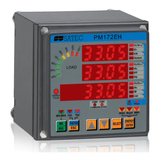
Chapter 1 Introduction 1. Chapter 1 Introduction 1.1 About this Manual This manual is intended for the user of the PM172EH Powermeter. This Powermeter is a microprocessor-based instrument used for the measurement, monitoring, and management of electrical parameters. This chapter gives an overview of this manual and an introduction to the PM172EH. - Page 8 Features Local Display: The front panel features bright LED displays (three windows, up to 134 pages, 6-digit energy counters) with adjustable update time, a bar graph showing percent load with respect to user- definable nominal load current, two communications receive/transmit LEDs, and an energy pulsing LED.
- Page 9 • 7 configurable TOU energy registers for accumulating kWh (import and export), kvarh (import and export), kVAh and energy from two external meters through 2 pulsing inputs • 3 configurable TOU Maximum Demand registers for recording maximum kW (import and export), and kVA demands •...
- Page 10 PM172EH Dimensions 99-06020 Figure 1-1 PM172EH Dimensions Chapter 1 Introduction...
- Page 11 Measured Parameters NOTE: Real-time values are measured over 1 cycle of fundamental frequency; Average values are of 8, 16 or 32 Real-time values. # = setup via panel, $ = setup via PC Parameter Display Comm. Analog Pulse Alarm Average Values Average RMS Voltage per phase Average RMS Current per phase Average Active Power per phase...
- Page 12 Parameter Display Comm. Analog Pulse Alarm Total Energy Total Active Energy Import & Export Total Reactive Energy Import & Export Total Reactive Energy Net Total Apparent Energy TOU Registers 7 Energy registers 3 Maximum demand registers (selectable kW import & export, kvar import & export, kVA demands) 16 Tariffs for each TOU register Harmonic Measurements...
- Page 13 Parameter Display Comm. Analog Pulse Alarm Min/Max THD, TDD, K-Factor per phase Voltage Disturbance Phase Rotation Day and Time Pulse Counters Remote Relay Control Inputs & Outputs Status Digital Inputs Status Alarm Relay Status Alarm Trigger/Setpoint Status Self-diagnostic Tests Chapter 1 Introduction...
-
Page 14: Chapter 2 Installation
Chapter 2 Installation 2. Chapter 2 Installation 2.1 Mechanical Installation HEX NUT #8-32 LOC K WASHER #8 3 . 3 FLAT WASHER #8 (WIDE) " 0 . 1 " 4 . 0 " STANDARD 4" ROUND I T C 99-05013 Figure 2-1 STEP 1 (4”... - Page 15 HEX NUT #8-32 . 0 m LOCK WASHER #8 FLAT WASHER #8 (WIDE) I T C DIN43700 92 x92mm 99-05014 Figure 2-2 STEP 1 (92x92mm Square DIN cut-out): Mount the Display Module on cut-out LONG STUD 99-05015 Figure 2-3 STEP 2: Assemble the 4 Locating Studs Chapter 2 Installation...
- Page 16 99-05016 Figure 2-4 STEP 3: Slide and Position the Powermeter on Locating Studs LOCK WASHER M4 THUMB NUT M4 99-05017 Figure 2-5 STEP 4: Affix the Powermeter Using the Thumb Nuts Chapter 2 Installation...
-
Page 17: Electrical Installation
2.2 Electrical Installation Before installation ensure that all incoming power sources are shut OFF. Failure to observe this practice can result in serious or even fatal injury and damage to equipment. Connections to the PM172EH are made via terminals located on the rear panel of the instrument as shown in Figure 2-6. - Page 18 2.2.2 Current Inputs To ensure accurate readings, the input current should not exceed 1.2A RMS and 1.76A amplitude for the 1A CT secondary, or 6A RMS and 8.8A amplitude for the 5A CT secondary. Copper wiring 2.5 – 3.5 mm (12 AWG) should be used.
- Page 19 Figure 2-7 Three Wire Direct Connection Using 2 CTs (2-element) Wiring Mode = 3dir2 LINE 1 (A) LINE 2 LOAD LINE 3 Shorting Switches Voltages Currents c99-05030 Figure 2-8 Four Wire WYE Direct Connection Using 3 CTs (3- element) Wiring Mode = 4LL3 or 4Ln3 Chapter 2 Installation...
- Page 20 Figure 2-9 Four Wire WYE Connection Using 3 PTs, 3 CTs (3- element) Wiring Mode = 4LL3 or 4Ln3 Figure 2-10 Three Wire Open Delta Connection Using 2 PTs, 2 CTs (2-element) Wiring Mode = 3OP2 Chapter 2 Installation...
- Page 21 Figure 2-11 Four Wire Wye Connection Using 2 PTs, 3 CTs (2½-element) Wiring Mode = 3LL3 or 3Ln3 This configuration will provide accurate power measurements only if the voltages are balanced. Figure 2-12 Three Wire Open Delta Connection Using 2 PTs, 3 CTs (2½-element) Wiring Mode = 3OP3 Chapter 2 Installation...
- Page 22 LINE 1(A) 240VAC L (B) LINE 2(B) 120VAC 240VAC LOAD 240VAC 208VAC LINE 3(C) 120VAC Shorting Switches Grounded delta connection Voltages Currents 120V 120V VOLTAGES DISPLAYED: 1. Line to neutral voltages: 120V; 208V; 120V. 2. Line to line voltages: 240V; 240V; 240V. c99-05031 Figure 2-13 Four Wire Delta Direct Connection Using 3 CTs...
- Page 23 2.2.7 Analog Output The PM172EH provides two optically isolated analog outputs with an internal power supply and current output options of 0-20 mA and 4-20 mA (current loop load of up to 500 Ohm), 0-1 mA and ±1 mA (current loop load of 10 kOhm).
-
Page 24: Chapter 3 Using The Menus
Chapter 3 Using the Menus 3. Chapter 3 Using the Menus Press and release to enter the setup mode. The primary menus SELECT will appear: Status Information Menu (see Chapter 6) Setup Options Menu Setup Change Menu (see Chapter 4) Press again to activate the window of the desired primary menu. - Page 25 SELECT ENTER Status Information Setup Options ENTER Setup Change Password PASS Reset Functions Phase Rotation PHAS Real Time Clock Relay Status Basic Setup Status Inputs bASc St.In Port Setup Counter #1 Port Cnt.1 Digital Inputs Counter #2 dinP Cnt.2 Counters Counter #3 Cnt.3 Analog Outputs...
-
Page 26: Chapter 4 Setup Menus
Chapter 4 Setup Menus 4. Chapter 4 Setup Menus Instrument setup can be performed directly on the front panel using the setup menus or via communications using PAS communication software, supplied with your instrument. For information on using PAS, refer to the user documentation provided. - Page 27 Table 4-1 Basic Setup Options (∗ default setting) Code Parameter Options Description ConF Wiring mode 3OP2 3-wire open delta using 2 CTs (2 element) 4Ln3∗ 4-wire Wye using 3 PTs (3 element), line to neutral voltage readings 3dir2 3-wire direct connection using 2 CTs (2 element) 4LL3 4-wire Wye using 3 PTs (3 element), line to...
-
Page 28: Communications Port Setup Menus
The waveform recorder #1 logs waveforms in series of records. A compound waveform can have as many as 1280 cycles recorded in 80 consequent records, each record comprising 16 waveform cycles. NOTES 1. The maximum value for CT PRIMARY CURRENT × PT RATIO is 10,000,000. If this product is greater, power related values will be zeroed. - Page 29 Table 4-2 Communications Options (∗ default setting) Code Parameter Options Description Prot Communications ASCII∗ ASCII protocol protocol Modbus RTU protocol dnP3 DNP3.0 protocol Interface standard RS-232 interface RS-422 interface 485∗ RS-485 interface Addr Address - 99 ASCII (1∗) Device address 1∗...
-
Page 30: Digital Inputs Setup Menu
4.3 Digital Inputs Setup Menu SELECT ENTER ENTER dinP This menu is used to set up the two digital inputs provided by the PM172EH. Each digital input can be allocated as: - a status input to monitor external contact status, or - a pulse input to sense pulses provided by an external source. -
Page 31: Pulse Counters Setup Menu
Digital inputs are numbered from the left to right. “0” indicates “not allocated”; “1” indicates “allocated”. Each digital input is set separately. NOTE Digital inputs configured as status inputs can be monitored via the Status Information Menu (see Chapter 6) and communications. The pulses being received via pulse inputs can be directed to one of the four pulse counters (see Section 4.4) and, at the same time, to any of the TOU energy registers. -
Page 32: Analog Output Setup Menu
4.5 Analog Output Setup Menu [This section is relevant to instruments ordered with this option] SELECT Aout ENTER ENTER This menu allows you to set up an output value and its zero and full scales for either of the two internal analog output channels. Table 4-3 explains the analog output setup options, and Table 4-4 lists all measurement parameters that can be directed to analog output. - Page 33 the entire range for power factor from -0 to +0, the scales would be specified as - 0.000/0.000. 3. For bi-directional analog output (±1 mA), the zero scale corresponds to the center of the scale range (0 mA) and the direction of current matches the sign of the output parameter.
- Page 34 Code Parameter Unit Scale Ar C2 Current L2 0 to Imax Ar C3 Current L3 0 to Imax Ar P Total kW kW/MW -Pmax to Pmax Ar q Total kvar kvar/Mvar -Pmax to Pmax Ar S Total kVA kVA/MVA 0 to Pmax Ar PF Total PF -0.000 to 0.000...
-
Page 35: Analog Expander Setup Menu
4.6 Analog Expander Setup Menu SELECT ENTER AEPn ENTER By connecting two optional AX-7 or AX-8 analog expanders (with outputs of 0-20 mA, 4-20 mA, 0-1 mA or ±1mA) to the PM172EH, an additional 14 (with AX-7) or 16 (with AX-8) external analog output channels can be provided. -
Page 36: Pulsing Output Setup Menu
4.7 Pulsing Output Setup Menu SELECT PulS ENTER ENTER This menu allows you to program either of the two relays provided by your instrument to output energy pulses. Available pulsing parameters are listed in Table 4-5. To select a pulse relay: rEL.1 Use the up/down arrow keys to scroll to the desired Ac.Ei... -
Page 37: Alarm/Event Setpoints Setup Menu
3. If a relay you allocated for pulsing has been engaged by an alarm/event setpoint, the setpoint is automatically disabled. 4.8 Alarm/Event Setpoints Setup Menu SELECT SEtP ENTER ENTER This menu is used to specify the events to be monitored by the setpoints, and actions to be triggered by those events. - Page 38 To select a setpoint: Scroll to the desired setpoint using the up/down arrow keys. To view the setup options for the setpoint: Press to activate the middle window. SELECT Use the up/down arrow keys to scroll to the desired setup option. The value associated with this option is displayed in the lower window.
- Page 39 Table 4-6 Setpoint Setup Options (middle window) Code Option Description LGC.1 - LGC.4 Logical operator Connects the trigger condition to previous (OR/AND) for the setpoint conditions using specified logical trigger operator trG.1 - trG.4 Trigger parameter The measurement parameter or signal to be monitored by the setpoint.
- Page 40 Code Parameter Unit Range Real-time Values per Phase rt Hi.C1 High current L1 0 to Imax rt Hi.C2 High current L2 0 to Imax rt Hi.C3 High current L3 0 to Imax rt Lo.C1 Low current L1 0 to Imax rt Lo.C2 Low current L2 0 to Imax...
- Page 41 Code Parameter Unit Range Hi d.C2 High ampere demand L2 0 to Imax Hi d.C3 High ampere demand L3 0 to Imax Hi d.P.i High block interval kW import demand kW/MW 0 to Pmax Hi d.P.E High block interval kW export demand kW/MW 0 to Pmax Hi d.q.i...
- Page 42 Code Parameter Unit Range Πon Month 1-12 Π.dAY Day of month 1-31 hour Hour 0-23 Πin Minutes 0-59 Seconds 0-59 Event Flags FG1.On Event flag #1 ON FG2.On Event flag #2 ON FG3.On Event flag #3 ON FG4.On Event flag #4 ON FG5.On Event flag #5 ON FG6.On...
- Page 43 voltage in other modes. See Section 4.1, Basic Setup Menu, for information on setting the nominal voltage in your meter. When the 4LN3 or 3LN3 wiring mode is selected, the voltages will be line-to- neutral; for any other wiring mode they will be line-to-line voltages. Table 4-8 Setpoint Actions (lower window, when middle window is Act) Code Action...
-
Page 44: Timers Setup Menu
Operate/release actions via relays are automatically recorded to the event log whenever an electrical quantity, status input or phase reversal trigger is used. Setpoint operation and release are recorded to the event log. 4.9 Timers Setup Menu SELECT ENTER ENTER This menu allows you to access the two interval timers provided by the PM172EH which can trigger setpoints on a user-defined time interval basis. -
Page 45: Rtc Setup Menu
4.10 RTC Setup Menu SELECT ENTER ENTER This menu allows you to view and set the time, date and day of week in the onboard Real Time Clock (RTC), and to modify the Daylight Savings Time (DST) settings for your time zone. The time is displayed as HH.MM.SS, where the hour and hour minute are shown in the middle window separated by a... - Page 46 To select an option sub-menu: From the upper window, use the up/down arrow keys to scroll to the desired sub-menu (time, date, weekday, or DST). To change time, date, day of week (not seconds) or DST setting: Press to activate the desired item. When in the time SELECT setup sub-menu, the hour and minutes indications are now frozen to allow you to adjust them.
-
Page 47: Display Setup Menu
4.11 Display Setup Menu SELECT diSP ENTER ENTER This menu allows you to view and change display properties. Table 4-9 lists available options with their code names and applicable ranges. Table 4-9 Display Options (∗ default setting) Display Code Parameter Options Description UPdt... -
Page 48: User Selectable Options Menu
To select a display option: Press to activate the middle window, and then use SELECT the up/down arrow keys to scroll to the desired option. To change the display option: Press to activate the lower window. SELECT Use the up/down arrow keys to set the desired option. Press to store your new setting or press ENTER... - Page 49 Table 4-10 User Selectable Options (∗ default settings) Code Parameter Option Description P.cAL Power calculation mode Using reactive power rEAc∗ nAct Using non-active power roLL Energy roll value 10.E4 10,000 kWh 10.E5 100,000 kWh 10.E6 1,000,000 kWh 10.E7 10,000,000 kWh 10.E8 100,000,000 kWh 10.E9∗...
- Page 50 Energy roll value example: If roll value = 10.E4, the energy counter contains 4 digits, i.e., energy is displayed up to 9.999 MWh (Mvarh, MVAh) with resolution 0.001 MWh. Rollover Maximum Energy Maximum Display Display Resolution Value kWh (kvarh, Reading MWh (Mvarh, kVAh) MWh (Mvarh, MVAh)
-
Page 51: Relay Operation Control Menu
4.13 Relay Operation Control Menu SELECT ENTER rELo ENTER This menu allows you to set the relay operation mode: non-failsafe or failsafe. Failsafe relay operation is the opposite of normal operation where relay contacts are closed when a relay is operated (activated), and are open when a relay is released (de-activated). -
Page 52: Access Control Menu
4.14 Access Control Menu SELECT AccS ENTER ENTER This menu can only be accessed via the Setup Change Menu (CHG). It is used in order to: • change the user password • enable or disable password check from the front panel keypad •... -
Page 53: Reset Menu
Store your password in a safe place. If you cannot provide the correct password, contact your local distributor for the super-user password to override password protection. 4.15 Reset Menu SELECT ENTER ENTER This menu allows you to reset to zero the accumulators and Min/Max registers in your instrument. - Page 54 NOTE If changing data in the instrument via the front panel is not secured by a password, the fast reset of the Min/Max registers, maximum demands and total energies can be made from the data display mode (see Section 5.1) and counters from the Status Information Menu (see Section 6.1) without entering the reset menu.
-
Page 55: Chapter 5 Data Display
Chapter 5 Data Display 5. Chapter 5 Data Display 5.1 Navigating in the Display Mode The front panel has a simple interface that allows you to display numerous measurement parameters in a total of 134 display pages. For easier reading, the parameters are divided into four groups, each accessible by a designated key. - Page 56 Table 5-1 lists all displayed parameters and their LED indicators. Load Bar Graph The load bar graph displays the amount, in percent, of the current load with respect to user-defined nominal load current. The highest current measured by the PM172EH is divided by the nominal load current as defined in the Display Setup Menu (see Section 4.11) and expressed as a percent by the LEDs (40% to 110%) which are lit.
- Page 57 Selecting Common Measurements (Main Screen) Press the key pointed to by the illuminated arrow LED below the front panel display. If no LED is lit up, this means that the front panel displays the common measurements parameters. Selecting Total Harmonic Measurements Press the key until the THD/HD% LED is H/ESC...
-
Page 58: Data Display Formats
• Min/Max log registers: select a Min/Max page from the Min/Max measurements display (where Lo or Hi is displayed at the left in the lower window). • Ampere and volt maximum demands: select the ampere or volt maximum demand page from the Min/Max measurements display (where Hd is displayed at the left in the lower window, and volts or amps arrow LEDs at the right are lit). - Page 59 Ph.L1 Label Power factor L1 kW L1 kW/MW kVA L1 kVA/MVA Ph.L1 Label kvar kvar L1 kvar/Mvar Ph.L2 Label Power factor L2 kW L2 kW/MW kVA L2 kVA/MVA Ph.L2 Label kvar kvar L2 kvar/Mvar Ph.L3 Label Power factor L3 kW L3 kW/MW kVA L3 kVA/MVA...
- Page 60 A NEUT Minimum neutral current Minimum frequency kvar Minimum total kvar kvar/Mvar Label V1/V1-2 Maximum voltage L1/L12 V/kV V2/V2-3 Maximum voltage L2/L23 V/kV V3/V3-1 Maximum voltage L3/L31 V/kV Maximum current L1 Maximum current L2 Maximum current L3 Maximum total kVA kVA/MVA Maximum total power factor Maximum total kW...
- Page 61 Total Harmonics THD/HD% V1/V1-2 Voltage THD L1/L12 Voltage THD L2/L23 V2/V2-3 V3/V3-1 thd Voltage THD L3 Current THD L1 Current THD L2 thd Current THD L3 Current TDD L1 Current TDD L2 tdd Current TDD L3 Current K-Factor L1 Current K-Factor L2 HF Current K-Factor L3 Individual Voltage Harmonics THD/HD%...
- Page 62 Total Energies Ac.En. Label Label MWh import Mvarh rE.En. Label Label Mvarh import Mvarh Label MVAh AP.En. MVAh MVAh Ac.En. Label Label MWh export Mvarh rE.En. Label Label Mvarh export Mvarh Chapter 5 Data Display...
- Page 63 Phase Energies Ac.En. Label IP.L1 Label MWh import L1 Mvarh rE.En. Label IP.L1 Label Mvarh import L1 Mvarh Label MVAh AP.En. Label MVAh L1 MVAh Ac.En. Label IP.L2 Label MWh import L2 Mvarh rE.En. Label IP.L2 Label Mvarh import L2 Mvarh MVAh AP.En.
-
Page 64: Self-Test Diagnostics Display
Per phase power and power factor readings are displayed only in 4LN3/4LL3 and 3LN3/3LL3 wiring modes (see Section 4.1) if the phase power display is enabled in the Display Setup menu (see Section 4.11). Phase energy readings are displayed only in 4LN3/4LL3 and 3LN3/3LL3 wiring modes (see Section 4.1) if they are enabled in the User Selectable Options menu (see Section 4.12). -
Page 65: Chapter 6 Viewing Status Information
Chapter 6 Viewing Status Information 6. Chapter 6 Viewing Status Information The Status Information Menu (STA) is used to view the status of various instrument features. 6.1 The Status Information Menu SELECT ENTER To enter the Status Information Menu: From the display mode, press to enter the SELECT Primary Selection Menu. -
Page 66: Status Display Formats
6.2 Status Display Formats Table 6-1 lists all the displays available from the Status Information Menu. The display windows are labeled in the table as follows: 1=upper window, 2=middle window, 3=lower window. Table 6-1 Status Information Page Window Parameter Digits Unit PHAS. - Page 67 Page Window Parameter Digits Unit DLG.7 Label Number of records in Data log #7 Data log #7 percent full DLG.8 Label Number of records in Data log #8 Data log #8 percent full FLG.1 Label Number of records in Waveform log #1 Waveform log #1 percent full FLG.2 Label...
-
Page 68: Chapter 7 Communications
Chapter 7 Communications 7. Chapter 7 Communications A full description of the communications protocols is found in the PM172EH ASCII, Modbus and DNP 3.0 Communications Manuals provided on electronic media COM1 COM2 Transmit Data Plus Receive Data Plus Transmit Data Minus Receive Data Minus Chassis Ground Figure 7-1 RS-232/RS-422/RS-485 and RS-422/RS-485 Terminal... - Page 69 Modem Connections COM1 – RS232 Figure 7-6 Connection for Figure 7-7 Connection for 25-pin Modem 9-pin Modem Connector Connector Computer Connections COM1 - RS-422/RS-485 RS-422 (MALE) TO SATEC CONVERTER TO PM172 COM1 RS-422 CABLE Figure 7-8 COM1 RS-422/RS-485 Connections Chapter 7 Communications...
- Page 70 Computer Connections COM2 - RS-422/RS-485 R1, R2 ≅ 200-500 Ohm, R1, R2 ≅ 200-500 Ohm, 0.5 W 0.5 W Figure 7-9 RS-422 Multidrop Figure 77-10 RS-422 Multidrop Connection, 25-Pin PC Port Connection, 9-Pin PC Port R1, R2 ≅ 200-500 Ohm, R1, R2 ≅...
-
Page 71: Appendix A Technical Specifications
Appendix A Technical Specifications 8. Appendix A Technical Specifications Input and Output Ratings 3 Galvanically Isolated Voltage inputs: 120V option Input using PT (up to 120V+20% line-to- line voltage) Burden: <0.15 VA 690V option Direct input (up to 690V +15% line-to-line voltage) Burden: <0.5 VA Input using PT... - Page 72 Power Supply (factory set) Galvanically isolated 120&230 V AC and 85-265VAC 50/60 Hz and 88-290VDC Burden 10 W 110&220 V DC Option 12 V DC 9.6 - 19 VDC Option 24 V DC 19 - 37 VDC Option 48 V DC 37 - 72 VDC Environmental Conditions Operating temperature...
- Page 73 Measurement Specifications Parameter Full scale Accuracy, % Range Display resolution (%Rdg) @ range Conditions Voltage 120V×PT @ 120V 10% to 120% FS 0 to 999,000 V Direct wiring (PT=1): 400V×PT @ 690V 0.1 V @ 0.1V to 999.9 V Wiring via PTs (PT>1): 0.001 kV @ 0.001kV to 9.999 kV ≤0.1% @ 10.00 kV to 999.0 kV Starting voltage 1.5% FS...
- Page 74 Parameter Full scale Accuracy, % Range Display resolution (%Rdg) @ range Conditions Apparent power 0.36×PT×CT @ 120V input 0.02 0 to Direct wiring (PT=1): 1.2×PT×CT @ 690V input 2,000,000 kVA 0.001 kVA @ 0.001kVA to 9.999 kVA Wiring via PTs (PT>1): 0.001 MVA @ 0.001MVA to 9.999 MVA ≤0.1% @ 10.00 MVA to 2000 MVA Power factor...
- Page 75 Parameter Full scale Accuracy, % Range Display resolution (%Rdg) @ range Conditions Harmonic active 0.36×PT×CT @ 120V input PF = 1 -2,000,000 to Direct wiring (PT=1): power 1.2×PT×CT @ 690V input |PF| ≥ 0.5 +2,000,000 kW 0.001 kW @ 0.001kW to 9.999 kW Wiring via PTs (PT>1): 0.001 MW @ 0.001MW to 9.999 MW ≤0.1% @ 10.00 MW to 2000 MW...
- Page 76 Parameter Full scale Accuracy, % Range Display resolution (%Rdg) @ range Conditions Apparent energy Under conditions of Class 0.5S 0 to 1 kVAh @ 1 to 999,999 kVAh (IEC 687-1992-6) 999,999 MVAh 10 kVAh @ 1000 to 9,999.99 MVAh 100 kVAh @ 10,000 to 99,999.9 MVAh 1MVAh @ 100,000 to 999,999 MVAh PT = external potential transformer ratio CT, CT Primary Current = primary current rating of external current transformer...
-
Page 77: Appendix B Using Setpoints
Appendix B Using Setpoints 9. Appendix B Using Setpoints The PM172EH has an embedded logical controller that can run different actions in response to user-defined internal and external events. Unlike a PLC, the PM172EH uses a simplified setpoint programming technique that allows the user to define a logical expression based on measured analog and digital values that will produce a required action. - Page 78 Using Binary Triggers Binary (digital) triggers, like digital inputs, relays, or internal static and pulsed events, are tested for ON (closed/set) or OFF (open/cleared) status. The binary events are divided into two types: static events and pulsed events. Static events are level-sensitive events. A static event is asserted all the time while the corresponding condition exists.
- Page 79 Using Time Triggers If you want the setpoint actions to be synchronized with the clock, for example, to provide synchronous recording interval data every 15 minutes or each hour, or to output time pulses through relay contacts, use the time triggers that generate static events synchronized to the device clock.
- Page 80 Up to four programmable actions can be performed in sequence on setpoint status transition when a setpoint event is asserted. Generally, setpoint actions are performed independently for each setpoint and can be repeated a number of times for the same target. The exceptions are relay operations, data logging and waveform logging that are shared for each separate target between all setpoints using an OR scheme.
-
Page 81: Appendix C Configuring Tou
Appendix C Configuring TOU 10. Appendix C Configuring TOU The PM172EH provides 7 TOU energy and 3 TOU maximum demand registers that can be linked to any internal energy source or to any external pulse source that delivers energy pulses through the device digital inputs. - Page 82 Select the start time for each tariff change point and the corresponding active tariff number. Repeat the setup for all types of days that have a different tariff schedule. The first tariff change point is fixed at 00:00 hours, and the last tariff change you specified will be in use until 00:00 hours on the next day.
-
Page 83: Appendix D Event And Data Logging
Appendix D Event and Data Logging 11. Appendix D Event and Data Logging The PM172EH has a 0.5-Megabyte onboard non-volatile memory for data, event and waveform recording. Before using event and data recorders, the PM172EH memory should be partitioned between log files. The device memory is fully configurable. The user defines how much memory to allocate for each log file. - Page 84 Option Range Description Record size Shows the size of the file record for a single channel or section. It is set automatically depending on the file and on the number of parameters in the data record Parameters Defines the number of parameters in a single data record for data log files.
- Page 85 The data recorder can record up to 16 data parameters per record in each of 8 data log files. The list of parameters is configured individually for each data log file. Before configuring data log parameters in your device, you should allocate memory for the data log and specify how many parameters each record will contain.
- Page 86 Setpoint #1 is preset at the factory to trigger Data Logs #1 and #2 in 15 min intervals. TOU Energy/Demand Profile Recording Data Log #7 and Data Log #8 can be configured to store a TOU monthly profile log and a TOU daily profile log respectively. A TOU profile log file is organized as a multi-section file that has a separate section for each TOU energy and maximum demand register.
-
Page 87: Appendix E Power Quality Setup
Appendix E Power Quality Setup 12. Appendix D Event and Data Logging The PM172EH can provide detection and registration of power quality events such as: • Voltage dips and interruptions • Voltage swells and overvoltages • Frequency variations • Voltage harmonic distortion The following table gives an example of programming setpoints for detection and recording power quality events. - Page 88 Fast transient voltages will trigger the Waveform Recorder to log voltage and current waveforms at the time of the event. Note that the recorded voltage waveforms will represent line-to-neutral voltages in all wiring modes except of Open Delta where they will be line-to-line voltages. The voltage disturbance threshold is defined in percent of the line-to-neutral or line-to-line nominal voltage respectively.
- Page 89 INDEX accuracy, 43, 73 54, 56, 57, 58, 60, 61, 70, 71, active energy, 72 72, 73 active power, 48, 70, 71, 72 power demand, 5, 26, 29, 40 ampere demand, 5, 26, 39, 40, 58 power factor, 71 analog output, 1, 7, 27, 31, 32, 34, power source , 1, 16 PT, 5, 17, 26, 27, 33, 60, 68, 70, analog outputs, 27...
- Page 90 NOTES Index...
Need help?
Do you have a question about the PM172EH Series and is the answer not in the manual?
Questions and answers