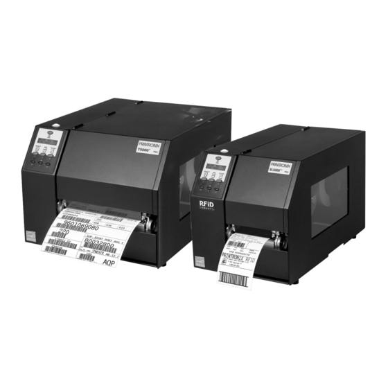
Printronix T5204R Administrator's Manual
Sl/t5r energy saver rfid smart label and thermal printers
Hide thumbs
Also See for T5204R:
- Quick reference manual (28 pages) ,
- Specifications (2 pages) ,
- User manual (396 pages)
Table of Contents
Advertisement
Quick Links
Advertisement
Table of Contents

Related Manuals for Printronix T5204R


Summary of Contents for Printronix T5204R
- Page 1 Administrator’s Manual SL/T5R Energy Saver RFID Smart Label and Thermal Printers...
- Page 3 Printronix makes no representations or warranties of any kind regarding this material, including, but not limited to, implied warranties of merchantability and fitness for a particular purpose. Printronix shall not be held responsible for errors contained herein or any omissions from this material or for any damages, whether direct, indirect, incidental or consequential, in connection with the furnishing, distribution, performance or use of this material.
-
Page 5: Table Of Contents
Table of Contents 1 Introduction ............11 The SL/T5R Energy Saver Family of Printers........11 Standard Features ................ 12 Optional Features................13 Thermal Printer Technology ..............14 The Printing Process ..............14 Dynamic Print Control ..............15 Warnings and Special Information............15 Manual Conventions ................ - Page 6 Table of Contents Running Auto Calibrate ..............60 Running Media Profile ..............62 Running Manual Calibrate............. 66 Cleaning....................68 Exterior Cleaning................68 Interior Cleaning ................68 Cleaning the Printhead, Platen Roller, Media Sensors and Media Damper................69 3 Configuring The Printer ........73 Overview....................
- Page 7 Table of Contents PGL SETUP..................168 VGL SETUP..................170 P-SERIES SETUP ................172 P-SER XQ SETUP................174 SERIAL MATRIX SETUP ..............176 PROPRINTER XL SETUP..............178 EPSON FX SETUP................180 Emulation Submenus ..............182 DIAGNOSTICS .................. 225 DIAGNOSTICS Submenus ............226 PARALLEL PORT................
- Page 8 Downloading Software through the NIC ..........269 Downloading Software through the NIC using FTP ......270 Downloading Software through the USB Port........272 Downloading Software through the Printronix Windows Driver ..273 Downloading Software if Flash Contains Only Boot or Corrupt Code ..................274 Using TrueType Fonts ...............
- Page 9 Acoustic Specifications ............... 339 Maximum Page Length ............... 340 B Printer Options ..........341 Hardware Options................341 Interface Options ................. 342 Supplies and Accessories..............343 Genuine Printronix Thermal Transfer Ribbons......344 Genuine Printronix Media............345 Accessories ................. 347 C ASCII Control Codes......... 349...
- Page 10 The PTX_SETUP Commands ............361 General Commands ..............362 Thermal Commands..............369 H Customer Support ..........371 Printronix Customer Support Center..........371 Printronix Supplies Department ..........371 Corporate Offices ................ 372 I Glossary ............373 J Communication Notices and Warranties... 379 Communication Notices..............
-
Page 11: Introduction
NOTE: All 4” models are Smart Ready. Table 1. The T5R, Smart Ready, and SmartLine Series Max Print Printing Max Print Version Speed (ips) Density (dpi) Width (inches) T5204R T5204R DT* SL5204R T5304R T5304R DT* SL5304R SL5304R T5206R SL5206R T5306R SL5306R... -
Page 12: Standard Features
. Provides printer system commands for text, barcodes, graphics, lines, and boxes. • Printronix VGL. Emulates the QMS Code V™ Version II programming language to produce on-line forms, bar codes, and alphanumeric text generation in both normal and high resolution. -
Page 13: Optional Features
Optional Features • Serial: RS-232 • USB 2.0 Universal Serial Bus NOTE: The interface cable needed to connect the printer to the host device is supplied by the user. • Tear-Off Mode: Positions the label at the tear-off position and detects its removal before printing the next label. -
Page 14: Thermal Printer Technology
Chapter Thermal Printer Technology • Online Barcode Validator: Analyzes each bar code to ensure it meets stringent scanning standards. This inspection validates the symbology specifications of both linear and PDF417 bar code images. Bad bar code labels are cancelled and good replacement labels are printed automatically. -
Page 15: Dynamic Print Control
Dynamic Print Control Dynamic Print Control Dynamic print control is a unique feature of your thermal printer that provides excellent print quality by preventing unevenness of print density. Print quality largely depends on how the thermal paper or the thermal ribbon and thermal transfer paper responds to the heat of the thermal printhead. -
Page 16: Thermal Consumables
Most of these media options can be die-cut for easy label applications. The wide selection of media sizes and face stocks have been tested with Printronix ribbons for print quality and usage. Consult your Genuine Printronix Supplies Catalog, call the Printronix Customer Support Center (see page 371), or access the Printronix web page at www.printronix.com. -
Page 17: Ribbons
Ribbons Ribbons Printronix offers a wide range of ribbons specifically engineered to enhance printing capabilities and to prevent premature printhead wear. Therefore, you should use a Genuine Printronix Thermal Ribbon in your printer. See “Genuine Printronix Thermal Transfer Ribbons” on page 344 for more information. - Page 18 Chapter Setting Up the Printer Foam 4. Remove the foam pad between the pivoting deck and the frame. Pivoting Deck Platen Deck Lock Foam Pad Lever Printhead 5. Open the pivoting deck by rotating the blue deck lock lever fully clockwise.
-
Page 19: Installation
Installation Installation The following sections will guide you through the printer installation process. 1. Place the printer on a flat level surface that allows easy access to all sides of the printer. CAUTION Never operate the printer while it is resting on its side or upside down. 2. - Page 20 Chapter Setting Up the Printer 5. Attach Interface: a. Parallel Interface Attach a suitable parallel printer cable from the computer to the Centronics/IEEE 1284 interface connector at the back of the printer. Snap the bail locks to the Centronics connector to secure the interface cable to the printer.
- Page 21 Installation If your printer is equipped with the optional Coax/Twinax, and/or optional RS-422, the rear I/O panel will appear as illustrated below. NOTE: Autoswitching does not support simultaneous switching between coax and twinax interfaces. However, autoswitching supports all interfaces including coax or twinax. Auto Switching is described on page 281.
- Page 22 Chapter Setting Up the Printer If your printer is equipped with the optional Wireless and Optional GPIO it will appear as illustrated below. Wireless And GPIO Interface Panel Wireless Antenna P A R A L L E L S T A T D E B U Wireless Interface...
-
Page 23: Operation
Operation Controls and Indicators Power Switch The power switch is located on the bottom back panel of the printer. To apply power, place the switch in the | (ON) position. When you first power on the printer, a series of initialization messages will appear on the Liquid Crystal Display (LCD) on the control panel. - Page 24 Chapter Controls and Indicators Status and Display Indicators...
- Page 25 Control Panel Control Panel Keys...
- Page 26 Chapter Controls and Indicators Control Panel Keys (cont.)
-
Page 27: Powering On The Printer
Powering On the Printer Powering On the Printer When you power on the printer, it executes a self-test. During the self-test, the LCD momentarily displays the DPI resolution (203 or 300 DPI) of the installed printhead. The default power-on state is online. Once the printer has successfully initialized, the ONLINE status indicator light illuminates, and the LCD indicates the communication interface selected and the emulation selected. -
Page 28: Loading Media And Ribbon
Chapter Loading Media and Ribbon • Peel-Off. When the optional internal rewinder is installed, the printer prints and peels die-cut labels from the liner without user assistance. The label liner is wound on the rewinder. The printer waits for you to take away the label before printing the next one (on-demand printing). -
Page 29: Loading Roll Media
Loading Roll Media Loading Roll Media Media Cover Media Hanger Media Hanger Guide Pivoting Deck Media Width Guide Media Damper Deck Lock Lever 1. Open the media cover. 2. Slide the blue media hanger guide outward to the end of the media hanger, and flip it up horizontally. - Page 30 Chapter Loading Media and Ribbon Media Roll Media Hanger Media Hanger Guide 5. Slide a roll of media onto and towards the back of the media hanger. The media feeds from the top of the roll and towards the front of the printer. 6.
- Page 31 Loading Roll Media Media and Ribbon Loading Instruction Media Printhead Media Damper Platen (Rubber Drive Roller) 7. Thread the media under the media damper and then between the platen (rubber drive roller) and the printhead. You can also refer to the arrows on the printer frame or to the label inside the media cover for media loading instructions.
- Page 32 Chapter Loading Media and Ribbon Lower Media Sensor Media Sensor Handle Media Guard Media Width Fixed Guide Guide Media Damper 8. Verify that the left (inside) edge of the media is against the fixed guide on the bottom of the media damper. 9.
- Page 33 Loading Roll Media Upper Sensor Visible Red Beam Lower Sensor Upper Sensor Handle Media Guard Opening 11. Slide the upper sensor directly over the lower sensor. Media (left edge) Guide Notch 12. Align the left (inside) edge of the media with the guide notch located on the front edge of the tear bar.
- Page 34 Chapter Loading Media and Ribbon Pivoting Deck Deck Lock Lever 13. Close the pivoting deck and rotate the deck lock lever fully counterclockwise. This locks the pivoting deck and printhead assembly into the printing position. IMPORTANT Ensure the pivoting deck is down and locked before attempting to advance media or print.
- Page 35 Loading Roll Media For direct thermal operation (no ribbon required): • If you have not run an Auto Calibrate, do so now. See “Running Auto Calibrate” on page 60. • If you have already run an Auto Calibrate, complete the following steps: a.
-
Page 36: Loading Fanfold Media
Chapter Loading Media and Ribbon Loading Fanfold Media Media Cover Fanfold Tension Fanfold Media Media Pivoting Hanger Deck Guide Media Hanger Bottom Panel Opening Deck Lock Lever 1. Open the media cover. 2. Slide the media hanger guide outward to the end of the media hanger and rotate it upward to a horizontal position to remove any roll media. - Page 37 Loading Fanfold Media Lower Media Sensor Media Sensor Handle Media Guard Media Width Fixed Guide Guide Media Damper 8. Slide the media width guide outward to the end of the media damper. 9. Thread the media under the media damper and then between the platen (rubber drive roller) and the printhead.
- Page 38 Chapter Loading Media and Ribbon Media (left edge) Guide Notch 12. Align the left (inside) edge of the media with the guide notch located on the front edge of the tear bar. Pivoting Deck Deck Lock Lever 13. Close the pivoting deck and rotate the deck lock lever fully counterclockwise.
- Page 39 Loading Fanfold Media 15. Verify the printhead pressure is properly set. See “Printhead Pressure Adjustment” on page 52. 16. Verify the pressure blocks are properly positioned. See “Printhead Pressure Block Adjustments” on page 53. 17. Verify the Gap/Mark Sensor selection matches the type of media installed.
-
Page 40: Loading Ribbon
Chapter Loading Media and Ribbon Loading Ribbon Skip this section for 4 inch DT models or when using direct thermal printing. Ribbon Take-Up Core Ribbon Take-up Spindle Pivoting Deck Ribbon Supply Spindle Ribbon Roll Deck Lock Lever 1. Install the ribbon take-up core on the ribbon take-up spindle. NOTE: The first ribbon take-up core comes with the printer. - Page 41 Loading Ribbon Ribbon Printhead Media Rear Ribbon Guide Roller 183395 REV 4. Thread the end of the ribbon under the rear ribbon guide roller, then between the platen and the printhead. You can also refer to the arrows on the printer frame or to the upper-right corner of the label inside the media cover for ribbon loading instructions.
- Page 42 Chapter Loading Media and Ribbon Media Cover Media and Ribbon Loading Instructions Ribbon Take-up Core Ribbon Take-up Spindle IMPORTANT Do not attach the ribbon to the ribbon take-up spindle without a fiberboard take-up core installed. 5. Attach the ribbon to the ribbon take-up core on the ribbon take-up spindle using the adhesive on the ribbon leader.
-
Page 43: Using The Optional Internal Rewinder
Batch Rewind Mode Using the Optional Internal Rewinder The printer can be set up to rewind labels after they have been printed (Batch Rewind Mode) or to automatically peel labels from their backing and dispense them one at a time while rewinding the liner (Peel-Off Mode). Both modes require an internal rewinder, which is available as a factory installed or a field unit option. - Page 44 Chapter Using the Optional Internal Rewinder 2. The bottom of the plastic paper path is shaped like a hook and the top has a groove: a. Hook the bottom of the paper path under the bottom edge of the front door.
- Page 45 Batch Rewind Mode Media Paper Path Slot Rewinder Release Lever 2. Thread the media over the front of the paper path and through the opening under the front door toward the internal rewinder. IMPORTANT If you do not complete the following step, it will be extremely difficult to remove the printed labels from the rewinder.
- Page 46 Chapter Using the Optional Internal Rewinder Media Cover Deck Lock Lever 6. Press down on both sides of the pivoting deck and rotate the deck lock lever counterclockwise against its stop to place the printhead assembly into the printing position. 7.
- Page 47 Batch Rewind Mode Removing Printed Media from the Rewinder Release Lever Rewinder Printhead 1. Open the media cover. 2. Press the FEED key to advance the last printed label past the printhead, and tear the liner from behind the last printed label. 3.
-
Page 48: Label Peel-Off
Chapter Using the Optional Internal Rewinder Label Peel-Off You can set up the printer to automatically peel die-cut labels off their liner (backing) and dispense them one at a time while rewinding the liner. You can install the paper path to prevent long labels from accidentally adhering to the front door assembly, but it is normally not needed when using labels less than two inches long (see “Installing the Paper Path”... - Page 49 Label Peel-Off Back Flange Raised Ridge Rewinder Release Lever Slot Liner IMPORTANT If you do not complete the following step, it will be difficult to remove the liner from the rewinder. 6. Turn the release lever on the rewinder counterclockwise and lock it in place.
- Page 50 Chapter Using the Optional Internal Rewinder Media Cover Deck Lock Lever 12. Press down on both sides of the pivoting deck and rotate the deck lock lever fully counterclockwise. 13. Press the FEED key. The label advances to the peel-off position, and “Remove Label”...
-
Page 51: Removing The Paper Path
Removing the Paper Path Removing Label Liner from the Rewinder 1. Open the media cover. 2. Open the front door. 3. Tear the liner at the tear bar. 4. Manually rewind the remaining liner onto the rewinder by turning the rewinder counterclockwise. -
Page 52: Printing Adjustments
Chapter Printing Adjustments Printing Adjustments Printhead Pressure Adjustment Active Pressure Setting Printhead Pressure Adjustment Dial Sometimes you will need to adjust printhead pressure because of variations in media thickness and width. The printhead pressure adjustment dial is shown above. The value shown at the bottom of the dial is the active setting. In general, adjust printhead pressure to the lowest value which produces the desired print quality. -
Page 53: Printhead Pressure Block Adjustments
Printhead Pressure Block Adjustments Printhead Pressure Block Adjustments Right Pressure Block Right Pressure Block Pointer Left Pressure Block Lead Screw Pressure Block Knob Adjustment Scale Left Pressure Block Handle Printhead pressure block adjustments are used to obtain a uniform print density across the width of the installed media under a variety of media and ribbon conditions. -
Page 54: Positioning The Media Sensors
Chapter Printing Adjustments 3. Press the ↵ key to start the Grey test pattern. The pattern will start and continue to print. 4. Press ↵ again to stop printing. 5. Check the test pattern. If necessary reposition the pressure blocks to obtain a uniform print density across the media width. - Page 55 Positioning the Media Sensors Sensing Media with Horizontal Black Marks (Mark) or Media with No Label Length Indicators (Disable) Black Mark (underside Visible Red Beam of media) from Lower Sensor Lower Sensor Sensor Handle Media Guard Opening Sensing Media with Horizontal Black Marks Position the lower media sensor for detecting horizontal black marks located on the underside of media, and position the upper sensor above the lower sensor to provide a consistent background.
- Page 56 Chapter Printing Adjustments Sensing Media with Gaps, Notches, or Holes (Gap) Upper Sensor Visible Red Beam from Lower Sensor Media Guard Opening Position the lower media sensor for detecting gaps, notches, or holes in media with a white background. If using direct thermal media, position the upper sensor away from the lower sensor.
- Page 57 Positioning the Media Sensors Sensing Media with Dark Background Labels with Gaps (Advanced Gap) Upper Sensor Visible Red Beam Lower Sensor Upper Sensor Handle Media Guard Opening NOTE: Ribbon is not displayed in this illustration. The upper and lower sensors are designed to function with or without ribbon installed. The upper sensor and lower sensor are used together to detect liner gaps between die cut labels that have a black or dark background on white or clear liner.
- Page 58 Chapter Printing Adjustments Sensing Dark Background Media with Notches or Holes (Advanced Notch) Upper Sensor Handle Upper Sensor Visible Red Beam Lower Sensor Black line on underside of media Media Guard Opening NOTE: Ribbon is not displayed in this illustration. The upper and lower sensors are designed to function with or without ribbon installed.
-
Page 59: Sensing Different Media Types
Sensing Different Media Types Sensing Different Media Types The printer’s media sensors can detect the different types of label length indicators on a large variety of media types. This is accomplished by selecting the correct sensor option: Gap, Mark, Advanced Gap, Advanced Notch, or Disable under Gap/Mark Sensor in the CALIBRATE CTRL menu. -
Page 60: Running Auto Calibrate
Chapter Printing Adjustments Calibrating the Media Sensors Due to manufacturing differences in media and ribbon, the media sensors may have difficulty differentiating between the label and the liner or the label and the black mark. When this occurs, the printer may intermittently skip a label or display a fault message such as “GAP NOT DETECTED/See Manual”... - Page 61 Running Auto Calibrate 1. Press the PAUSE key until “OFFLINE” appears on the LCD. 2. Press ↓ and ↵ together until “ENTER SWITCH UNLOCKED” displays. 3. Press the TEST PRINT key until “Printer Tests/Auto Calibrate” displays. ↵ 4. Press . Media advances until it can accurately detect the label length indicators and then stops at the Top-of-Form position.
-
Page 62: Running Media Profile
Chapter Printing Adjustments Running Media Profile The Media Profile printout shows the relationship of the Paper Out Threshold and the Gap/Mark Threshold values, illustrates if and when each label length indicator is detected, and shows the difference between the label length indicators and the label. - Page 63 Running Media Profile 1023 0767 Paper Out (578) 0511 Gap Mark (421) 0255 0000 Figure 1. Media Profile Printout Gap Sensing This figure shows a Media Profile printout of a smart label where Gap/Mark Sensor is set to Gap in the CALIBRATE CTRL menu. In this example, the gap threshold value the printer selected (represented by the Gap/Mark dotted line) is too close to the amplitude of the antenna pulse.
- Page 64 Chapter Printing Adjustments To avoid this problem, increase the Threshold Range value to 60% or 70% in the CALIBRATE CTRL menu (the default is 50%), then run an Auto Calibrate again (Cross-Ref to Auto Calibrate). NOTE: Any changes to Threshold Range will not take effect until you run an Auto Calibrate again.
- Page 65 Running Media Profile Advanced Gap Sensing This figure shows a Media Profile printout of a smart label where Gap/Mark Sensor is set to Advanced Gap in the CALIBRATE CTRL menu. In this example, the gap threshold value the printer selected (represented by the Gap/Mark dotted line) is too close to the baseline (die cut label).
-
Page 66: Running Manual Calibrate
Chapter Printing Adjustments Media Sensor Position FEED 1023 0767 0511 Paper Out(301) 0255 Gap(160) 0000 Detected Amplitude Detected Amplitude Indicates Type of Gap/Mark of the Antenna of the Gap Sensing Selected Running Manual Calibrate Manual Calibrate should be performed only when the values derived from Auto Calibrate fail to improve the media sensors’... - Page 67 Running Manual Calibrate ↵ 5. Press to select Enable. An asterisk (*) appears next to “Enable.” 6. Press until “CALIBRATE CTRL” displays. ↵ 7. Press ↓ until “Manual Calibrate/Run Calibrate” displays, then press the 8. Follow the instructions displayed on the LCD. Example: “REMOVE RBN&MEDIA/Press Enter”...
-
Page 68: Cleaning
Chapter Cleaning Cleaning Depending on the media used, the printer may accumulate residues (media dust, adhesives, etc.) as a by-product of normal printing. To maintain top printing quality, you should remove these residues by cleaning the printer periodically. WARNING Set the printer power switch to O (Off) prior to performing any cleaning tasks. -
Page 69: Cleaning The Printhead, Platen Roller, Media Sensors And Media Damper
• Cleaning Agent - Clean the printhead using a Printhead Cleaning Pen, Printronix PN 203502-002 or an Isopropyl Alcohol Wipe, Printronix PN 254945-901. • Schedule - Clean the printhead each time you install a new roll of ribbon (thermal transfer print mode) or when you install a new roll or box of media (direct thermal print mode). - Page 70 Chapter Cleaning Platen Roller Cleaning Label parts, media dust, and adhesive residue on the platen can degrade print quality and cause voids in your label image. • Cleaning Agent - Use an isopropyl alcohol wipe or small amount of isopropyl alcohol on a clean cloth to clean the platen roller. •...
- Page 71 Cleaning the Printhead, Platen Roller, Media Sensors and Media Damper Pivoting Deck Printhead Heating Elements Peel/Tear Door Lower Media Sensor (visible with red LED) Printhead Cover/ Upper Media Sensor Deck Lock Platen Roller Lever Print Element Upper Sensor...
- Page 72 Chapter Cleaning Media Damper Cleaning The media damper and its media width guides (see page 32) can accumulate parts of labels, adhesive and paper dust residue that can prevent the proper guiding of labels. • Cleaning Agent - Use an isopropyl alcohol wipe or isopropyl alcohol on a clean cloth.
-
Page 73: Configuring The Printer
Configuring The Printer Overview This chapter provides information about: • Setting, saving, modifying, and printing configurations • Configuration menus • Downloading emulation and operating system software Setting Printer Configuration Parameters Configuration parameters are set from the control panel or are retrieved from the printer’s memory. -
Page 74: Selecting A Menu Option
Chapter Overview NOTE: In menus with numeric ranges of more than 50 numbers, hold down the + or − key for more than 2 seconds to move through the range in increments of 5. To move in increments of 1 again, release your hold on the + or −... -
Page 75: Changing Printer Settings
Changing Printer Settings IMPORTANT This change takes effect for all subsequent data and operations for the printer as soon as the ↵ key is pressed and the asterisk (*) is displayed. The configuration change(s) stay in effect only while the printer is powered on. -
Page 76: Saving A Configuration
Chapter Overview • SMT: Status (if RFID is installed. Refer to the RFID Labeling Reference manual.) • PAA: Status (if RFID is not installed) or − key to scroll 3. When the desired submenu displays, press the through the values or options. 4. -
Page 77: Auto Save Configuration
Auto Save Configuration 4. When the desired number displays, press the ↵ key to select it. The following message displays briefly: Saving Configuration When processing is completed, the display shows: Save Config. NOTE: If the configuration number has been previously saved and Protect Configs. -
Page 78: Specifying A Power-Up Configuration
Chapter Overview Specifying a Power-Up Configuration You can specify any one of the nine configurations (1-8 or Factory) as the power-up configuration: key until the following message displays: 1. Press the MENU MODE CONFIG. CONTROL 2. Press the ↓ key until the following message displays: Power-Up Config. -
Page 79: Modifying A Saved Configuration
Modifying a Saved Configuration Modifying a Saved Configuration You can change a saved configuration by rewriting over it. For example, you can modify Config. 1, shown below. Suppose you want to keep all the settings but you want to select the parallel Centronics interface instead of the IEEE 1284 interface. - Page 80 Chapter Overview 4. Before saving the modified configuration, you must delete the original configuration if the Protect Configs. option is enabled. a. Press the ↑ or ↓ key until the following message displays: Delete Config. or − key to cycle through the options (1-8). When the b.
-
Page 81: Printing A Configuration
Printing a Configuration Printing a Configuration We recommend that you print and store your configurations for future reference. The printout provides a list of the parameters that were set when you configured the printer. To print a configuration: 1. Press the key until the following message displays: MENU MODE CONFIG. -
Page 82: Menu Overview
Chapter Menu Overview Menu Overview QUICK RFID VALIDATOR CONFIG. MEDIA SETUP CONTROL CONTROL CONTROL Set the basic RFID encoder Online data Name, store, and Control various menus needed to setup and status validator setup retrieve up to parameters configure the reporting. - Page 83 ETHERNET OPTIONAL OPTIONAL PRINTER PARAMETER PORTS FEATURES MGMT Select optional Select optional Select PNE port host interfaces. features, such as type and port DATE for Real number. Time Clock. Press to select the next main menu. Press ↓ or ↑ to move within each main menu.
-
Page 84: Main Menu
Chapter Main Menu Main Menu QUICK RFID VALIDATOR CONFIG. SETUP CONTROL CONTROL (page 95) (page 104) Print Intensity Refer to the RFID Save Config. Refer to the Online Print Speed Load Config. Labeling Reference Data Validator Print Mode Print Config. Manual. - Page 85 MEDIA CALIBRATE PRINTER CONTROL CTRL CONTROL (page 107) (page 127) (page 135) Print Intensity Gap/Mark Sensor SMT: Status Print File List Print Speed Auto Calibrate PAA: Select Tool Auto Locking Print Mode Media Profile LP+ Emulation Set Lock Key Media Handling Sensed Distance CTHI Emulation Ptx Setup Parse...
- Page 86 Chapter Main Menu TWINAX SPC COAX SPC TWINAX COAX 2, 3, 7 2, 3, 4 2, 3, 4 2, 3, 7 SETUP SETUP SETUP SETUP (page 156) (page 158) (page 159) (page 153) Primary Sets Primary Sets SPC Type SPC Type Translation Tbl Translation Tbl Logical Buf Size...
- Page 87 IPDS SETUP 3270 SETUP 5250 SETUP SETUP (page 160) (page 164) (page 166) (page 168) Default Font Primary Sets Primary Sets Character Group Standard Sets Default Code Pag Translation Tbl Translation Tbl Select LPI Code Page Subset Active Char Set Active Char Set Define CR Code Emulation...
- Page 88 Chapter Main Menu SETUP SETUP SETUP SETUP (page 170) Refer to the ZGL ™ Refer to the TGL ™ Refer to the IGL ™ Select SFCC Power-up ^X Programmer’s Programmer’s Programmer’s Power-up ^F Reference Manual. Reference Manual. Reference Manual. Power-up ^PY Btm Margin Ctl Text Length Autoeject...
- Page 89 STGL IEGL SETUP SETUP SETUP SETUP Refer to the STGL ™ Refer to theDGL ™ Refer to the MGL ® Refer to the IEGL ® Programmer’s Programmer’s Programmer’s Programmer’s Reference Manual. Reference Manual. Reference Manual. Reference Manual. NOTES: Italicized items are available only when Admin User is set to Enable (in the PRINTER CONTROL menu).
- Page 90 Chapter Main Menu SER MATRIX PROPRINTER P-SERIES P-SERIES XQ 1, 2 1, 2 1, 6 1, 6 SETUP SETUP SETUP SETUP (page 176) (page 178) (page 172) (page 174) Select CPI Select CPI Select CPI Select CPI Select LPI Select LPI Select LPI Select LPI Typeface...
- Page 91 SERIAL EPSON FX DIAGNOSTICS PARALLEL 3, 4, 5 PORT SETUP PORT (page 233) (page 180) (page 225) (page 229) Select CPI Printer Tests Port Type Port Type Select LPI Test Count Data Bit 8 Baud Rate Typeface Software Build PI Ignored Word Length Character Group Feature File...
- Page 92 Chapter Main Menu C/T PORT USB PORT ETHERNET ETHERNET PORT ADDRESS (page 241) (page 242) (page 243) (page 244) IP Address SEG1: Port Type Buffer Size in K Timeout IP Address SEG2: Device Address Timeout Switch Out On IP Address SEG3: Timeout IP Address SEG4: Report Status...
- Page 93 WLAN ETHERNET WLAN PARAMS PARAMS ADDRESS (page 251) (page 246) (page 249) NetBIOS Protocol IP Address SEG1: Signal Strength WEP Key 2 BYTE1: ASCII Data Port IP Address SEG2: Operation Mode WEP Key 2 BYTE2: IPDS Data Port IP Address SEG3: SSID Name(01-15) WEP Key 2 BYTE3: Keep Alive Timer...
- Page 94 Chapter Main Menu KERBEROS WLAN PRINTER DATE PARAMS MGMT (page 263) (page 257) (page 260) (page 262) EAP Mode PNE Port Time/Date Kerberos Enable EAP User (01-15) Mgmt Protocol Kerb. Pwd(01-15) EAP User (16-30) PNE Port Number Kerb. Pwd(16-30) EAP User (32-32) PNE Port Timeout Kerb.
-
Page 95: Quick Setup
QUICK SETUP QUICK SETUP (from page 84) Print Print Print Media Paper Feed Label Intensity Speed Mode Handling Shift Length 2, 4 6 ips* Transfer* Tear-Off Strip* 0.00 inches* 4 or 6 inches* -15 to 15 1 ips to 10 ips Direct Tear-Off -1.00 to X inches... -
Page 96: Quick Setup Submenus
Chapter QUICK SETUP QUICK SETUP con’d (from page 95) SMT: Status PAA: Select Tool Disable* None* Enable CST-1 CST-2 Notes: * = Factory Default Appears only if RFID is installed and there is no CST bundle in the Flash File System. Appears only if RFID is not installed and there is a CST bundle in the Flash File System. - Page 97 QUICK SETUP Submenus Print Mode This option specifies the type of printing to be done. • Transfer (factory default). Indicates Thermal Transfer printing (ribbon installed). • Direct. Indicates Direct Thermal printing (no ribbon) and requires special heat sensitive media. Media Handling This option specifies how the printer will handle the media (labels or tag stock).
- Page 98 Chapter QUICK SETUP Label Length This option specifies the user-selected Label Length in inches or millimeters. In most applications, the user-selected Label Length will match the physical label length. Physical label length is the actual label length of the media installed.
- Page 99 QUICK SETUP Submenus The allowable Label Length range is 00.1 to 99.0 inches (2.5 - 2514.6mm) The factory defaults are listed below: Table 2. Factory Default Label Length Inches Lines Printer 152.4 T5X04 101.6 T5X06 152.4 T5X08 Maximum Label Length range is dependent on the Label Width value selected and printhead installed (203 or 300 DPI).
- Page 100 Chapter QUICK SETUP Orientation This menu item selects the image orientation to be used when printing the label. • Portrait (factory default). Portrait refers to vertical page orientation, where the height of a page is greater than its width. The top edge of the image is parallel to the leading edge of the media.
- Page 101 QUICK SETUP Submenus Trailing Edge 4 inches The top edge of FEED the image is parallel to the trailing edge of the 6 inches media. Leading Edge • Inv. Landscape. Inverse Landscape refers to horizontal orientation, where the width of a page is greater than its height. The top edge of the image is the right edge of the media (the left edge of the image is the trailing edge of the media).
- Page 102 Chapter QUICK SETUP • Gap. An alternative to Advanced Gap. The Top-of-Form position is the leading edge of the die cut label (trailing edge of the gap, notch, or hole). • Advanced Gap (factory default). Select when using media with a liner space between die-cut labels or when using tag stock with notches or holes as label length indicators on white background media or when using media that has liner gaps between die cut labels with black background.
- Page 103 QUICK SETUP Submenus Validator Funct. This menu appears only if a validator is installed. • Enable. The printer will command the validator to begin scanning and errors will be reported. The counters will be incremented while the validator is enabled. •...
-
Page 104: Config. Control
Chapter CONFIG. CONTROL CONFIG. CONTROL CONFIG. CONTROL (from page 84) Save Load Print Delete Power-Up Protect Config. Config. Config Config. Config. Configs. Factory* Current* All* Factory* Disable* 1 to 8 1 to 8 Factory 1 to 8 1 to 8 Enable Power-Up 1 to 8... -
Page 105: Config. Control Submenus
CONFIG. CONTROL Submenus CONFIG. CONTROL Submenus Save Config. This option allows you to save up to eight unique configurations to meet different print job requirements. This eliminates the need to change the parameter settings for each new job. The configurations are stored in memory and will not be lost if you turn off the printer. - Page 106 Chapter CONFIG. CONTROL Name Config (1-8) You may specify a 15-character name which can be used to refer to a configuration. The name you enter for a configuration will be used in the Load Config., Save Config., Print Config., Delete Config., and Power-Up Config. menus.
-
Page 107: Media Control
CONFIG. CONTROL Submenus MEDIA CONTROL MEDIA CONTROL (from page 85) Print Print Print Media Paper Feed Label Intensity Speed Mode Handling Shift Length 2, 4 6 ips* Transfer* Tear-Off Strip* 0.00 inches* 4 or 6 inches* -15 to 15 1 to 10 ips Direct Tear-Off -1.00 to X inches... -
Page 108: Media Control Submenus
Chapter MEDIA CONTROL MEDIA CONTROL (from page 107) Peel-Off Continuous TOF Detect Ticket Save TOF Adjust Mode Mode Fault Mode Mode Fast* Standard* 3 Labels* Disable* Disable* Standard Tear-Off 9 Labels Enable Enable Tear-Strip Full 1 Label Cut Strip TOF Adjust Ribbon Reverse Vertical DPI... -
Page 109: Print Speed
MEDIA CONTROL Submenus Print Speed This option specifies the speed in inches per second (ips) at which the media passes through the printer while printing. The range is from 1 to 10 ips (in increments of 1 ips). The factory default is 6 ips. NOTE: The maximum print speed varies based on maximum printer width and dot per inch (dpi) resolution of the printhead installed (203 or 300 dpi). - Page 110 Chapter MEDIA CONTROL Paper Feed Shift This option represents the distance to advance (+ shift) or pull back (– shift) the stop position of a label when Tear-Off Strip, Tear-Off, Peel-Off, or Cut media handling option is enabled. The allowable range is -1.00 inches to the current Label Length value setting, up to a maximum of 12.80 inches, in .01 inch increments.
- Page 111 MEDIA CONTROL Submenus When the Logical Label Length is greater than the Physical Label Length and Clip Page = Disable, the printer will continue to print the image onto the next physical label and ignore the gap or mark based on the label length value set in the MEDIA CONTROL menu.
- Page 112 Chapter MEDIA CONTROL Hor Image Shift This option specifies the amount to shift an image horizontally left (-) or right (+) for precise positioning on the label. The actual width of the image is not affected by this parameter. The allowable range is -1.00 through +1.00 inches in .01 inch increments.
- Page 113 MEDIA CONTROL Submenus • Landscape. Landscape refers to horizontal orientation, where the width of a page is greater than its height. The top edge of the image is the left edge of the media. The following illustration is an example, with the operator viewing the front of the printer.
- Page 114 The IGP/Auto Label Mapping feature allows backward compatibility of programs written for P5000 line-matrix printers using the Printronix PGL graphics language. It allows the printer to print two-up (or other multi-up) labels. Instead of printing multiple labels across the printer, it prints the leftmost label and the rightmost label, so the printout will be twice as long but half as wide.
- Page 115 MEDIA CONTROL Submenus Examples All of the examples below assume that the logical form length is set to the label length. Example 1: Simple Case Problem: A file has been constructed with two horizontally adjacent 4” labels for a printer with a physical width of 8”. The user now wants to use this file with a printer that has a 4”...
- Page 116 Chapter MEDIA CONTROL Example 2: Uneven Number Case Problem: A file has been constructed with three horizontally adjacent 2” labels. The user now desires to use this file with a printer that has a 4” physical width. Solution #1: The user sets Auto Label Width to 4” (the width of two labels), configures the Num Auto Labels to 2, and enables the Auto Label Mapping feature.
- Page 117 MEDIA CONTROL Submenus Example 3: Past Maximum File Width Problem: A file has been constructed with three horizontally adjacent 4” labels. The user now desires to use this file with a printer that has a 8” physical width. The user should have used a solution similar to one of the solutions in the section above, but the user erroneously enters an Auto Label Width of 12”...
- Page 118 Chapter MEDIA CONTROL Num Auto Labels The desired number of labels to be printed vertically adjacent on the form. The value is selectable with a range of 2 through 40 (T5X04), 2 through 21 (T5X06) and 2 through 17 (T5X08). The factory default is 2.
- Page 119 MEDIA CONTROL Submenus Print Direction and Orientation are two independent options that can be combined to produce the following results depending on the Active IGP Emulation: Table 4. Head First Print Direction Result in Active Emulations Orientation Option Option (PGL or VGL) Head First Portrait Portrait...
- Page 120 Chapter MEDIA CONTROL Pre-Peel Mode • Disable (factory default). • Enable. When Media Handling = Peel-Off and Peel-Off Mode = Standard, enabling Pre-Peel Mode adds a forward and reverse motion to each label prior to printing. The added forward pre-peel motion temporarily breaks the die cut label from the liner, and the reverse motion places the label back on the liner prior to printing, peeling, or dispensing the label.
- Page 121 MEDIA CONTROL Submenus Clip Page This option determines how the printer handles images that are too large for one physical page length when using gap or black mark media. • Enable (factory default). When the user-selected page length is greater than the physical page length, the printer clips the excess data to fit the physical page.
- Page 122 Chapter MEDIA CONTROL Error Recover This option determines how the printer handles data that was printing when an error occurred. • Disable (factory default). The printer will not reprint the label that was printing when the error condition occurred. • Enable.
- Page 123 MEDIA CONTROL Submenus Units This item selects either millimeters or inches as the unit of measure. The options are In Inches (factory default) and In Millimeters. Set Label Length This feature selects whether the Sensed Distance value derived from an Auto or Manual Calibrate will be used to set the Label Length value in the MEDIA CONTROL menu (and the QUICK SETUP menu).
-
Page 124: Continuous Mode
Chapter MEDIA CONTROL “End of Image” printing is affected by the “Clip Page” option (under MEDIA Control). See “Clip Page” on page 121 for more details. Peel-Off Mode When Peel-Off Media Handling mode (see page 109) is enabled, this feature allows selection of two different media motions for automatic label peel-off. - Page 125 MEDIA CONTROL Submenus TOF Detect Fault Allows selection of three different TOF (Top-of-Form) detection faults. NOTE: The correct Label Length value, equal to the physical length of the installed label, must be entered in the QUICK SETUP or MEDIA CONTROL menu. •...
- Page 126 Chapter MEDIA CONTROL TOF Adjust Mode • Enable. This option enables the “TOF Adjust” distance set using the TOF Adjust menu (see TOF Adjust below). • Disable (factory default). his option disables the “TOF Adjust” distance set using the TOF Adjust menu (see TOF Adjust below). TOF Adjust This opton sets the distance from the Top Of Form (TOF) that is left blank (unprinted) after a label has been removed in Tear-Off strip or Tear-Off mode.
-
Page 127: Calibrate Ctrl
MEDIA CONTROL Submenus CALIBRATE CTRL CALIBRATE CTRL (from page 85) Gap/Mark Auto Media Sensed Gap/Mark Paper Out Sensor Calibrate Profile Distance Thresh Thresh Disable Run Calibrate Print Profile 0.00 inches 0000 to 1023 0000 to 1023 Mark Advanced Gap* Advanced Notch HeadClose Paper Out Manual... -
Page 128: Calibrate Ctrl Submenus
Chapter CALIBRATE CTRL CALIBRATE CTRL Submenus Gap/Mark Sensor The available options specify the sensor type needed for detecting the Top-of- Form position on media with label length indicators (gaps, notches, holes, or black marks). • Disable. Select when using media with no label length indicators (no gaps, notches, holes, or black marks), or when you want the printer to ignore all existing label length indicators on the installed media. - Page 129 CALIBRATE CTRL Submenus Auto Calibrate is completed successfully when the Sensed Distance displayed correctly matches that of the installed media. When Gap is selected, the Sensed Distance should match the length from the trailing edge of one gap to the trailing edge of the next gap (one label + one gap). When Mark is selected, the Sensed Distance should match the length from the leading edge of one black mark to the leading edge of the next black mark.
- Page 130 Chapter CALIBRATE CTRL Paper Out Thresh This menu item selects a value that, when exceeded by the output of the media sensor, is recognized by the printer as a paper out condition. When Auto or Manual Calibrate is performed, the value displayed is equal to the paper out threshold value set by this procedure.
- Page 131 CALIBRATE CTRL Submenus Pwr Up Action • Disable. No movement at power up. • Auto-Cal (factory default). When the printer is first powered on, it will complete its initialization and self-tests and then perform an Auto Calibrate. Once the Auto Calibrate is complete, the printer will momentarily display the Sensed Distance determined by the Auto Calibrate.
- Page 132 Chapter CALIBRATE CTRL Online Auto-Cal NOTE: Online Auto-Cal will not function when the validator is enabled or when Error Recover (under MEDIA CONTROL) is enabled (see page 122) if there is data pending (data in buffer). The options for Online Auto-Cal are: •...
- Page 133 CALIBRATE CTRL Submenus Gap Length Gap Length is the actual length (height) of a label gap measured in .01 inch increments. The range is 0.05 to 1.00 inches. NOTE: You must enter the correct Gap Length. If the Gap Length is too long, the image will shift down from the leading edge (TOF) of the label.
- Page 134 Chapter CALIBRATE CTRL Use Label Length Determines whether or not the Label Length value set in the QUICK SETUP or MEDIA CONTROL menu is used during Auto Calibrate. • Enable (factory default). The Label Length value set in the QUICK SETUP or MEDIA CONTROL menu is used in the calibrate algorithm.
-
Page 135: Printer Control
PRINTER CONTROL PRINTER CONTROL (from page 85) SMT: Status PAA: Select CTHI Active IGP Tool Emulation Emulation Emul Diagnostics Disable* None* See page 137. Standard* PGL* See footnote 5. Enable CST-1 Simp Prot Conv CST-2 STGL IEGL Power Saver Pwr Save Display Host Alarm... - Page 136 Chapter PRINTER CONTROL PRINTER CONTROL (from page 135) Ld Char Save Char Del Char Ld Char at Del Set Ld Set from Fls to Fls frm RAM PwrUp frm Flsh from Flsh Disable* Enable Save Set Del Set Ld Set Overwrite View File Delete...
-
Page 137: Printer Control Submenus
PRINTER CONTROL Submenus Emulation (from page 135) P-Series* P-Series XQ Serial Matrix Proprinter XL Epson FX See page 172 See page 174 See page 176 See page 178 See page 180 Notes: * = Factory Default PRINTER CONTROL Submenus SMT: Status See “Software Migration Tools (SMT)”... - Page 138 The Simple Protocol Converter (SPC) option allows those who use add- on coax or twinax protocol converters to produce the same output on a Printronix thermal printer with the Coax/Twinax (CTHI) capability as done using a non-CT printer with the third party converter interfaces. The SPC...
-
Page 139: Host Interface
PRINTER CONTROL Submenus The SPC will support the same models as Printronix standard Twinax printers. The printer emulations supported by the SPC are Twinax 5225 and Coax 3287. The SPC also provides a range of interfaces available in your thermal printer: Centronics, serial, coax, and twinax. Also supported are Epson, Proprinter XL, P-Series, Serial Matrix, VGL, and PGL emulations. - Page 140 Chapter PRINTER CONTROL xxx Diagnostics This menu sets the error reporting capability of the printer for emulation XXX (PGL, ZGL, TGL, IGL, STGL, DGL, MGL, IEGL, and VGL). XXX corresponds to the selected option of the Active IGP Emul menu. For PGL, the options are as follows: •...
- Page 141 PRINTER CONTROL Submenus Power Saver Time The time interval you specify for this parameter sets the amount of idle time before the printer goes into Power Saver mode. Pressing any key removes the power saver message from the control panel. Sending a print job to the printer also turns off power saver mode.
- Page 142 • Default (factory default). Use for optimum performance. • Laser. Forces the output to correspond with the Printronix laser line of printers. • P5000. Forces the output to correspond with the P5000 line of line matrix printers.
- Page 143 PRINTER CONTROL Submenus Ld Char from Fls This option loads downloaded character(s) from flash memory. Save Char to Fls This option saves downloaded character(s) to flash memory. Del Char frm RAM This option deletes downloaded character(s) from RAM. Ld Char at PwrUp This option loads downloaded character(s) from flash memory at Power Up.
- Page 144 Chapter PRINTER CONTROL Delete Files Allows you to delete files in the file list. Contact your administrator for assistance. Files with one of the filename extensions listed table on page 279 are not shown in the View File List menu. Flash Avail.
- Page 145 PRINTER CONTROL Submenus 4. If the selection is valid, the display will read, “Enter the new lock key again.” Press the same combination of keys a second time. If the selection is invalid, the display will read, “Invalid key selection.” Return to step 2 and start over.
- Page 146 Chapter PRINTER CONTROL Max Cache Memory The Maximum Cache Memory option specifies the size of the memory block that can be allocated to the font cache. The font cache stores bitmaps that are created on demand from the font outlines stored on the printer flash. The cache allows the printer to print scalable fonts at optimum speed.
- Page 147 PRINTER CONTROL Submenus Standard Chars. This menu entry permits you to adjust the thickness or font weight of standard text fonts. The factory default is 340 and the range is from 0 to 512. Bold Chars. This menu entry permits you to adjust the thickness or font weight of bold text fonts.
- Page 148 Chapter PRINTER CONTROL Batch Counter Displays the number of pages remaining in a print job. • Disable (factory default). The # Pages remaining to be printed will not display. Instead, the Active emulation and interface will display on the second line of the control panel LCD. •...
-
Page 149: Emulations
Overview EMULATIONS Overview This section covers the following emulations: • Coax (page 153) • Twinax (page 156) • SPC Coax (page 158) • SPC Twinax (page 159) • IPDS (page 160) • TN3270 (page 164) • TN5250 (page 166) • PGL (page 168) •... - Page 150 The Simple Protocol Converter (SPC) option allows those who use third party add-on coax or twinax protocol converters to produce the same output on a Printronix thermal printer with the Coax/Twinax (CTHI) capability as done using a non-CT printer with the third party converter interfaces.
- Page 151 The PGL emulation is the software based Printronix Graphics Language (PGL) for the Printronix thermal printer family. It is based upon, and compatible with, the IGP-100/200/400 board. It includes the following features: On-Line Form and Label Generation makes it easy to create forms or labels with a “preprinted”...
- Page 152 Chapter EMULATIONS The VGL Graphics language is a software emulation designed for the thermal printer. The VGL emulation of the QMS Code V Version II programming language produces on-line forms, bar codes, and alphanumeric text generation. It includes the following features: On-Line Form and Label Generation makes it easy to create forms or labels with the “preprinted”...
-
Page 153: Coax Setup
COAX SETUP COAX 1, 2, 3 SETUP (from page 86) Primary Sets Translation Buffer Buffer Reprint Print See page 155. Disable* Disable* Enable Enable Coax Type Active Secondary Early Print SCS Buffer Alt. Set 80-9F Char Set Sets Cmpl Cntrl 4234* Secondary Set* See page 155. - Page 154 Chapter COAX SETUP COAX SETUP (from page 153) Format Cancel Lead-in User User User Defined Control IGP/DCU Chars Defined St1 Defined St2 Disable* Enable* User Defined Enable Disable Set 1 <%>* 40 to FF 40 to FF 40 to FF Set 2 ¬¬$ Set 3 _%_ Change...
- Page 155 Coax Setup - Primary Sets and Secondary Sets COAX SETUP (from page 153) Primary Sets Secondary Sets 0037 English US* English US* 0037 Eng Nether English UK 0285 English UK Austrian/German 0273 Austr/Germ German (Alt) 0274 Belg. Old Belgian 0275 Brazilian Brazilian 0260 Canad Fren Canadian French...
-
Page 156: Twinax Setup
Chapter TWINAX SETUP TWINAX SETUP TWINAX 1, 2, 3 SETUP (from page 86) Primary Sets Translation Buffer Twinax Type Active Secondary Print Char Set Sets See page 157. Disable* IPDS 256 Bytes* Secondary Set* See page 157. Enable IPDS 1024 Bytes Primary Set 5225 4234... - Page 157 Twinax Setup - Primary Sets and Secondary Sets TWINAX SETUP (from page 156) Primary Sets Secondary Sets 0037 English US* English US* 0037 Eng Nether Austrian/German 0500 Swiss Bil Belgian 0500 Belg. New Brazilian 0273 Austr/Germ Canadian French 0274 Belg. Old Danish/Norweg.
-
Page 158: Spc Coax Setup
Chapter SPC COAX SETUP SPC COAX SETUP SPC COAX 1, 2, 3 SETUP (from page 86) SPC Type Logical Buf Intervention Buffer Translation Size Print PTX NI* 1920* Send To Host* Disable* Avatar Comp Do Not Send Enable 2560 3440 3564 Buffer Null Handling... -
Page 159: Spc Twinax Setup
SPC TWINAX SETUP SPC TWINAX 1, 2, 3 SETUP (from page 86) SPC Type SFCC Char User User User Defined St1 Defined St2 Defined Stp Char Set MODE PTX NI* User Defined 0500 Internat 5* 40 to FF 40 to FF 40 to FF MODE 219 Set 1 <%>*... -
Page 160: Ipds Setup
Chapter IPDS SETUP IPDS SETUP IPDS SETUP (from page 87) Default Font Default Code Code Page Emulation Early Print Host Form Subset Comp Length See page 161. See page 161. Version 0* 4028 IPDS* Off* Disable* Version 1 3816 IPDS Enable Null Page... - Page 161 IPDS Setup - Default Font and Default Code Pag IPDS SETUP (from page 160) Default Default Code Font Courier 10* English/USA/Can* Prestige 10 English/US/Intl Courier it 10 Internat. Set 1 OCRA Symbols Set 7 APL 12 Canadian/French Courier 12 Austrian/German Prestige 12 Belgian Old Courier it 12...
- Page 162 Chapter IPDS SETUP IPDS Setup - Print IPDS Fonts This feature allows you to print a list of all resident fonts currently available in the active IPDS emulation (4028 or 3816). Figure 3. IPDS Fonts - 4028 Emulation Sample Printout...
- Page 163 IPDS Setup - Print IPDS Fonts (cont.) Figure 4. IPDS Fonts - 3816 Emulation Sample Printout...
-
Page 164: Tn3270 Setup
Chapter TN3270 SETUP TN3270 SETUP 3270 SETUP (from page 87) Primary Sets Translation Active Secondary Early Print Alt. Char Set Sets Cmpl Set 80-9F See page 165. Secondary Set* See page 165. Disable* Printable* Primary Set Enable Control Code Intervention CR At NL At Position... - Page 165 TN3270 Setup - Primary and Secondary Sets 3270 SETUP (from page 164) Primary Sets Secondary Sets 0037 English US* English US* 0037 Eng Nether English UK 0285 English UK Austrian/German 0273 Austr/Germ German (Alt) 0274 Belg. Old Belgian 0275 Brazilian Brazilian 0260 Canad Fren Canadian French...
-
Page 166: Tn5250 Setup
Chapter TN5250 SETUP TN5250 SETUP 5250 SETUP (from page 87) Primary Sets Translation Active Secondary Lead-in User Char Set Sets Chars Defined St1 See page 167. Secondary Set* See page 167. Set 1 <%>* 40 to FF Primary Set Set 2 ¬¬$ Set 3 _%_ User Defined* User... - Page 167 TN5250 Setup - Primary and Secondary Sets 5250 SETUP (from page 166) Primary Sets Secondary Sets 0037 English US* English US* Austrian/German 0037 Eng Nether 0500 Swiss Bil Belgian 0500 Belg. New Brazilian 0273 Austr/Germ Canadian French 0274 Belg. Old Danish/Norweg.
-
Page 168: Pgl Setup
Chapter PGL SETUP PGL SETUP SETUP (from page 87) Character Standard Select LPI Define CR Define LF Autowrap Group Sets Code Code Standard Sets* 0) ASCII* CR = CR* LF = LF* Disable* Arabic Sets 1) German 1 to 1000 CR = CR + LF LF = CR + LF Enable... - Page 169 SETUP (from page 168) IGP100 Expanded Scalable Forms Compatbl. Font Size Handling Normal Descenders Disable* Scalable* Normal* Disable* LP+ Menu* Always* Enable Block Block Auto Eject PGL Menu Never Alt Block 1 Auto TOF Only With PDF I-2/5 User-Def Lead Trunc Dyn Selection Compatbl.
-
Page 170: Vgl Setup
Chapter VGL SETUP VGL SETUP SETUP (from page 88) Select SFCC Power-up ^X Power-up ^F Power-up ^PY Margin Ctl Disable* Disable* Disable* LP+ Menu* 17 to 255 Enable Enable Enable 6 to 10 VGL Text Length Text Length Autoeject Copy Count Host Form Slash 0 Repeat... - Page 171 Notes: * = Factory Default SETUP (from page 170) Ignore Ignore Ch#1 Ignore Ch#2 Data Bit 8 Compatbl. Chars Resolution Disable* Disable* Enable* Low Resolution* Enable Char 1 0 to 255 0 to 255 Disable High Resolution Char 2 Char 1&2 ^Dnn Dot Barcode var.
-
Page 172: P-Series Setup
Chapter P-SERIES SETUP P-SERIES SETUP P-SERIES 1, 3 SETUP (from page 90) Select CPI Select LPI Typeface Character Character Primary Group Subset 10.0 CPI* 6.0 LPI* Letter Gothic* Standard Sets* IBM PC* ASCII (USA)* 12.0 CPI 8.0 LPI Courier Arabic Sets Multinational French 13.3 CPI... - Page 173 P-SERIES SETUP (from page 172) Auto LF Define LF Control Control Bold Overstrike Code Code 06 Code 08 Disable* LF = CR + LF* 8.0 LPI* Elongated* Disable* Enable* Enable LF = LF 10.3 LPI Backspace Enable Disable 6.0 LPI Select EVFU Alt.
-
Page 174: P-Ser Xq Setup
Chapter P-SER XQ SETUP P-SER XQ SETUP P-SER XQ 1, 3 SETUP (from page 90) Select CPI Select LPI Typeface Horizontal Vertical Prop. Spacing 10.0 CPI* 6.0 LPI* Letter Gothic* 120 DPI* 72 DPI* Enable* 12.0 CPI 8.0 LPI Courier 60 to 400 DPI 72 to 400 DPI Disable... - Page 175 P-SER XQ SETUP (from page 174) Slew Text Host Reset Cmd Form 1, 2 Relative Position Command CFG Ld Length 1 to 15 lines* Bottom of Line* Enable* Disable* 4 or 6 inches* 1 to 16 lines Top of Line Ignore All Power up config 00.0 to 24.0 inches...
-
Page 176: Serial Matrix Setup
Chapter SERIAL MATRIX SETUP SERIAL MATRIX SETUP SERIAL MATRIX 1, 3 SETUP (from page 90) Select CPI Select LPI Typeface Character Character Primary Group Set* Subset* 10.0 CPI* 6.0 LPI* Letter Gothic* Standard Sets* IBM PC* ASCII (USA)* 12.0 CPI 8.0 LPI Courier Arabic Sets... - Page 177 SERIAL MATRIX SETUP (from page 176) Define CR Auto LF Define LF Control Bold Overstrike Code Code Code 06 CR = CR* Enable* LF = LF* 8.0 LPI* Disable* Enable* CR = CR + LF Disable LF = CR + LF 10.3 LPI Enable Disable...
-
Page 178: Proprinter Xl Setup
Chapter PROPRINTER XL SETUP PROPRINTER XL SETUP PROPRINTER XL 1, 3 SETUP (from page 90) Select CPI Select LPI Typeface Character Character Horizontal Group Set* 10.0 CPI* 6.0 LPI* Letter Gothic* Standard Sets* Code Page 437* 120* DPI 12.0 CPI 8.0 LPI Courier Arabic Sets... - Page 179 PROPRINTER XL SETUP (from page 178) Auto LF Define LF 20 CPI Bold FF valid at Alt. Char Code Condensed Enable* LF = LF* Enable* Disable* Enable* Set 1* Disable LF = CR + LF Disable Enable Disable Set 2 Text Host Reset Cmd...
-
Page 180: Epson Fx Setup
Chapter EPSON FX SETUP EPSON FX SETUP EPSON FX 1, 3 SETUP (from page 91) Select CPI Select LPI Typeface Character Character Epson Group Set* Set* 10.0 CPI* 6.0 LPI* Letter Gothic* Standard Sets* Epson Set* ASCII (USA)* 12.0 CPI 8.0 LPI Courier Arabic Sets... - Page 181 EPSON FX SETUP (from page 180) Auto LF Define LF Printer Select 20 CPI Bold Alt. Set Code Condensed 80-9F Disable* Enable* LF = LF* Enable* Disable* Control Code* Enable Disable LF = CR + LF Disable Enable Printable Form Text Host Reset Cmd...
-
Page 182: Emulation Submenus
Chapter EPSON FX SETUP Emulation Submenus NOTE: The following descriptions are grouped together for all emulations and are listed in alphabetical order. The emulations do not include ZGL, TGL, IGL, STGL, DGL, MGL, and IEGL. See individual Programmer’s Reference Manuals for more information. ^Dnn Dot Slew •... - Page 183 Emulation Submenus Absorb After ^PY • Absorb Motion (factory default). The paper motion line terminator immediately following the graphics ^PY command will be ignored. • Absorb All. The system ignores all the data following ^PY until a host generated terminator is detected and ignored. •...
- Page 184 Chapter EPSON FX SETUP Alt. Set 80-9F (Coax, Twinax, TN3270, TN5250) • Printable (factory default). Prints data in the range of hex 80 through hex 9F. • Control Code. Interprets data in the range of hex 80 through hex 9F as a control code.
- Page 185 Emulation Submenus Auto Skip at End Specifies whether to perform an automatic form feed at the end of a print buffer. If form feed is the last character in the print order, the form feed function is supplied by the Auto Skip At End option. •...
- Page 186 Chapter EPSON FX SETUP Bold • Disable (factory default). Text is printed normally. • Enable. Text is printed with a heavy line thickness. Bottom Margin Defined in linespaces, starting from line zero at the bottom of the page and incrementing from the bottom up. The range is 0-451 linespaces, and the factory default is 0 linespaces.
- Page 187 Emulation Submenus C39 Compatbl. This menu makes the old method of decoding C39 alternative character set compatible with the new. • Enable. Matches the old method of decoding. • Disable (factory default). Uses the current way of decoding. C128 Mode Comp. The menu is for compatibility of the old build in auto mode switch.
- Page 188 Chapter EPSON FX SETUP Character Group and Character Sets (Epson FX) (From page 180.) This menu item selects the character set used by the printer. The available character sets are shown below. Character Group (Epson FX) Cyrillic Sets European Standard Arabic Sets Greek Sets Hebrew Sets...
- Page 189 Emulation Submenus Character Group and Character Sets (PGL) (From page 168.) This menu item selects the character set used by the printer. The available character sets are shown below. Character Group (PGL) Standard Arabic Sets Cyrillic Sets European Greek Sets Sets* Sets 0) ASCII*...
- Page 190 Chapter EPSON FX SETUP Character Group and Character Sets (VGL) (From page 171.) This menu item selects the character set used by the printer. The available character sets are shown below. Character Group (VGL) Standard European Arabic Sets Cyrillic Sets Greek Sets Sets* Sets...
- Page 191 Emulation Submenus Character Group and Character Sets (P-Series, Serial Matrix) (From page 172, page 176.) This menu item selects the character set used by the printer. The available character sets are shown below. Character Group (P-Series, Serial Matrix) Standard Arabic Sets Cyrillic Sets European Greek Sets...
- Page 192 Chapter EPSON FX SETUP Character Group and Character Sets (Proprinter XL) (From page 178.) This menu item selects the character set used by the printer. The available character sets are shown below. Character Group (Proprinter XL) Standard Cyrillic Sets European Arabic Sets Greek Sets Hebrew Sets...
- Page 193 Emulation Submenus Character Set (P-Series, Serial Matrix, Proprinter, Epson FX) This item allows selection of the character set to be used by the printer. Printing UTF-8 Encoded Unicode Text Normally, to print multinational characters on a printer, the user needs to select a character set that contains the correct characters.
- Page 194 Chapter EPSON FX SETUP Compressed Print Controls which host command sets compressed printing. • Char 01 SOH (factory default) • Char 03 ETX • Char 09 HT Control Code 06 Control Code 06 defines the function of ASCII code 06 hex (ACK). You can select an alternate line spacing of 6.0, 8.0, or 10.3 LPI.
- Page 195 Emulation Submenus CR, EM, & NL CR (Carriage Return), EM (Error Message), & NL (New Line) specify that the printer treat the CR, EM, and NL control codes either as spaces or as control codes. • On (factory default). Treats the CR, EM, and NL commands as control codes.
- Page 196 Chapter EPSON FX SETUP Define CR code This option controls the action of the printer when it receives a Carriage Return code (0D hex) from the host computer. If this feature is enabled, each time the printer receives a carriage return, it inserts an additional Line Feed code (0A hex) into the data stream.
- Page 197 Emulation Submenus Do FF at TOF Determines whether the printer, with media already set at the TOF (Top-of- Form) position, will advance media to the next TOF position upon receipt of an FF command. • Enable (factory default). The printer will advance media from the present TOF position to the next TOF position upon receipt of an FF command, causing a blank form.
- Page 198 Chapter EPSON FX SETUP Emulation This item allows you to select the desired IPDS emulation, either 4028 IPDS or 3816 IPDS. The factory default is 4028 IPDS. Epson Set This item allows you to select the Epson character subset used by the printer. The options are listed on page 188.
- Page 199 Emulation Submenus Expanded Fonts (IPDS) This option specifies which algorithm is used for expanding a character string in Write Graphics. • Compatible. A resizing and smoothing algorithm will be performed on the bitmapped font. • Scalable (factory default). A substitution will be done to a scalable outline font.
- Page 200 Chapter EPSON FX SETUP FF valid at TOF The FF valid at TOF option determines whether the printer will perform a Form Feed when the host sends a Form Feed command, if the printer is at the top of form. •...
- Page 201 Emulation Submenus Form Width (mm.) In this submenu, form width is specified in millimeters. The form width set should not exceed the actual paper width. The factory default is the maximum printing width. Forms Handling This submenu allows the user to handle the form in the following ways: •...
- Page 202 Chapter EPSON FX SETUP Graphic Chek Cod Specifies the replacement character to print in place of any unprintable character that is received from the host. Choose a hex character from 40 through FE. The character becomes the printer default when: •...
- Page 203 Emulation Submenus Subsequent printing observes the current setting for skip-over perforation, form length, and top-of-form position parameters. IMPORTANT You must have a minimum of 4.1 inches of media installed and have Label Width set to 4.1 inches. If not, the hexdump data will be truncated and lost.
- Page 204 Chapter EPSON FX SETUP Host Form Length (PGL) Determines how the physical label length (see Label Length under the MEDIA CONTROL menu) is affected upon receiving an EXECUTE command. • Enable (factory default). The physical label length will change to match the form length (specified in CREATE command).
- Page 205 Emulation Submenus Host Form Length (VGL) Sets the printer page size. • Enable (factory default). Sets the printer label size equal to Label Length from the host form length command. (For more information, refer to the VGL Programmer’s Reference Manual.) •...
- Page 206 Chapter EPSON FX SETUP Ignore Ch#1 Specifies character 1 for the character filtering option. Valid decimal values are from 0 through 255. The factory default is 0. Ignore Ch#2 Specifies character 2 for the character filtering option. Valid decimal values are from 0 through 255.
- Page 207 Emulation Submenus Ignore Spaces • Disable (factory default). Trailing spaces are not deleted from alphanumeric elements in a graphics pass. • Enable. Trailing spaces are deleted from alphanumeric elements in a graphics pass. Ignore Text • Disable (factory default). When disabled, text in normal mode will be printed.
- Page 208 Chapter EPSON FX SETUP LAC Option Allows the host system to load alternate character images into the printer. This may be used for designing graphics, bar codes, and charts, or for printing in foreign languages. • Enable (factory default). Prints the LAC character as defined. •...
- Page 209 Emulation Submenus Left Margin Set in characters. Character zero is defined as the far left edge of the page, and column numbering increments from left to right. The range is 0-369 characters, and the factory default is 0 characters. Logical Buf Size Refers to the size of the printer buffer, which should be set the same as the host screen (buffer) size.
- Page 210 Chapter EPSON FX SETUP NL at MPP+1 Specifies the linespacing action when the printline exceeds the rightmost print position and text continues from the leftmost print position on a new line. • On (factory default). Moves to the first print position two lines down from the current position.
- Page 211 Emulation Submenus PA1 is only valid when the printer is in the offline state and the coax Systems Network Architecture Character Set (SCS) data stream is active. This function displays the “PA1 ENABLED” message when the ENTER key is pressed, and sends a special operator request to the host when the printer is put back online.
- Page 212 Chapter EPSON FX SETUP Position Aft FF Allows you to select the location of the print position after a Form Feed command is sent. • Off (factory default). Sets the printer to print at position 2 of the first print line on the next form.
- Page 213 Disable. Each character cell is printed with the same width. Each column in the printed text will line up. PSeries Dbl High This menu option allows printing compatibility between the current and older models of Printronix printers. • Normal (factory default). This is normal Double High printing for current model printers.
- Page 214 Chapter EPSON FX SETUP Repeat Form When enabled, this menu speeds up the label printing for repeated form. This only applies to forms where the entire form is enclosed in the ^IREPV...^IREPE command. • Enable (factory default). Speeds up the processing of repeated forms for PGL, thereby resulting in increased printer throughput.
- Page 215 Emulation Submenus Right Margin Set in characters. Character zero is defined as the far right edge of the page, and column numbering increments from right to left. The range is 0-369 characters, and the factory default is 0 characters. Rot. Char Size •...
- Page 216 Chapter EPSON FX SETUP Select LPI This is the number of lines to be printed per inch. For example, at 6 lpi there is 1/6 inch from the top of one print line to the top of the next print line. The options are 6.0, 8.0, and 10.3 LPI.
- Page 217 Emulation Submenus Select SO Char Allows you to specify a decimal code from 0 through 255 to be used in place of SO (Shift Out) as the control code which allows access for the alternate set of control function characters. See the description of the Code 128 barcodes in the PGL Programmer's Reference Manual for details.
- Page 218 Chapter EPSON FX SETUP Skip Cmd Prefix Stands for Skip Command Prefix. This parameter determines if the printer will print any data before a PGL command is received. • Enable (factory default). The printer ignores all data before a PGL command.
- Page 219 Enable. If the entire line consists of spaces and nulls, the line will be discarded. SPC Type (SPC Coax Setup) • PTX NI (Printronix Non-impact) (factory default). This option causes the printer to not line wrap at 132 characters. • Avatar Comp. This option causes the printer to line wrap at 132 characters despite the current print density allowing more characters per line.
- Page 220 Chapter EPSON FX SETUP • Bottom of Line (factory default). Text is positioned as if it were at the bottom of a 6 lpi line space. The following example shows both Top of Line and Bottom of Line text positions: Top of Line Space Top of Line Space Bottom of 8 LPI Line Space...
- Page 221 Emulation Submenus Translation Tbl (TN5250, Twinax) Prints a table of the twinax interface’s current character set. This operation is valid only when the twinax interface is the current interface. True Vert 1/10 • Disable (factory default). When disabled and in High Resolution, a vertical line’s length in one inch and 1/10 inch increments is interpreted as 70/72 inch and 7/72 inch respectively.
- Page 222 Chapter EPSON FX SETUP Uniform Fonts • Disable (factory default). The typeface selected while in Extended Graphics Mode will be cancelled when the graphics pass is complete. • Enable. The typeface selected while in Extended Graphics Mode will also be used in Standard Graphics Mode and Normal Mode. UPC Descenders (PGL) This parameter allows you to print bar code descenders when human readable data is not presented in the UPC/EAN bar codes.
- Page 223 Emulation Submenus User-Defined St1 (Start Code 1) This option allows you to define your own value (in ASCII characters) for the User Defined option in the Lead-in Chars menu. “St1” specifies Start Code 1. See “Lead-in Chars” on page 208 for additional information. The range is 40 - FF, and the factory default is 5F.
- Page 224 Chapter EPSON FX SETUP Width Limit When enabled, the system will limit the length and width for expanded characters to a limit shown in Table 7, which shows the maximum width allowed for a specific height in the range of 00 through 40 (0.0 through 4.0 inches).
-
Page 225: Diagnostics
Emulation Submenus XOH-SMO Support This option allows the user to disable reporting of XOH-SMO support in the STM reply. This feature has been added because some hosts will not send an IPDS XOH-SMS to a printer that reports it is a Continuous Forms printer, and also supports XOH-SMO. -
Page 226: Diagnostics Submenus
Chapter DIAGNOSTICS DIAGNOSTICS Submenus Printer Tests The printer tests below allow you to check for proper printer operation and print quality: • Auto Calibrate (factory default). Senses paperout, perforation, gap, or mark, and calibrates the printer for the currently installed media. •... - Page 227 “autodbg1.dbg” or “autodbg2.dbg” in the printer file system. This file can be uploaded to the host using the PrintNet Enterprise Suite application. Upon receipt of this file, it should be sent to the Printronix Customer Support Center for review and evaluation.
- Page 228 Chapter DIAGNOSTICS Ptr Media Dist Displays the cumulative number of inches the printer has moved media. This value is set to zero at the factory. Head Print Dist Displays the length of media actually printed since the last Reset Head Data operation.
-
Page 229: Parallel Port
DIAGNOSTICS Submenus PARALLEL PORT PARALLEL PORT (from page 91) Port Type Data Bit 8 PI Ignored Buffer Size Auto Trickle in K Trickle Time IEEE 1284* Enable* Enable* Disable* 1/4 sec* Disable Disable Disable 1-16 Enable 1/2 sec Centronics 1 sec E-Net Adapter 2 sec 4 sec... -
Page 230: Parallel Port Submenus
Chapter PARALLEL PORT PARALLEL PORT Submenus Port Type This menu item selects the type of printer parallel port interface to be used with the host. The options are IEEE 1284 (factory default), Disable, Centronics, and Ethernet. Data Bit 8 • Enable (factory default). - Page 231 PARALLEL PORT Submenus Trickle Time When the printer is printing data from a host and a second print job is received by the printer from a different host, Trickle Time prevents the second host from timing out while it is waiting for its data to be printed. In order to support this feature, the port has to be able to accept data from the host and store it for future use.
- Page 232 Chapter PARALLEL PORT Data Polarity The Data Polarity parameter must be set to match the data polarity of your host computer. • Standard (factory default). Does not expect the host computer to invert the data. • Inverted. Expects the data received on the data lines from the host computer to be inverted.
-
Page 233: Serial Port
SERIAL PORT SERIAL PORT (from page 91) Port Type Baud Rate Word Stop Parity Data Length Bits Protocol RS 232* 9600 BAUD* None* XON/XOFF* RS 422 19200 BAUD ETX/ACK Disable 38400 BAUD Even ACK/NAK 57600 BAUD Mark Series1 1 Char 115200 BAUD Sense Series1 2 Char... -
Page 234: Serial Port Submenus
Chapter SERIAL PORT SERIAL PORT Submenus Port Type This item allows you to select the type of printer serial port interface, RS-232 or RS-422, to be used with its host. The serial port can also be disabled. The factory default is RS 232. Baud Rate Sets the baud rate of the serial interface in the printer. - Page 235 SERIAL PORT Submenus Data Protocol You can select one of the following serial interface protocols to meet the host interface requirements. • XON / XOFF (factory default). The printer controls the flow of communication from the host by turning the transmission on and off. In some situations, such as when the buffer is full or the timing of signals is too slow or too fast, the printer will tell the host to stop transmission by sending an XOFF character.
- Page 236 Chapter SERIAL PORT The response characters are described below. Printer State Response Online and Buffer Empty Online and Buffer Full Offline and Buffer Empty Offline and Buffer Full • Series1 2 Char. This protocol behaves exactly the same as the Series 1 Char except there is a two-character response to the host.
- Page 237 SERIAL PORT Submenus Buffer Size in K This option configures the amount of memory allocated for the serial port buffer. The range is 1-16 Kbytes, 32 Kbytes, and 64 Kbytes in 1-Kbyte increments. NOTE: If you select a baud rate that is 19200 or greater, you may need to increase the Buffer Size in K parameter from the default to 16 Kbytes to improve performance.
- Page 238 Chapter SERIAL PORT Data Term Ready Stands for Data Terminal Ready. This configuration is part of hardware flow control and determines when the Data Terminal Ready (DTR) signal is generated. This signal indicates if the printer is ready to receive data. •...
-
Page 239: Printer Status
SERIAL PORT Submenus One Char Enquiry The One Char Enquiry mode uses the Poll Character to detect a request from the host and sends a response back to the host. This option also allows you to turn on and off this feature. Table 8. - Page 240 Chapter SERIAL PORT Table 10. ENQ Status Byte Printer Status Set when the label has printed. Set when the label is presented. Set while the printer is online. Always set. Set printing in the batch mode. Set during a Ribbon fault. Set during a Paper Out fault.
-
Page 241: C/T Port
C/T PORT Submenus C/T PORT C/T PORT (from page 92) Port Type Device Timeout Report Status Address Twinax* Address 1* 10 sec.* Disable* Coax Address 0-6 5-60 sec. Enable Disable Notes: * = Factory Default This menu appears only if the CTHI option is installed. C/T PORT Submenus Port Type This item selects the desired active CTHI interface and appears only when... -
Page 242: Usb Port
Chapter USB PORT USB PORT USB PORT (from page 92) Buffer Size Timeout in K Notes: 10 sec.* * = Factory Default 1-16 1-60 sec. This menu appears only if the USB option is installed. USB Port Submenu Buffer Size in K This option configures the amount of memory allocated for the serial port buffer. -
Page 243: Ethernet Port
ETHERNET PORT Submenu ETHERNET PORT ETHERNET PORT (from page 92) Timeout Switch Out On Notes: 10 sec.* Data Timeout* * = Factory Default 1-60 sec. Session Close ETHERNET PORT Submenu Timeout This item allows you to set the time that the printer, when it has not received data from its host, will begin to service all other host ports looking for data to print. -
Page 244: Ethernet Address
Chapter ETHERNET ADDRESS ETHERNET ADDRESS ETHERNET ADDRESS (from page 92) IP Address IP Address IP Address IP Address Subnet Mask Subnet Mask SEG1: SEG2: SEG3: SEG4: SEG1: SEG2: 000* 000* 000* 000* 000* 000* 0-255 0-255 0-255 0-255 0-255 0-255 Subnet Mask Subnet Mask Gateway... -
Page 245: Ethernet Address Submenus
ETHERNET ADDRESS Submenus ETHERNET ADDRESS Submenus IP Address This item allows you to set the IP Address for the TCP/IP protocol in four three-digit segments (SEG1 through SEG4). If the IP Address is assigned by BootP, ARP or DHCP, it is dynamic and read-only. The factory defaults for the SEG1 through SEG4 are 000, 000, 000, and 000. -
Page 246: Ethernet Params
Chapter ETHERNET PARAMS ETHERNET PARAMS ETHERNET PARAMS (from page 93) NetBIOS ASCII Data IPDS Data Keep Alive Ethernet Job Control Protocol Port Port Timer Speed Enable* 9100* 5001* 3 Minutes* Auto Select* Standard* Disable 1025 – 65535 1025 – 65535 0-10 Minutes 10 Half Duplex Enhanced... -
Page 247: Ethernet Params Submenus
ETHERNET PARAMS Submenus ETHERNET PARAMS Submenus NetBIOS Protocol • Enable (factory default). The NIC will respond to the NetBIOS protocol. • Disable. The NIC does not recognize the NetBIOS protocol. ASCII Data Port This option allows you to set the port number for ASCII print jobs. The data port number needs to match your host system setting. - Page 248 Chapter ETHERNET PARAMS Job Control • Standard (factory default). The NIC waits for the entire job to be received before it indicates the job is done. • Enhanced. The NIC waits for the entire job to be printed before it indicates the job is done.
-
Page 249: Wlan Address
WLAN ADDRESS WLAN ADDRESS (from page 93) IP Address IP Address IP Address IP Address Subnet Mask Subnet Mask SEG1: SEG2: SEG3: SEG4: SEG1: SEG2: 000* 000* 000* 000* 000* 000* 0-255 0-255 0-255 0-255 0-255 0-255 Subnet Mask Subnet Mask Gateway Gateway Gateway... -
Page 250: Wlan Address Submenus
Chapter WLAN ADDRESS WLAN ADDRESS Submenus IP Address This item allows you to set the IP Address for the TCP/IP protocol in four three-digit segments (SEG1 through SEG4). If the IP Address is assigned by BootP, ARP or DHCP, it is dynamic and read-only. The factory defaults for the SEG1 through SEG4 are 000, 000, 000, and 000. -
Page 251: Wlan Params
WLAN PARAMS WLAN PARAMS (from page 93) Signal Operation SSID Name SSID Name SSID Name Reset SSID Strength Mode (01-15) (16-30)) (31-32) Name Infrastructure* Pseudo IBSS Ad Hoc Min Xfer Channel Antenna Ant. Preamble Power Rate Diversity Mgmt Auto-negotiate* Default* Primary* Diverse* Default*... - Page 252 Chapter WLAN PARAMS WLAN PARAMS (from page 251) WEP Key 1 WEP Key 1 WEP Key 1 WEP Key 1 WEP Key 1 WEP Key 1 Byte8: Byte9: Byte10: Byte11: Byte12: Byte13: WEP Key 2 WEP Key 2 WEP Key 2 WEP Key 2 WEP Key 2 WEP Key 2...
-
Page 253: Wlan Params Submenus
WLAN PARAMS Submenus WLAN PARAMS (from page 252) WEP Key 4 WEP Key 4 WEP Key 4 WEP Key 4 WEP Key 4 WEP Key 4 BYTE5: BYTE6: BYTE7: BYTE8: BYTE9: BYTE10: WEP Key 4 WEP Key 4 WEP Key 4 Default WEP Reset WEP BYTE11:... - Page 254 Chapter WLAN PARAMS SSID Name A 1-32 character, case-sensitive string that identifies the Extended Service Set Identification (ESS_ID) network the unit is part of. (ESS_ID is also called NET_ID.) These characters can be alphanumeric, symbols, or spaces. Reset SSID Name Allows you to reset the SSID name.
-
Page 255: Transmit Power
WLAN PARAMS Submenus Transmit Power The power level as a percentage of full power. The range is 0 - 100%, and the factory default is 100%. Internat. Mode When enabled, the Wireless option adapts to international frequency requirements in Europe. The options are Disable (factory default) and Enable. - Page 256 Chapter WLAN PARAMS Reset WEP Keys Allows you to reset all four WEP keys (WEP Key 1 through WEP Key 4) at one time. WPA Mode Selects the WPA wireless security mode. • Disable (factory default). WPA security is disabled. •...
-
Page 257: Kerberos Params
KERBEROS PARAMS Submenus KERBEROS PARAMS KERBEROS PARAMS (from page 94) Kerberos Kerb. Pwd Kerb. Pwd Kerb. Pwd Reset Kerb. KDC Port Enable (01-15) (16-30) (31-40) Number Disable* Enable 0-65535 Clock Skew Clock Skew Tckt Life Tckt Life Renew Life Renew Life Units (SEC) Units... - Page 258 Chapter KERBEROS PARAMS Kerb. Pwd(16–30) Characters 31 to 40 of the Kerberos password (maximum number of characters is 40). Kerb. Pwd(31–40) Characters 31 to 40 of the Kerberos password (maximum number of characters is 40). Reset Kerb. Pwd Resets Kerberos password to an empty string. KDC Port Number KDC (Key Distribution Center) port number is the 2-byte UDP/TCP port used for Kerberos Communication.
- Page 259 KERBEROS PARAMS Submenus Tckt Life (SEC) Sets the maximum allowable amount of time in Seconds (SEC), Minutes (MIN), Hours (HR), or Days (DAY), as specified by the Tckt Life Units, that a ticket obtained from the Kerberos server is valid before getting a new one. •...
-
Page 260: Wlan Eap
Chapter WLAN EAP WLAN EAP WLAN EAP (from page 94) EAP User EAP User EAP User Reset EAP EAP Pswd Mode (01-15) (16-30) (31-32) User (01-15) None* LEAP PEAP TTLS EAP Pswd EAP Pswd Reset EAP (16-30) (31-32) Pswd Notes: * = Factory Default This menu appears only if Motorola 5127 RF card is installed. - Page 261 WLAN EAP Submenus Reset EAP User Resets the EAP user name to an empty string. EAP Pswd (01-15) The first 15 characters of the EAP password (maximum number of characters is 32). EAP Pswd (16-30) Characters 16 to 30 of the EAP password (maximum number of characters is 32).
-
Page 262: Printer Mgmt
Chapter PRINTER MGMT PRINTER MGMT Notes: PRINTER * = Factory Default MGMT (from page 94) PNE Port Mgmt PNE Port PNE Port Status Port Mgmt Port Protocol Number Timeout Numb Number Ethernet* 3001* 100 Seconds* 3002* 3007* PXML* 1023 - 65535 1 - 255 Seconds 1023 - 65535 1023 - 65535... -
Page 263: Date
Date Submenus DATE 1, 2 DATE (from page 94) Hour Minute Year Month 2099* Jan* 00 - 59 00 - 23 2000 - 2099 Jan - Dec 01 - 31 Notes: * = Factory Default This menu appears only if the real time clock option is installed. Updates the set parameters only if the real time clock option is installed. - Page 264 Chapter DATE...
-
Page 265: Downloading Software
Downloading Software Loading Flash Memory Flash memory is contained in a component located on the controller PCBA. Printer control languages (the “emulations”) and printer operating system software are loaded into flash memory at the factory, but there are occasions when you may have to download this software: •... -
Page 266: Downloading Software With The Firmware Download Utility
Chapter Downloading Software with the Firmware Download Utility Downloading Software with the Firmware Download Utility The Firmware Download Utility (FDU) allows you to download program files into the printer with an easy to use graphical interface. The FDU is a utility program included on the CD that comes with the printer. -
Page 267: Downloading Software Through The Parallel Port
12. Identify which emulation set you want to download into the printer and note the filename that corresponds to that emulation. The filename is a six digit number plus .exe or .prg. For example: 123456.exe or 123456.prg This is the file you will download into the printer. 13. - Page 268 Chapter Downloading Software through the Parallel Port 10. Open the readme.txt file on the CD. There are two emulation sets with corresponding part number files from which to choose: CT / IPDS / PGL/VGL / ZGL / TGL / IGL / STGL / DGL / MGL / IEGL TN / PGL/VGL / ZGL / TGL / IGL / STGL / DGL / MGL / IEGL Both emulation sets include the LP+ emulation.
-
Page 269: Downloading Software Through The Nic
Downloading Software through the NIC IMPORTANT To download software through the NIC, you need the IP Address of the printer and the flash memory must contain basic printer code. If a download was interrupted (e.g., by a power outage), you must download software through the parallel port. -
Page 270: Downloading Software Through The Nic Using Ftp
Chapter Downloading Software through the NIC using FTP While the file is copied into memory, the printer LCD informs you of the download process and status. 14. When the new software has successfully downloaded into flash memory and the printer has reset itself, set the printer power switch to O (Off). 15. - Page 271 C:<Enter> cd \download<Enter> 13. Start the FTP (file transfer protocol) program by typing: ftp xxx.xxx.xxx.xxx<Enter> where xxx.xxx.xxx.xxx is the IP Address of the printer. 14. Log in to the printer by typing: root<Enter> You are given a password prompt. NOTE: The default is no password. If the FTP program requires a password, contact the system administrator.
-
Page 272: Downloading Software Through The Usb Port
Chapter Downloading Software through the USB Port Downloading Software through the USB Port Normally the host communicates with the printer’s USB port with a Windows driver.To download a file using the USB port, it needs to be remapped. To download software through the USB Port, perform the following steps: 1. -
Page 273: Downloading Software Through The Printronix Windows Driver
Downloading Software through the Printronix Windows Driver The Printronix Windows Driver contains an option that allows you to download software to the printer. To download software to the printer, perform the following steps: 1. Using Windows Explorer, create a directory named download at the root level of your C: hard drive (C:\download). -
Page 274: Downloading Software If Flash Contains Only Boot Or Corrupt Code
Chapter Downloading Software if Flash Contains Only Boot or Corrupt Code Downloading Software if Flash Contains Only Boot or Corrupt Code If the flash memory contains only boot code (e.g., if it is new), or if a download was interrupted (e.g., by a power outage), you must download software through the printer’s parallel port using the three-key initialization sequence covered in this section. -
Page 275: Using Truetype Fonts
Select and print TrueType fonts (see page 280). Downloading TrueType Fonts You can download TrueType fonts to your printer by using any of the following: • Printronix Windows Driver • PGL Emulation (Online) • Download Mode (after adding a header) •... -
Page 276: Printronix Windows Driver
“View File List” and “Delete File List” until the user selects Optimize & Reboot. Printronix Windows Driver A TrueType font can be downloaded from a PC through the Printronix Windows Driver. 1. Load the Printronix Windows driver provided with your printer on the Manuals and Utilities CD on Windows 2000/NT/XP/Server 2003/Vista. -
Page 277: Download Mode
Download Mode Download Mode To download a TrueType font to the printer through Download mode, first add a header to the font, then place the printer in Download mode and download the font. Adding a Header A TrueType font can be converted to a downloadable format by appending a header to the font file using the cnvt2fls.exe utility. - Page 278 Chapter Downloading TrueType Fonts 10. At the command prompt type: copy /b filename.dwn LPT1<Enter> (where filename.dwn is file name you noted in step 9.) NOTE: If you are loading the file using the LPT2 port on the computer, type the following command: copy /b filename.dwn LPT2<Enter>...
-
Page 279: Ptx_Setup
PTX_SETUP PTX_SETUP PTX_SETUP can be used to download TrueType fonts into the file system. Please see the PTX_SETUP chapter in the PGL Programmer’s Reference Manual for details. Example: !PTX_SETUP FILE_IO-CAPTURE; “ARIAL.TTF”. PTX_END Arial TrueType font binary data NOTE: Do not add any LF/FF at the end of the binary data !PTX_SETUP FILE_IO-CAPTURE;””. -
Page 280: Select And Print Downloaded Truetype Fonts
Chapter Select and Print Downloaded TrueType Fonts Select and Print Downloaded TrueType Fonts After downloading the TrueType font using any of the above methods, the user can access the downloaded TrueType font by using the FONT;NAME command as described in the PGL Programmer’s Reference Manual. For Example: ~CREATE;FORM FONT;NAME ARIAL.TTF... -
Page 281: Interfaces
Interfaces Overview This chapter describes the host interfaces provided with the printer. The printer interface is the point where the data line from the host computer plugs into the printer. The interface processes all communications signals and data to and from the host computer. Plus, with the Auto Switching feature, you can configure the printer to accept several interfaces at the same time. -
Page 282: Centronics Parallel Interface
Chapter Centronics Parallel Interface Centronics Parallel Interface Table 12. Centronics Interface Connector Pin Assignments Input Signals Output Signals Miscellaneous Signal Signal Signal DATA LINE 1 ACKNOWLEDGE CHASSIS GROUND Return Return DATA LINE 2 ONLINE GROUND Return Return DATA LINE 3 FAULT Spares Return... -
Page 283: Centronics Parallel Interface Signals
Centronics Parallel Interface Signals Centronics Parallel Interface Signals Table 13. Centronix Parallel Interface Signals Signals Purpose Data Lines 1 through 8 Provide eight standard or inverted levels from the host that specify character data, plot data, or a control code. Data Line 8 allows access to the extended ASCII character set. -
Page 284: Ieee 1284 Parallel Interface
Chapter IEEE 1284 Parallel Interface IEEE 1284 Parallel Interface The IEEE 1284 supports three operating modes, which are determined by negotiation between the printer and the host. Compatibility Mode This mode provides compatibility with Centronics-like host I/O (see Table 12). Data is transferred from the host to the printer in 8-bit bytes over the data lines. -
Page 285: Signals
Signals Signals Table 14 lists each of the signals associated with the corresponding pins on the IEEE 1284 interface. Descriptions of the signals follow. Table 14. IEEE 1284 Signals Type of Mode Source of Data Compatible Nibble Byte Host nStrobe HostClk Host/Clk Host/Printer... - Page 286 Chapter IEEE 1284 Parallel Interface Table 14. IEEE 1284 Signals (continued) Type of Mode Source of Data Compatible Nibble Byte Signal Ground (Data 7) Signal Ground (Data 8) Signal Ground (PError, Select, nAck) Signal Ground (Busy, nFault) Signal Ground (nAutoFd, nSelectIn, nInit) Host nInit Printer...
-
Page 287: Rs-232 And Optional Rs-422 Serial Interfaces
RS-232 and Optional RS-422 Serial Interfaces RS-232 nReverse Request. Driven by the host. Resets the interface and forces a return to Compatibility Mode idle phase. nData Available / nPeripheral Request. Driven by the printer. Indicates the printer has encountered an error. (Data bits 1 and 5 in Nibble Mode.) 1284 Active / nAStrobe. -
Page 288: Rs-422
Chapter RS-232 and Optional RS-422 Serial Interfaces Received Data (RXD). Serial data stream to the printer. Transmitted Data (TXD). Serial data stream from the printer for transmitting status and control information to the host. Subject to protocol selection. Request To Send (RTS). Control signal from the printer. Subject to configuration. -
Page 289: Usb
RS-422 Menus The Universal Serial Bus (USB) port is part of Auto Switching and is active when the Host Interface menu is set to Auto Switching. It can also be selected as the only Host Interface under the Host Interface menu by selecting USB. The Host Interface menu is only available when the Admin User menu is enabled. - Page 290 Chapter Ethernet and Wireless...
-
Page 291: Diagnostics And Troubleshooting
Diagnostics and Troubleshooting Printer Tests A sequence of automatic tests is performed during printer power-up. If any faults are detected at that time, a fault message will display. Before setting the printer for online operation, run test patterns to ensure proper operation and print quality. -
Page 292: Improving Processing Time
Chapter Troubleshooting Common Situations Improving Processing Time Before looking at solutions for decreasing processing time and increasing throughput, it may help to understand what happens during processing. When the printer receives a format command, it enters the label formatting mode. Label formatting requires time to process the label data into the printer buffers. - Page 293 Interfacing The printer will not function properly with an incorrectly wired cable or the wrong interface cable installed. If the cable is suspect, contact Printronix or your authorized service representative. When the printer is first powered up, it will reset itself to the communication default parameters.
-
Page 294: Controlling Print Quality
Chapter Troubleshooting Common Situations Controlling Print Quality Three factors have the greatest effect on print quality: • The amount of heat applied by the printhead (print intensity) • The speed at which media is moving under the printhead (print speed) •... -
Page 295: Determining Printhead Wear
Determining Printhead Wear Determining Printhead Wear The most common signs of a worn printhead are fixed vertical streaks that are always the same size and in the same place on the printout. To determine if vertical streaks are caused by a worn printhead, follow these methods: 1. -
Page 296: Replacing The Printhead
Chapter Replacing the Printhead Replacing the Printhead 1. Set the printer power switch to O (Off). WARNING Always unplug the printer power cord from the printer or power outlet before doing any installation procedure. Failure to remove power could result in injury to you and damage the equipment. When applicable, you will be instructed to apply power. - Page 297 Replacing the Printhead Determining Printhead Wear Printhead Retainer Pivoting Deck Clip (2) Lower Tab (2) Pull-Tab Printhead Assembly Printhead Printhead Controller Cover Cable Assembly Release Release Upper Media Sensor Cable Assembly Power Supply Cable Assembly Figure 8. Replacing the Printhead Assembly CAUTION To prevent electrostatic damage to electronic components, ground yourself by touching an unpainted part of the printer frame before...
-
Page 298: Restore The Printer To Operation
Chapter Restore the Printer to Operation 10. Push the release tab down on the upper media sensor cable assembly and remove the cable from the printhead assembly. NOTE: The upper media sensor cable assembly connects in the middle for 4 inch models, on the left side for 6 inch models (Figure 8), and on the right side for 8 inch models. -
Page 299: Diagnostics For E0Xx, Bad Nvm, Or Ill Nvm Errors
“NOVRAM ERR”, reboot the printer and continue. If this situation persists, invoke a diagnostic option that will capture the failure dump in a flash file that can be later uploaded from PrintNet Enterprise Suite and sent to Printronix Customer Support Center (see page 371) for further analysis. -
Page 300: Solving Other Printer Problems
Chapter Diagnostics for E0xx, Bad NVM, or ILL NVM Errors Solving other Printer Problems Table 17. Printer Problems and Solutions Symptom Solution/Explanation Communications Failures. 1. Check the interface cable. 2. Check the configuration to ensure the correct interface is enabled. 3. - Page 301 Solving other Printer Problems Table 17. Printer Problems and Solutions (continued) Symptom Solution/Explanation LCD message display is This message informs the user that the printer has received illuminated and the printer data, but no valid commands were found. This typically occurs appears to be working, but when an incorrect emulation or SFCC was selected.
- Page 302 Chapter Diagnostics for E0xx, Bad NVM, or ILL NVM Errors Table 17. Printer Problems and Solutions (continued) Symptom Solution/Explanation PRINT QUALITY • Label(s) did not get 1. If the serial interface is being used, verify that the correct printed within a multi label data protocol is selected to match the host interface print job.
- Page 303 Solving other Printer Problems Table 17. Printer Problems and Solutions (continued) Symptom Solution/Explanation Printing is faded or of poor 1. Clean the printhead. quality. 2. Check that both latches on the pivoting deck are closed and latched. Close the printhead by pressing down on both sides of the pivoting deck and rotating the deck lock lever fully counterclockwise.
- Page 304 Chapter Diagnostics for E0xx, Bad NVM, or ILL NVM Errors Table 17. Printer Problems and Solutions (continued) Symptom Solution/Explanation • Loss of one or more 1. In the CALIBRATE CTRL menu, set Gap Windowing to serialized labels within a Enable. print job.
- Page 305 Solving other Printer Problems Table 17. Printer Problems and Solutions (continued) Symptom Solution/Explanation PRINTER OPERATION Advances several labels 1. Check that labels are loaded correctly. (See “Loading when FEED key is pressed. Media and Ribbon” on page 28.) 2. Check that the Label Length (in the QUICK SETUP menu, MEDIA CONTROL menu, or sent by the host computer) agrees with the length of the media installed.
- Page 306 3. When the entire label is removed from the platen, then use an isopropyl alcohol wipe, Printronix PN 254945-901, to remove all the adhesive from the platen to help prevent any future label wraps. Tighten the printer front door thumbscrews.
- Page 307 Solving other Printer Problems Table 17. Printer Problems and Solutions (continued) Symptom Solution/Explanation • Print quality is good, but 1. Make sure that the label is not formatted too close to the the printer skips every top edge of the form. Leave white space equal to eight dot other label.
-
Page 308: Printer Alarms
Chapter Diagnostics for E0xx, Bad NVM, or ILL NVM Errors Table 17. Printer Problems and Solutions (continued) Symptom Solution/Explanation Narrow width ribbon breaks The Ribbon Width value in the MEDIA CONTROL menu is set frequently. too large, which causes too great a ribbon take-up and ribbon supply spindle torque. - Page 309 Fault Messages Fault Messages Requiring Field Service Attention If a fault is not correctable by the operator, the fault message is followed by an asterisk (*). This usually indicates that an authorized service representative is needed. You should try two steps to clear the fault before calling your authorized service representative: 1.
- Page 310 Chapter Diagnostics for E0xx, Bad NVM, or ILL NVM Errors Table 18. LCD Message Troubleshooting (continued) Can User Displayed Message Explanation Solution Correct? 27 CU TIMED OUT Controller Unit Timed Check the cable connection Out: the printer was not and host system. (Refer to the enabled for one minute line problem determination or more on a coax...
- Page 311 Fault Messages Table 18. LCD Message Troubleshooting (continued) Can User Displayed Message Explanation Solution Correct? Ambient light Ambient light is 1. Minimize the ambient light Validator failure compromising proper around the validator. This scanning. may require moving the NOTE: The Validator printer to a darker area of scanning laser cannot the room.
- Page 312 Chapter Diagnostics for E0xx, Bad NVM, or ILL NVM Errors Table 18. LCD Message Troubleshooting (continued) Can User Displayed Message Explanation Solution Correct? BUFFER OVERRUN Receive overrun (serial 1. Make a configuration interface). printout. 2. Verify that the printer matches the host serial interface configuration settings for Data Protocol, Baud Rate, Data Bits, Stop...
- Page 313 Fault Messages Table 18. LCD Message Troubleshooting (continued) Can User Displayed Message Explanation Solution Correct? CLEARING Emulation software No action required. PROGRAM successfully loaded FROM FLASH into printer RAM and the checksum matched. The old program is now being deleted from flash memory.
- Page 314 Chapter Diagnostics for E0xx, Bad NVM, or ILL NVM Errors Table 18. LCD Message Troubleshooting (continued) Can User Displayed Message Explanation Solution Correct? DOWNLOADING TO Normal message when No action required. VALIDATOR the printer is NOTE: The validator software downloading validator update can be verified in the firmware.
- Page 315 Fault Messages Table 18. LCD Message Troubleshooting (continued) Can User Displayed Message Explanation Solution Correct? E-NET RESET Ethernet interface is No action required. being reset. EC SOFTWARE FAIL Yes/No Engine control Power off the printer for 15 software failure. seconds, then power back on. If the problem persists, contact your authorized customer service representative.
- Page 316 Chapter Diagnostics for E0xx, Bad NVM, or ILL NVM Errors Table 18. LCD Message Troubleshooting (continued) Can User Displayed Message Explanation Solution Correct? ERROR: PROGRAM Yes/No The printer requires Delete any unused data file. NEEDS MORE more flash memory in Download the file again.
- Page 317 Fault Messages Table 18. LCD Message Troubleshooting (continued) Can User Displayed Message Explanation Solution Correct? ERROR An interim message Wait. When the asterisk (*) OCCURRED displays while the stops rotating, a different fault FLUSHING QUEUES printer discards host message will appear; data it cannot use troubleshoot the final because a fault...
- Page 318 Chapter Diagnostics for E0xx, Bad NVM, or ILL NVM Errors Table 18. LCD Message Troubleshooting (continued) Can User Displayed Message Explanation Solution Correct? FPGA FILE Yes/No The program file was 1. Download the program file NOT FOUND not downloaded again. successfully.
- Page 319 Fault Messages Table 18. LCD Message Troubleshooting (continued) Can User Displayed Message Explanation Solution Correct? H00: PCI SLOT ? The controller board is Call your authorized service not communicating representative. with a PCI card. This could indicate a bad PCI card, poor connection, or problem in the PCI bus.
- Page 320 Chapter Diagnostics for E0xx, Bad NVM, or ILL NVM Errors Table 18. LCD Message Troubleshooting (continued) Can User Displayed Message Explanation Solution Correct? IGP/PGL ERROR Appears when the Deselect "Fault" from Error "Fault" option is Report on the front control selected from Error panel.
- Page 321 Fault Messages Table 18. LCD Message Troubleshooting (continued) Can User Displayed Message Explanation Solution Correct? LABEL MISSING The Label Taken 1. Press the PAUSE key to Check Paper Path Sensor did not detect continue printing and then the label present over wait for the LCD “Remove the tear bar with Label”...
- Page 322 4. When all of the label is Form Feed, it wraps removed from the platen, around the platen. use an isopropyl alcohol wipe, Printronix PN 254945-901, to remove all adhesive from the platen to help prevent any future label wraps.
- Page 323 Fault Messages Table 18. LCD Message Troubleshooting (continued) Can User Displayed Message Explanation Solution Correct? LOADING The new emulation No action required. PROGRAM program is loading into FROM PORT XX% printer RAM. XX% indicates how much of the program has loaded.
- Page 324 Chapter Diagnostics for E0xx, Bad NVM, or ILL NVM Errors Table 18. LCD Message Troubleshooting (continued) Can User Displayed Message Explanation Solution Correct? OPTION NOT If the printer is 1. Check that the cutter INSTALLED powered on with the option is installed, cutter enabled in the connected in the up Media Handling menu,...
- Page 325 Fault Messages Table 18. LCD Message Troubleshooting (continued) Can User Displayed Message Explanation Solution Correct? PAPER OUT The printer does not 1. Install media. If a break Load Paper sense media: occurred, reinstall the media. Press the PAUSE • Media was not key to clear the fault installed or has run message.
- Page 326 Chapter Diagnostics for E0xx, Bad NVM, or ILL NVM Errors Table 18. LCD Message Troubleshooting (continued) Can User Displayed Message Explanation Solution Correct? PAPER OUT In the CT emulation Load media and run a print TIMEOUT with a coax interface, a test.
- Page 327 Fault Messages Table 18. LCD Message Troubleshooting (continued) Can User Displayed Message Explanation Solution Correct? PRINT HEAD COLD Printer is in a cold 1. Reseat P401 on printhead. environment or 2. Change the printhead. connector P401 has 3. Place printer in a warmer become dislodged location.
- Page 328 Chapter Diagnostics for E0xx, Bad NVM, or ILL NVM Errors Table 18. LCD Message Troubleshooting (continued) Can User Displayed Message Explanation Solution Correct? PWR SUPPLY HOT Power supply is hot. 1. Determine that the fan is operating and that all air vents are unobstructed.
- Page 329 Fault Messages Table 18. LCD Message Troubleshooting (continued) Can User Displayed Message Explanation Solution Correct? RIBBON BROKEN Ribbon is broken Reattach ribbon. Reload Ribbon between the ribbon take up spindle and the printhead. RIBBON FAULT In the CT emulation 1. Clean the printer. Timeout with a coax interface, 2.
- Page 330 Chapter Diagnostics for E0xx, Bad NVM, or ILL NVM Errors Table 18. LCD Message Troubleshooting (continued) Can User Displayed Message Explanation Solution Correct? SOFTWARE Yes/No 1. Application 1. Recycle the printer power. ERROR* software tried to If possible, print a job that Recycle Power perform an illegal has previously worked.
- Page 331 Fault Messages Table 18. LCD Message Troubleshooting (continued) Can User Displayed Message Explanation Solution Correct? Validator not The Validator Funct. = Check that the validator signal communicating Enable in the cable is securely connected to VALIDATOR menu, but the validator unit. when the printer was first powered up it could not communicate...
- Page 332 Chapter Diagnostics for E0xx, Bad NVM, or ILL NVM Errors...
-
Page 333: A Specifications
Specifications Print Method Table 19. Printing Specifications T5204 T5304 T5206 T5306 T5208 T5308 SL5204 SL5304 SL5206 SL5306 Print Resolution (dpi) .005 .0033 .005 .0033 .005 .0033 Min. Dot Size (sq. in) (.127 mm) (.083 mm) (.127 mm) (.083 mm) (.127 mm) (.083 mm) Bar Code Modulus (mils) Picket Fence... -
Page 334: Media
Appendix A Media Table 20. Media - General Information Type: Roll-fed, die-cut continuous or fanfold labels, tags or tickets; most direct thermal or thermal transfer materials. Supply Roll: 8 inch (203 mm) maximum diameter on 1.5-inch (37.5 mm) to 3-inch (76 mm) diameter cores. Internal Rewinder: Accepts up to a 5-inch diameter roll of label backing. - Page 335 Media I. Tag Specification II. Tag Specification III. Label Specification (Mark Sensing) (Gap Sensing) (Gap Sensing) Black Mark (on underside) Recommended Recommended Cross Perf Cross Perf Location Location Direction of Media Motion Direction of Media Motion Direction of Media Motion Figure 9.
-
Page 336: Ribbon
Appendix A Ribbon Table 22. Ribbon Specifications T5X04 T5X06 T5X08 SL5X04 SL5X06 Ribbon Width Range 0.75-4.5 in. 2.0-6.8 in. 3.0-8.75 in. 19 -114.3 mm 50.8-172.7 mm 76.2-222.25 mm Max. Ribbon Length (m) Max Ribbon Roll 3.60 in. 3.60 in. 3.60 in. Diameter Indicators and Switches Table 23. -
Page 337: Media Cutter Option
Media Cutter Option Media Cutter Option Cutters are designed to cut tags and label liner. Avoid cutting through the adhesive backed portion of any media. Cutting through perforate liner is not recommended. In addition, although the cutter may operate with synthetic, foil, and woven materials, application testing is encouraged to ensure reliable operation and to assess cutter life. -
Page 338: Host Interfaces
Appendix A Host Interfaces Table 26. Host Interface Characteristics 1. Serial RS-232 or RS-422 at 600, 1200, 2400, 4800, 9600, 19200, 38400, 57600, or 115200 baud. 2. Parallel (Centronics compatible) or IEEE 1284 bi-directional. 3. USB 2.0 4. Ethernet 10/100 or wireless The RS-232 and optional RS-422 host interfaces shall have the following characteristics: Word Length:... -
Page 339: Environmental
Environmental Environmental Table 29. Environmental Information Operating Temperature: 41° F to 104° F (5° C to 40° C) Storage Temperature: -40° F to 150° F (-40° C to 60° C) Operating Humidity: 20% to 85%, non-condensing Storage Humidity: 5% to 85% non-condensing Ventilation: Free air movement Dust:... -
Page 340: Maximum Page Length
Appendix A Maximum Page Length The maximum page length is 99 inches. There is enough page memory allocated to support printing one 99 inch page. The Page Mem Adjust menu option represents the longest form length used on the printer (users should know the length of the applications they plan to run on the printer). -
Page 341: B Printer Options
Printer Options Options are offered with the printer to enhance its capabilities and to provide a large degree of application flexibility. A description of the option complement is given below. Field-installable options include installation instructions. Hardware Options Media Cutter The printer may be ordered with a cutter mechanism installed (for cutting tags and label liner), or the option can be installed by an authorized service representative at a later date. -
Page 342: Interface Options
Appendix B Hardware Options Interface Options Coax/Twinax Host Interface The coax/twinax host interface option mounts inside the printer and functions as a protocol converter to allow the direct connection of the printer to a host computer that uses either a coax or a twinax data interface. The printer may be ordered with the coax/twinax option installed, or it can be field installed by an authorized service representative. -
Page 343: Supplies And Accessories
Thermal Media and Ribbons will ensure optimum image quality, consistent bar code performance, and extended life of the printhead. Please refer to the Printronix Media Selection Guide for details concerning the application suitability for all media and ribbon products. To obtain a copy of... -
Page 344: Genuine Printronix Thermal Transfer Ribbons
Appendix B Supplies and Accessories Genuine Printronix Thermal Transfer Ribbons The following is a list of Genuine Printronix Thermal Transfer ribbons: Printronix Wide Spectrum Wax Ribbon 8300 Provides superior print quality for coated and uncoated paper and tag stocks. Printronix Wax Resin Blend Ribbon 8500 Provides excellent high speed print quality with premium durability performance on a wide range of thermal transfer receptive papers and films. -
Page 345: Genuine Printronix Media
Genuine Printronix Media Genuine Printronix Media Printronix provides a wide variety of sizes, colors, and shapes of labels and tags readily available to meet all of your labelling needs. The Printronix Expanded Die Library details hundreds of label sizes and configurations... - Page 346 Appendix B Supplies and Accessories Besides the standard roll label configuration, Genuine Printronix ThermaLine labels are also available in fanfold configurations. Type Media (Stock) Ribbon Features Typical Applications Direct Thermal Paper Label Not Used Low cost. Shipping. Ease of use.
-
Page 347: Accessories
Accessories Accessories Field installable accessories available for your thermal printer are listed below. Contact your authorized supplier for more details. • Coax/Twinax Host Interface • GPIO • Internal Rewind Kit • Media Cutter (4, 6, and 8 inch) • Media Cutter Tray (used with a Media Cutter option) •... - Page 348 Appendix B Supplies and Accessories...
-
Page 349: C Ascii Control Codes
ASCII Control Codes Char Char Char Char & <... - Page 350 Appendix C Char Char Char Char > NOTE: For the hardware handshake XON/XOFF commands: XON = Ctrl Q (DC1) XOFF = Ctrl S (DC3)
-
Page 351: D Media Cutter Installation
Media Cutter Installation Prepare the Printer Peel/Tear Assembly Screw (2) Lower Support Assembly Peel/Tear Door Figure 1. Peel/Tear Assembly 1. Set the printer power switch to O (Off). 2. Open the peel/tear door by pulling it upward, then forward. 3. Using the appropriate metric hex key, remove the two screws attaching the peel/tear assembly to the lower support assembly. -
Page 352: Installing The Cutter
Appendix D Installing the Cutter Installing the Cutter RJ-11 Receptacle RJ-11 Connector Screw (2) Lower Support Assembly Cutter Assembly Mounting Bracket Metal Tab (2) Cutter Assembly Magnetic Catch (2) 183424 REV A Figure 2. Cutter Assembly 1. Plug the RJ-11 connector into the RJ-11 receptacle. 2. -
Page 353: Restore The Printer To Operation
Restore the Printer To Operation Restore the Printer To Operation NOTE: The printer cannot detect the presence of the cutter unless the cutter is in the up (closed) position and the cutter top cover is installed when the printer is powered on. 1. - Page 354 Appendix D Removing the Media Cutter...
-
Page 355: E Media Cutter Tray Installation
Media Cutter Tray Installation Assembling the Media Cutter Tray Slots Cutter Tray Flanges (4) Cutter Tray Base Figure 1. Attaching the Cutter Tray Bin to the Cutter Tray Base 1. Align the flanges of the cutter tray bin with the slots in the cutter tray base. 2. -
Page 356: Installing The Media Cutter Tray
Appendix E Installing the Media Cutter Tray Installing the Media Cutter Tray Base Pan Cutter Tray Figure 2. Placing the Media Tray Cutter in Position 1. Position the output area of the printer adjacent to the edge of the supporting table or stand. 2. - Page 357 Cutter Tray Figure 3. Installing the Media Cutter Tray 3. Rotate the media cutter tray into position with the tray resting against the table. 4. Close the media cover.
- Page 358 Appendix E Installing the Media Cutter Tray...
-
Page 359: F Selecting Supported Rfid Tag Types
Printronix RFID SL5000R printers support a number of RFID protocols and antenna configurations. To view a complete list of tag types supported by Printronix RFID SL5000R printers, and a list of Certified RFID Smart Labels available from Printronix: 1. Go to www.printronix.com and select your Country/Language of choice. - Page 360 Appendix F Selecting RFID Tag Types ↵ 6. Press to select the tag type. An asterisk (*) displays next to the selected tag type. 7. If you want this selection to remain permanent, save the configuration and set the configuration to be the Power-Up Config. (in the QUICK SETUP or CONFIG.
-
Page 361: G Ptx_Setup Commands
PTX_SETUP Commands Overview The PTX_SETUP commands are a superset of commands which allow the printer to perform several tasks by parsing commands either stored in flash or sent to the printer by the host. Commands range from re-routing debug statements to downloading complete printer configurations. This appendix describes the PTX_SETUP commands specific to thermal printers, as well as the commands which are not platform specific. -
Page 362: General Commands
Appendix G The PTX_SETUP Commands General Commands The original PTX_SETUP commands were implemented on the disk-based legacy laser printers; however, many commands are also supported for thermal printers. This section describes the existing commands which work across all platforms, and provides a general description of how commands are formed. - Page 363 General Commands Table 32. General PTX_SETUP Commands Command Sub-Command Parameter Description CONFIG LOAD Cfg can be 0-8. The PTX_SETUP will load configuration Cfg. If configuration Cfg was not previously saved, the operator panel will display an error message and the current configuration will be kept.
- Page 364 Appendix G The PTX_SETUP Commands Table 32. General PTX_SETUP Commands Command Sub-Command Parameter Description CONFIG OVERLAY This command overlays the configuration data that follows on existing configuration Cfg. Cfg must be 1-8 (or END). If Cfg does not exist then command is treated the same as DOWNLOAD.
- Page 365 General Commands Table 32. General PTX_SETUP Commands Command Sub-Command Parameter Description CONFIG PANEL LOCK This command locks the operator out of the printer’s configuration menu. UNLOCK This command unlocks the printer’s configuration menu and allows the operator access to the menus. By default, the menu is unlocked.
- Page 366 Appendix G The PTX_SETUP Commands Table 32. General PTX_SETUP Commands Command Sub-Command Parameter Description FILE_IO CAPTURE Filename Captures all incoming data into a file (DISK_IO) named Filename. Receipt of a FILE_IO–CAPTURE command without the Filename parameter will force the file data to be written to flash, and will end the file capture.
- Page 367 General Commands Table 32. General PTX_SETUP Commands Command Sub-Command Parameter Description FILE_IO RUNFILE File;Prop The RUNFILE command will open (DISK_IO) the file named File for printing. After the PTX_END command is processed, the contents of File will get printed before any more data is read from the host.
- Page 368 Appendix G The PTX_SETUP Commands setup file. This is necessary because the printer caches the active configuration. Rebooting the printer ensures that the desired configuration is correctly read from FLASH. NOTE: While an upload or download is in progress, the Front Panel will be unavailable.
-
Page 369: Thermal Commands
Thermal Commands Thermal Commands Table 33 lists PTX_SETUP commands which apply to thermal printers. Table 33. Thermal PTX_SETUP Commands Command Sub-Command Parameter Description ENGINE ALM_WIDE wide width Set the Auto Label Mapping wide width (in units of 1/1000”; e.g., a wide width value of 1000 = 1”), which represents the width of the image in the file sent from the host... - Page 370 Appendix G The PTX_SETUP Commands Table 33. Thermal PTX_SETUP Commands Command Sub-Command Parameter Description ENGINE MEDIA_HANDLING Value Sets the type of media handling: 0 - Continuous 1 - Tear-Off Strip 2 - Tear-Off 3 - Peel-Off 4 - Cut MIRROR Value Value of 0 turns mirroring off, non-zero turns mirroring on.
-
Page 371: H Customer Support
Asia Pacific (65) 6548 4114 China (86) 800-999-6836 http://www.printronix.com/support.aspx Printronix Supplies Department Contact the Printronix Supplies Department for genuine Printronix supplies. Americas (800) 733-1900 Europe, Middle East, and Africa (33) 1 46 25 19 07 Asia Pacific (65) 6548 4116... -
Page 372: Corporate Offices
Phone: (65) 6542 0110 Fax: (65) 6546 1588 Printronix Commercial (Shanghai) Co. Ltd 22F, Eton Building East No.555, Pudong Av. Shanghai City, 200120, P R China Phone: (86) 400 886 5598 Fax: (86-21) 5138 0564 Visit the Printronix web site at www.printronix.com... -
Page 373: I Glossary
Glossary Baud (rate) Baud Rate is the number of information bits that can be transmitted between the printer and the computer in one second. For example, one baud equals one bit per second in a series of binary signals. Both the printer and the computer must be configured to the same baud rate. - Page 374 Appendix I Data Bits Binary information sent to the printer; a character set grouping containing letters, digits, and punctuation marks to be printed. Default A value, parameter, attribute, or option that is assigned by a program or system when another has not been specified by the user.
- Page 375 The speed at which the media is printed based on a rate of Inches-Per-Second. Label Liner (backing) The material labels are attached to during their manufacturing process. Attachment is usually accomplished with an adhesive. After printing, labels can be easily removed from the liner and the liner discarded or recycled.
- Page 376 Appendix I Intelligent Graphics Printing software for the Printronix Graphics Language, designated for Printronix printers. PGL provides online forms, barcodes, and many alphanumeric text-generation capabilities and is compatible with earlier versions of Printronix PGL protocol and programming. Pitch (RFID) In the RFID industry, pitch is defined as the distance from one point on an inlay to the same point on the next inlay.
- Page 377 Slew Vertical paper movement. Standard-Pitch RFID Labels Labels with RFID inlays that typically have a pitch from 2.0 to 6.0 inches. These labels support encoding of the tag and provide ample space to print text, graphics, barcodes, or logos. Stop Bits The signal which indicates the end of a character or element.
- Page 378 Appendix I...
-
Page 379: J Communication Notices And Warranties
Consult your Printronix representative for information on the products and services currently available in your area. Any reference to an Printronix product, program, or service is not intended to state or imply that only that Printronix product, program, or service may be used. - Page 380 Appendix J materials for this Printronix product and use of those Web sites is at your own risk. Any performance data contained herein was determined in a controlled environment. Therefore, the results obtained in other operating environments may vary significantly. Some measurements may have been made on development-level systems and there is no guarantee that these measurements will be the same on generally available systems.
- Page 381 Operating Frequency: 869.525 (AWID 869) or 902 to 928 MHz (AWID 915) Typical RF Power: 25 to 100 milliwatts (SL5x04) Maximum RF Power: 1 Watt under abnormal conditions Printronix SL/T5R Tested To Comply With FCC Standards FOR HOME OR OFFICE USE...
- Page 382 으로 하며 , 모든 지역에서 사용할 수 있습니다 . CE Notice (European Union) Marking by the CE symbol indicates compliance of this Printronix system to the EMC Directive and the Low Voltage Directive of the European Union. Such marking is indicative that this Printronix system meets the following technical standards: •...
- Page 383 CE Symbol Taiwan 經型式認證合格之低功率射頻電機,非經許可,公司、商號或使用者均不得擅 自變更頻率、加大功率或變更原設計之特性及功能。 低功率射頻電機之使用不得影響飛航安全及干擾合法通信;經發現有干擾現象 時,應立即停用,並改善至無干擾時方得繼續使用。前項合法通信,指依電信 法規定作業之無線電通信。低功率射頻電機須忍受合法通信或工業、科學及醫 療用電波輻射性電機設備之干擾。 China Declaration: This is a Class A product. In a domestic environment this product may cause radio interference in which case the user may need to perform practical actions. 海拔高度和非热带性气候声明 仅适用于海拔 2000M 以下地区安全使用 仅适用于非热带气候条件下安全使用...
- Page 384 You accept the terms of this Agreement by your initial use of your printer. 1. Object Code License Printronix grants you a nonexclusive license to use the Printronix Software, the eCos Software and all other embedded software (collectively, the “Embedded Software” or the “Software”) only in conjunction with the printer.
-
Page 385: Software License Agreement
4. Conflicting Terms You agree that this Agreement provides you no more rights with regards to warranty, support, indemnity or liability terms with respect to Printronix Inc, or any contributor to the Embedded Software than that provided by any express warranty that may be made by Printronix, Inc. - Page 386 Appendix J Software License Agreement 8. eCos Software eCos is free software; you can redistribute it and/or modify it under the terms of the GNU General Public License as published by the Free Software Foundation, version 2 or a later. eCos is distributed WITHOUT ANY WARANTY, without even the implied warranty of MERCHANT ABILITY or FITNESS FOR A PARTICULAR PURPOSE.
- Page 387 OpenSSL License The OpenSSL toolkit stays under a dual license, i.e. both the conditions of the OpenSSL License and the original SSLeay license apply to the toolkit. See below for the actual license texts. Actually both licenses are BSD-style Open Source licenses. In case of any license issues related to OpenSSL please contact openssl-core@openssl.org.
- Page 388 Appendix J Software License Agreement * OF THE POSSIBILITY OF SUCH DAMAGE. * ================================================================= * This product includes cryptographic software written by Eric Young * (eay@cryptsoft.com). This product includes software written by Tim * Hudson (tjh@cryptsoft.com). Original SSLeay License /* Copyright (C) 1995-1998 Eric Young (eay@cryptsoft.com) * All rights reserved.
- Page 389 * IMPLIED WARRANTIES OF MERCHANTABILITY AND FITNESS FOR A PARTICULAR PURPOSE * ARE DISCLAIMED. IN NO EVENT SHALL THE AUTHOR OR CONTRIBUTORS BE LIABLE * FOR ANY DIRECT, INDIRECT, INCIDENTAL, SPECIAL, EXEMPLARY, OR CONSEQUENTIAL * DAMAGES (INCLUDING, BUT NOT LIMITED TO, PROCUREMENT OF SUBSTITUTE GOODS * OR SERVICES;...
- Page 390 LIABILITY FOR CONSEQUENTIAL OR INCIDENTAL DAMAGES, SO THE ABOVE LIMITATION MAY NOT APPLY TO YOU. 3. Printronix, Inc. will not be liable for any loss or damage caused by delay in furnishing a Software Product or any other performance under this...
- Page 391 Termination of License Agreement This License shall continue until terminated. This license may be terminated by agreement between you and Printronix, Inc. or by Printronix, Inc. If you fail to comply with the terms of this License and such failure is not corrected within thirty (30) days after notice.
-
Page 392: Warranty Information
Warranty Information PRINTER WARRANTY Printronix® warrants to the purchaser that under normal use and service, this printer (excluding the thermal printhead) purchased hereunder shall be free from defects in material and workmanship for a period of one year from the date of shipment from Printronix. - Page 393 Lithium Battery WARNING The controller board contains a lithium battery sealed inside the real- time clock chip. Do not disassemble the chip to replace the battery. Do not dispose of the chip by incineration. Failure to comply may cause the battery to explode.
- Page 394 Appendix J Warranty Information...
- Page 395 Index Symbols Alt. Set 80-9F option (Coax, Twinax, TN3270, TN5250), 184 ^Dnn Dot Slew option, 182 Alt. Set 80-9F option (P-Series, Serial Matrix, Numerics Epson FX), 183 Ambient light Validator failure fault message, 311 06 HOST REQUEST fault message, 309 Ant.
- Page 396 BAD VFU CHANNEL fault message, 311 CALIBRATION Warning fault message, 312 BAR CODE IMPROPER Data Format fault Calibration warning fault message, 312 message, 311 Cancel IGP/DCU option, 187 BAR CODE QUIET Zone too small fault Cancel Key option, 142 message, 311 CANNOT CALIBRATE Disable Peel-Off fault Barcode var.
- Page 397 Clock Skew Units option, 258 Copy Count option, 194 Cmd Resolution option, 193 CR at MPP+1 option, 194 COAX SETUP menu, 153 CR Edit option, 194 Coax Type option, 193 CR, EM, & NL option, 195 Coax/twinax host interface, 342 Create And Send Download File Code Page Subset option, 193 Download Mode, 277...
- Page 398 Emulation option, 198 NIC and FTP, 270 Emulation submenus, 182 Parallel Port, 267 Emulations overview, 149 Printronix Windows Driver, 273 E-NET INIT fault message, 314 Serial Port, 266 E-NET READY fault message, 314 USB Port, 272 E-NET RESET fault message, 315...
- Page 399 ERROR DRAM AT ADDRESS XXXXXXXX fault Expanded Font option (VGL), 198 message, 315 Expanded Fonts option (IPDS), 199 ERROR FLASH DID NOT PROGRAM fault Ext Execute Copy option, 199 message, 315 Extended Subset option, 199 ERROR IPDS needs 300 DPI Head fault Extra Bold Char.
- Page 400 40V POWER FAIL, 310 FILE EXISTS Enable Overwrite, 317 Ambient light Validator failure, 311 FILE SYS INVALID Optimize&Reboot, 317 BAD VFU CHANNEL, 311 FILE SYS WRITE Check Flash, 317 BAR CODE IMPROPER Data Format, 311 FILE SYSTEM FULL Add Flash, 317 BAR CODE QUIET Zone too small, 311 FILE SYSTEM FULL Delete Files, 317 BUFFER OVERFLOW, 311...
- Page 401 RIBBON BROKEN Reload Ribbon, 329 Filename extensions not shown in Menus, 279 RIBBON FAULT Timeout, 329 Firmware Download Utility, downloading RIBBON LOAD BAD Reload Ribbon, 329 software, 266 Ribbon Low, 329 Flash Avail. option, 144 RIBBON OUT Load Ribbon, 329 Flash Contains Boot Code, downloading SECURITY CODE VIOLATION, 329 software, 274...
- Page 402 Ignore Text option, 207 IGP/PGL ERROR fault message, 320 H00: PCI SLOT ? message, 319 IGP100 Compatibl. option, 207 H01: PCI J24 message, 319 ILL NVM VALUE 5, 320 H02: PCI J25 message, 319 ILL NVM VALUE 6, 320 Half Speed Mode fault message, 319 ILL NVM VALUE 7, 320 Handshaking, 292 Impact commands, 369...
- Page 403 Last Char = FF option, 208 general information, 334 Latch Data On option, 232 loading, 28 Lbl Missing Flt option, 120 Printronix, 345 LCD, 23 roll, 29 LCD Fault Message Troubleshooting Table, 309 MEDIA CONTROL Ld Char at PwrUp option, 143...
- Page 404 Media sensing Null Suppression option (IPDS), 210 dark background media with notches or Num Auto Labels option, 118 holes, 58 with dark background labels with gaps, 57 OCR-A Chars. option, 147 with gaps, notches, or holes, 56 OCR-B Chars. option, 147 with horizontal black marks, 55 Offline mode, 27 Media sensor, 54...
- Page 405 Orientation option, 100, 112 PJL Control option, 145 OVERALL GRADE FAIL fault message, 324 Platen Label Wrap, 306 Overstrike option, 210 Platen Roller, cleaning, 70 Overwrite Files option, 143 PLEASE WAIT fault message, 326 PNE, 12 PNE Port Number option, 262 P/S MISMATCH fault message, 327 PNE Port option, 262 PA1 option, 211...
- Page 406 291 printhead replacement, 296 PrintNet Enterprise Suite, 12 problems and solutions, 300 Printronix media, 345 self-test, 291 Printronix Windows Driver, 276 set-up, 17 Printronix Windows Driver, downloading the printing process, 14 software, 273 warranty, 393 Processing time, improving, 292...
- Page 407 QUICK SETUP RFID Tag Types, 359 menu, 95 Ribbon, 17 submenus, 96 loading, 28, 40 Printronix, 344 Ribbon 8300, 344 Rbn Takeup Full option, 122 Ribbon 8500, 344 RBN TAKEUP FULL Remove Used Rbn fault Ribbon 8550, 344 message, 328 Ribbon 8600, 344 Rcv.
- Page 408 Running auto calibrate, 60 Slashed Zero option, 218 Running manual calibrate, 66 Slew Relative option, 218 Running media profile, 62 Slew Speed option, 118 SMT option, 137 SMT Status option, 103 Save Char to Fls option, 143 Software Build option, 227 Save Config.
- Page 409 Status Port Numb option, 262 Translate Table option, 220 Stop Bits option, 234 Translation Tbl option (Coax), 220 Subnet Mask option, 245, 250 Translation Tbl option (SPC Coax), 220 Summary, CONFIG command, 367 Translation Tbl option (SPC Twinax), 220 Supplies Department, 371 Translation Tbl option (TN3270, TN5250, Supported RFID Tag Types, 359 Twinax), 221...
- Page 410 USB Port, downloading software, 272 EAP User (31-32), 260 Use Label Length option, 134 Reset EAP Pswd, 261 User-Def Ratio option, 222 Reset EAP User, 261 User-Defined St1 (Start Code 1) option, 223 WLAN PARAMS User-Defined St2 (Start Code 2) option, 223 menu, 251 User-Defined Stp (Stop Code) option, 223 submenus, 253...
- Page 412 *254590-001* 254590-001H...
Need help?
Do you have a question about the T5204R and is the answer not in the manual?
Questions and answers