Sign In
Upload
Download
Table of Contents
Contents
Add to my manuals
Delete from my manuals
Share
URL of this page:
HTML Link:
Bookmark this page
Add
Manual will be automatically added to "My Manuals"
Print this page
×
Bookmark added
×
Added to my manuals
Manuals
Brands
Arctic Cat Manuals
Offroad Vehicle
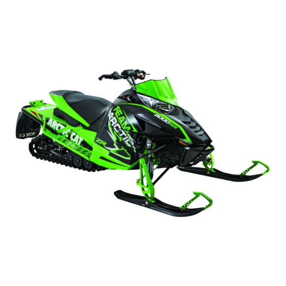
ZR 5000 2015
Service manual
Arctic Cat 2015 ZR 5000 Service Manual
Hide thumbs
Also See for 2015 ZR 5000
:
Operator's manual
(64 pages)
1
2
Table Of Contents
3
4
5
6
7
8
9
10
11
12
13
14
15
16
17
18
19
20
21
22
23
24
25
26
27
28
29
30
31
32
33
34
35
36
37
38
39
40
41
42
43
44
45
46
47
48
49
50
51
52
53
54
55
56
57
58
59
60
61
62
63
64
65
66
67
68
69
70
71
72
73
74
75
76
77
78
79
80
81
82
83
84
85
86
87
88
89
90
91
92
93
94
95
96
97
98
99
100
101
102
103
104
105
106
107
108
109
110
111
112
113
114
115
116
117
118
119
120
121
122
123
124
125
126
127
128
129
130
131
132
133
134
135
136
137
138
139
140
141
142
143
144
145
146
147
148
149
150
151
152
153
154
155
156
157
158
159
160
161
162
163
164
165
166
167
168
169
170
171
172
173
174
175
176
177
178
179
180
181
182
183
184
185
186
187
188
189
190
191
192
193
194
195
196
197
198
199
200
201
202
203
204
205
206
page
of
206
Go
/
206
Contents
Table of Contents
Troubleshooting
Bookmarks
Table of Contents
Table of Contents
General Information
Snowmobile Identification
Recommended Gasoline and Oil
Engine Break-In
Drive Belt Break-In
Genuine Parts
Varying Altitude Operation
Preparation for Storage
Preparation after Storage
After Break-In Checkup/Checklist
Engine Specifications
Electrical Specifications
Drive System Specifications
Drive Clutch/Driven Clutch-Related Specifications
Drive System Components
Chain Case Performance Calibrations
Track Specifications
Suspension Specifications
Torque Conversions
Torque Specifications
Steering and Body
Steering Post
Ski
Ski Wear Bar
Spindle
Steering Tie Rod
Ski Alignment
A-Arms
Ski Shock Absorber
Sway Bar
Front Bumper
Seat Assembly
Seat Cushion
Taillight/Brakelight Assembly
Rear Bumper/Snowflap
Windshield/Console/Headlight
Headlight Bulb
Adjusting Headlight Aim
Engine
Engine Removing Installing - 5000/9000
Engine Removing Installing - 7000
Engine Servicing - 5000/9000
Assembly Schematic - 5000/9000
Engine Servicing - 7000
Assembly Schematic - 7000
Troubleshooting Engine
Engine-Related Items
Water Pump
Pressure Testing Engine
Checking Compression
Testing Oil Pressure
Liquid Cooling System (5000/9000)
Liquid Cooling System (7000)
Cooling System Schematics
Air Silencer (5000)
Air Silencer (7000)
Air Silencer (9000)
Turbocharger/Intercooler (9000)
Fuel Systems
Fuel System
Individual Components
Coolant Temperature Sensor
Fuel Injectors
Self-Diagnostic System/Codes
Fuel Pressure Regulator
Throttle Body Assembly
Throttle Cable
Fuel Filter
Fuel Pump
Troubleshooting
Gas Tank
Electrical Systems
Ignition System
Throttle Position Sensor
Electrical Resistance Tests (5000/9000)
Electrical Resistance Tests (7000)
Voltage Regulator Tests
Testing Fuel Gauge Sender
Emergency Stop Switch
Starter Relay Solenoid
Fuse
Ignition Switch
Starter Motor
Troubleshooting Electric Start
Magneto
Brakelight Switch
Headlight Dimmer Switch
Testing Handlebar Warmer Elements
Testing Thumb Warmer Element
Testing Handlebar Warmer/Thumb Warmer Switch
Testing Passenger Handwarmer Switch
Testing Passenger Handwarmer Elements
Testing Seat Heater Switches
Testing Speedometer Sensor
Testing Gear Position Switch
Testing Shift Switch
Testing Shift Actuator
Voltage/Resistance Chart - Air Temperature
Voltage/Resistance Chart - Coolant Temperature
Drive Train/Track/Brake Systems
Drive Belt
Drive Clutch
Driven Clutch
Drive Clutch/Driven Clutch
Drive Train
Drive Sprockets
Track Tension
Track Alignment
Brake System (Hydraulic)
Changing Brake Fluid
Brake Lever/Master Cylinder Assembly
Troubleshooting Track
Troubleshooting Hydraulic Brake System
Troubleshooting Drive Clutch/Driven Clutch
Suspension
Suspension Setup Basics
Servicing Suspension
Installing Skid Frame
Special Tools
Wiring Diagrams
Advertisement
Quick Links
Download this manual
S E R V I C E M A N U A L
ZR/XF/M/Pantera
5000/7000/9000
www.arcticcat.com
Table of
Contents
Previous
Page
Next
Page
1
2
3
4
5
Advertisement
Table of Contents
Troubleshooting
Troubleshooting Engine
99
Troubleshooting
131
Troubleshooting Electric Start
142
Troubleshooting Track
171
Troubleshooting Drive Clutch/Driven Clutch
172
Need help?
Do you have a question about the 2015 ZR 5000 and is the answer not in the manual?
Ask a question
Questions and answers
Related Manuals for Arctic Cat 2015 ZR 5000
Snowmobiles Arctic Cat ZR 5000 2015 Operator's Manual
(64 pages)
Offroad Vehicle Arctic Cat Pantera 3000 Service Manual
(248 pages)
Offroad Vehicle Arctic Cat ZR 3000 Operator's Manual
(59 pages)
Offroad Vehicle Arctic Cat ZR 6000 R CROSS COUNTRY Operator's Manual
Arctic cat zr 6000 r cross country (108 pages)
Offroad Vehicle Arctic Cat 2015 ZR 7000 Service Manual
(206 pages)
Offroad Vehicle Arctic Cat 2015 ZR 9000 Service Manual
(206 pages)
Offroad Vehicle Arctic Cat ZR 5000 Operator's Manual
(68 pages)
Offroad Vehicle Arctic Cat ZR 8000 Operator's Manual
(68 pages)
Offroad Vehicle Arctic Cat ZR 9000 Operator's Manual
(68 pages)
Offroad Vehicle Arctic Cat Sno Pro 120 2013 Operator's Manual
(61 pages)
Offroad Vehicle Arctic Cat ZR 6000 Operator's Manual
(64 pages)
Offroad Vehicle Arctic Cat XF 7000 Operator's Manual
(64 pages)
Offroad Vehicle Arctic Cat 120 Sno Pro 2011 Operator's Manual
(33 pages)
Offroad Vehicle Arctic Cat ZR 6000 R SNOCROSS 2015 Operator's Manual
(126 pages)
Offroad Vehicle Arctic Cat ZR 120 2017 Service Manual
(62 pages)
Offroad Vehicle Arctic Cat ZR 120 Service Manual
Arctic cat 2014 snowmobile service manual (64 pages)
This manual is also suitable for:
2015 xf 7000
2015 xf 7000 high country
2015 m 7000
2015 m 9000
2015 zr 7000
2015 xf 9000
...
Show all
2015 zr 9000
2015 xf 9000 high country
2015 pantera 7000
Table of Contents
Save PDF
Print
Rename the bookmark
Delete bookmark?
Delete from my manuals?
Login
Sign In
OR
Sign in with Facebook
Sign in with Google
Upload manual
Upload from disk
Upload from URL


Need help?
Do you have a question about the 2015 ZR 5000 and is the answer not in the manual?
Questions and answers