Table of Contents
Advertisement
Advertisement
Table of Contents
Troubleshooting

Subscribe to Our Youtube Channel
Related Manuals for Arctic Cat ZR 120 2017


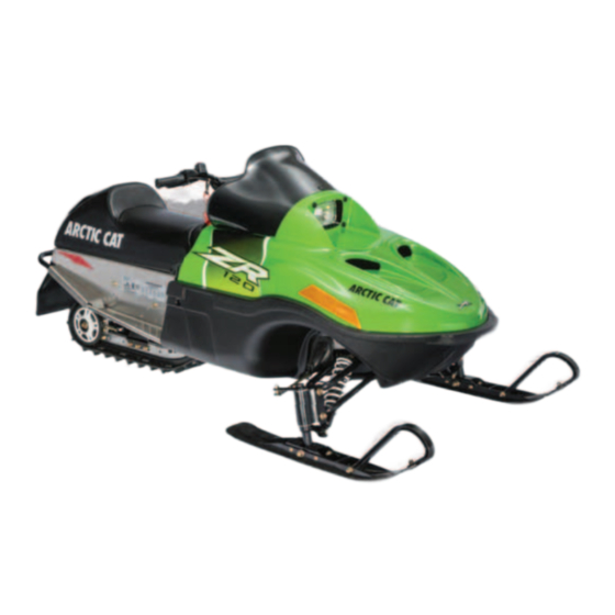
Summary of Contents for Arctic Cat ZR 120 2017
- Page 1 2017 ERVICE ERVICE ANUAL ANUAL ® ® www.arcticcat.com...
-
Page 2: Table Of Contents
2017 ZR 120 Service Manual Table Of Contents General Information/Foreword.......... 2 Electrical System..............33 Snowmobile Identification ..........2 Transistorized Ignition System........33 Recommended Gasoline and Oil........3 Testing Ignition Switches ..........34 Break-In Procedure ............3 Testing Electrical Resistances........34 Genuine Parts............... 3 Drive System..............36 Drive Chain Lubrication .......... -
Page 3: General Information/Foreword
0744-926 These numbers are required to complete warranty claims All materials and specifications are subject to change properly. No warranty will be allowed by Arctic Cat Inc. without notice. if the engine serial number or VIN is removed or muti- Keep this manual accessible in the shop area for refer- lated in any way. -
Page 4: Recommended Gasoline And Oil
Oil break-in. After the 10 hour break-in period, the snowmo- bile may be taken to an authorized Arctic Cat Snowmo- bile dealer for a checkup and oil change at the discretion and expense of the snowmobile owner. -
Page 5: Preparation After Storage
Taking the snowmobile out of storage and correctly pre- 28.6 62.6 96.6 130.6 paring it for operation will assure many miles and hours 29.9 63.9 97.9 131.9 of trouble-free snowmobiling. Arctic Cat recommends the 31.3 65.3 99.3 133.3 following procedure to prepare the snowmobile. 32.6 66.6 100.6 134.6 1. -
Page 6: Torque Specifications
Torque Specifications Torque Item ft-lb Drive System Centrifugal Clutch Secondary Sprocket*** Drive Sprocket Bearing/Chassis* Rear Suspension End Cap/Rail 78 in.-lb Axle Housing/Rail Rear Arm/Bracket* Rear Idler Wheel/Axle* Cross-Brace Axle/Rail* Idler Axle/Tunnel* Steering/Body Outer Tie Rod End/Spindle** Inner Tie Rod End/Steering Post** Ski Shock/Shock Mount A-Arm/Spindle A-Arm/Chassis... -
Page 7: Engine Torque Diagram
NOTE: Before engine assembly, ensure all threaded areas are clean to assure an accurate torque value is achieved. Torque values have a range of ± 20%. = Torque control required = Lubricate with Arctic Cat 4-Stroke Engine Oil = Apply Loctite = Lubricate with Arctic Cat All-Temp Grease 120-ENG10... -
Page 8: Engine Specifications
Engine Specifications Carburetor Specifications Engine Model Number 70CL1-030 Idle Fuel Adjuster Screw Main Jet Pilot Jet Float Height (Turns Out) Displacement 123 cc 77.5 37.5 0.63" No. of Cylinders Bore x Stroke 56 x 50 mm Track Specifications Cooling System Spark Plug (NGK) BPR4ES Spark Plug Gap... -
Page 9: Engine
This engine section has been organized into sub-sections showing a progression for the complete servicing of the Arctic Cat 120 cc engine. For consistency purposes, this section shows a complete and thorough progression; how- ever, for efficiency it may be preferable to remove and disassemble only those components needing to be addressed and to service only those components. -
Page 10: Disassembling
Disassembling 1. Remove the oil drain plug and drain the oil; then install the oil plug and tighten securely. A048 10. Lay the snowmobile on its side. NOTE: A piece of cardboard should be used to pro- tect the finish. 11. - Page 11 IO065A IO068 NOTE: For assembling purposes, note the location NOTE: If the cylinder head will be replaced, the car- of the governor arm spring before removing. buretor studs may be removed by tightening the two nuts against each other; then using a wrench on the 5.
- Page 12 IO071 IO069B 12. Remove the lock nuts and rocker arm pivots securing 16. Using a flywheel puller, remove the flywheel. the rocker arms to the cylinder head. 13. Remove the push rods; then remove the push rod guide plate. IO074 17.
-
Page 13: Servicing Components
22. Note the relation of the connecting rod journal to the crankshaft and mark the connecting rod and end cap for reference during installation; then remove the cap screws and connecting rod end cap. IO077 19. With the piston at TDC, scribe an alignment mark on the gear of the camshaft directly in-line with the alignment dot on the crankshaft gear. - Page 14 CYLINDER HEAD/VALVE ASSEMBLY Measuring Valve Face Width 1. Using a micrometer, measure the width of the valve NOTE: Remove the valves by pressing down on the face. spring retainer and removing the valve keeper. Account for valve springs, spring retainers, and valve keepers.
- Page 15 2. Acceptable width of valve seat contact width (mea- 2. Minimum valve spring free length must not exceed surement A) must be at least 0.03". 1.04". NOTE: With the crankshaft at top dead center on the compression stroke, install the valve springs and spring retainers;...
- Page 16 PISTON ASSEMBLY NOTE: Oversized pistons are available allowing the cylinder to be bored oversized. NOTE: Whenever a piston, rings, or pins are out of tolerance, they must be replaced. Cleaning/Inspecting Piston 1. Using a non-metallic carbon removal tool, remove any carbon buildup from the dome of the piston.
- Page 17 IO085 IO086 3. Piston skirt to cylinder clearance must be within Measuring Piston Pin Bore Diameter 0.0006-0.0016". 1. Insert an inside dial indicator into the piston-pin bore. 4. If the piston/cylinder clearance exceeds the limit, Take two measurements to ensure accuracy. bore the cylinder and use an oversized piston or 2.
- Page 18 2. Check the gasket surface of the cylinder for distor- tion with a straightedge and thickness gauge taking a clearance reading at several places. If the largest reading at any position of the straightedge exceeds the limit, replace the cylinder. 3.
- Page 19 2. Clearance measurement must be within 0.008-0.024". GEN-0039 CRANKSHAFT BEARINGS GEN-0036 MEASURING CRANK PIN/ CONNECTING ROD CLEARANCE 1. Measure the crank pin diameter. Measurement must be at least 1.102". 0744-992 Removing 1. Using a flat-blade screwdriver, carefully work the oil seal from side-to-side out of the crankcase and cover.
-
Page 20: Assembling
2. Inspect the sealing surfaces for trueness by placing NOTE: Coat the cylinder wall, connecting rod bear- each on the surface plate covered with #400 grit wet- ing surface, and the crankshaft with engine oil. or-dry sandpaper. Using light pressure, move both 2. - Page 21 IO080A IO101 5. Apply lightweight oil to the tappets; then install the NOTE: When installing the governor control shaft, tappets to the proper guides as noted during disas- position the shaft so the flat end (A) of the shaft is sembly.
- Page 22 9. Secure the crankcase side cover to the crankcase 14. Install the air shroud to the cylinder head and secure with the cap screws. Tighten to 16 ft-lb using the fol- the shroud with cap screw. Tighten to 96 in.-lb. lowing pattern.
- Page 23 IO097A IO100A 23. Install the throttle cable mounting bracket and secure NOTE: Route the stator harness through the slot in the bracket with two cap screws to the crankcase. the crankcase above the flywheel. Tighten to 120 in.-lb. 19. With the flywheel key in the crankshaft, install the flywheel and starter pulley;...
-
Page 24: Installing
IO065A IO064A 28. Install the retaining plate and fitting; then secure the NOTE: When securing the governor control shaft air cleaner cover to the air cleaner case with the two (A), turn it clockwise until it stops; then tighten the screws. -
Page 25: Changing Oil
9. Install the tie rods on the steering post; then secure with lock nuts (threads coated with green Loctite #609) and washers. Tighten to 20 ft-lb. 10. Place the steering post in position in the lower steer- ing post bearing and on the steering post support. IO106A 14. -
Page 26: Recoil Starter
4. Mark the ratchet arms (E) for assembling purposes; then remove the ratchets and account for the friction Recoil Starter spring (F). NOTE: The ratchet arms must be installed in their respective positions. 5. Slowly remove the reel. Account for the spiral spring (G). -
Page 27: Troubleshooting Engine
Troubleshooting Engine Problem: Engine Does Not Start (No Spark at Spark Plug) Condition Remedy 1. Ground connections dirty — loose 1. Check all ground connections — clean and tight 2. Wiring harness shorting — disconnected 2. Repair — replace — connect wiring harness 3. -
Page 28: Fuel System
REMOVING Fuel System NOTE: Before removing the carburetor, be sure the gas tank shut-off valve is in the OFF position. 1. Remove the screws securing the air cleaner cover to the air cleaner case and account for the filter and This section has been organized for servicing the fuel retaining plate. - Page 29 CLEANING CAUTION DO NOT place any non-metallic components in parts- cleaning solvent or carburetor cleaner because damage or deterioration will result. 1. Place all metallic components in a wire basket and submerge in carburetor cleaner. 2. Soak for approximately 30 minutes; then rinse with fresh parts-cleaning solvent.
- Page 30 1. Install the nozzle (H) and main jet (G) into the carbu- retor tower. 2. Place the needle jet assembly (F) and the float (E) into position and secure to the carburetor body with the float pin (D). 3. Secure the float chamber w/rubber gasket to the car- buretor with the cap screw (C).
-
Page 31: Throttle Cable
0744-922 A979 2. Pull all slack from the throttle cable wire and exert 2. Disconnect the throttle cable from the lever; then slight tension on the wire. slide the cable out of the lever. 3. Tighten the throttle cable jam nuts. ! WARNING DO NOT operate the snowmobile when any component in the throttle system is damaged, frayed, kinked, worn,... - Page 32 NOTE: Note the location of the cable tie for assem- 2. Seat the cable drum into the throttle lever recess; then secure the throttle lever to the throttle control bly. with a pin and C-clip. 5. Rotate the throttle cable lever of the governor control arm to the wide-open position and route the cable end out of the arm;...
-
Page 33: Troubleshooting Fuel System
Troubleshooting Fuel System Problem: Carburetor Too Rich (0-1/4 Opening) Condition Remedy 1. Choke valve will not seat 1. Adjust — service — replace choke cable — assembly 2. Idle fuel adjuster screw out of adjustment 2. Adjust idle fuel adjuster screw 3. -
Page 34: Electrical System
As the flywheel turns faster, the primary current increases, and the terminal voltage of the circuit consist- Electrical System ing of the resistor (R) and the transistor (TR1) increases. This increases the working voltage at the connection of the series circuit (r1 + r2) connected in parallel to the pri- mary circuit. -
Page 35: Testing Ignition Switches
Testing Ignition Switches 1. Disconnect the engine wires from the main wiring harness. 2. At the main wiring harness engine connector, connect the red tester lead to the violet wire; then connect the black tester lead to the engine ground (brown wire). 3. - Page 36 1. Open the hood; then disconnect the handlebar warmer two-wire connector. 2. Connect one ohmmeter lead to the green/white lead; then connect the other ohmmeter lead to the yellow lead. YM-145 3. With the handwarmer toggle in the ON position, con- nect one ohmmeter lead to pin and the other ohmme- ter lead to pin.
-
Page 37: Drive System
Drive System Drive Chain and Sprockets REMOVING 1. Remove the self-tapping screws securing the front clutch shield and rear sprocket cover; then remove from the engine compartment. Note the position of IO112A the hood cable. 6. Secure the centrifugal clutch with a pair of channel- lock pliers at the outer clutch collar;... -
Page 38: Track And Driveshaft
6. Inspect the driveshaft sprockets for wear or damage. 6. Place the muffler into position in the engine com- partment; then press down on the muffler and posi- INSTALLING tion the flange onto the engine exhaust studs. Secure with two nuts and the hold-down spring. 1. - Page 39 INSTALLING 1. Spacer 2. Carriage Bolt 3. Bearing 4. Track Drive Assy 5. Drive Sprockets 6. Driveshaft 7. Key 8. Chain Sprocket 9. Lock Nut 10. Cap Screw 11. Washer 12. Chain IO115A 5. Remove the four lock nuts securing the drive 742-425A sprocket bearings to the tunnel;...
- Page 40 Excessive wear to the idler wheels, drive lugs, and track will occur if the track is improperly aligned. Arctic Cat recommends that the track alignment be checked once a week or whenever the track tension is adjusted.
-
Page 41: Brake System
2. Position the tips of the skis against a wall; then using 3. After proper track alignment is obtained, tighten both a shielded safety stand, raise the rear of the snowmo- the adjusting bolt jam nut and the idler wheel cap bile off the floor making sure the track is free to screw securely. - Page 42 4. Remove the brake band from the engine compart- ment. 5. Remove the C-clip securing the brake lever pin in the brake housing; then remove the pin and lever. A999 A998 6. Disconnect the brake cable from the lever; then slide the brake cable out of the lever.
-
Page 43: Troubleshooting Track
3. If travel distance is not as specified, adjust the brake. ADJUSTING BRAKE LEVER TRAVEL A005 6. Secure the brake cable to the steering post with a cable tie; then install the handlebar pad. 735-457A 7. Install the hood cable and the front clutch shield. 1. -
Page 45: Rear Suspension
This section has been organized so each procedure can be completed individually and efficiently. The technician Rear Suspension should use discretion and sound judgment when removing and installing components. GENERAL INFORMATION Removing Skid Frame Quick acceleration and the ability to go through the turns with power are the most important handling qualities. -
Page 46: Wear Strip
NOTE: A wear strip can be removed and installed without removing the skid frame. To do this, remove the machine screw and lock nut securing the wear strip at the front of the slide rail; then align the wear strip with openings (windows) in the track and drive it rearward off the slide rail. -
Page 47: Rear Suspension Arm/Rear Springs
INSPECTING 1. Inspect all rear arm weldments for cracks or unusual bends. 2. Inspect all tubing for cracks or unusual bends. 3. Inspect the axles for wear or damage. 4. Inspect the upper and lower bearings for wear or damage. 5. -
Page 48: Upper Idler Wheels
ASSEMBLING 1. In order, slide the axle through the rear axle housing; Slide Rail then place a spacer on the axle. Slide the axle through the opposite axle housing. 2. Place the adjuster bushings on the axle (on the out- side of each axle housing). - Page 49 AO160 0743-189 3. Remove the cap screw securing the rear suspension INSTALLING arm to the support bracket. 1. Install the rear axle housing and adjuster bushing; 4. Remove the cap screws and lock nuts securing the then secure with cap screws and lock nuts. Tighten to rear suspension arm support bracket.
-
Page 50: Installing Skid Frame
6. Place the snowmobile in the upright position. 7. Securely tighten all mounting hardware (from steps 3 and 4) to 20 ft-lb. 8. Check track tension; adjust as necessary (see Track and Driveshaft section). Steering and Body Steering Post AO160 6. - Page 51 7. Using a solvent, clean the old adhesive from the han- dlebar. 8. Loosen the screw securing the emergency stop switch to the handlebar; then remove the stop switch. 9. Remove the two cap screws and lock nuts securing the upper steering post bearing retainer; then remove the retainer and bearing.
- Page 52 INSTALLING A026 NOTE: Check all fasteners to ensure they are tight. Turn the handlebar full-left and full-right several times to ensure free movement. 6. Apply Handlebar Adhesive to the bore of the handle- 1. Steering Post 11. Pad Cover 22.
-
Page 53: Ski
Arctic Cat recommends that the ski wear bars be checked once a week and replaced if worn to 1/2 of original diameter. -
Page 54: Tie Rods
2. Center the wear bar studs in the holes and install the lock nuts. Tighten lock nuts securely. Tie Rods REMOVING AND DISASSEMBLING 1. Remove the tie rod from the spindle. ZJ296A NOTE: The ball joint must be installed on the bot- tom side of the spindle arm. -
Page 55: Ski Alignment
IO119A IO119B 5. Remove the two cap screws and lock nuts securing 2. Place the tie-rod ball joint into position on the bottom the spindle to the suspension arms. Account for all side of the spindle arm and secure with a lock nut mounting hardware. -
Page 56: Front Suspension A-Arms
2. Measure the distances to the inside edges of the skis in two places. Make sure the measurements are taken behind the spindle mount and ahead of the spindle mount. AO167 4. Remove the lock nuts securing the A-arms to the chassis;... -
Page 57: Front Suspension (Ski) Shock Absorber
INSTALLING 2. Remove the two cap screws securing the belly pan to the front end; then account for washers and lock washers. 1. Upper A-Arm 2. Lower A-Arm 3. Axle 4. Axle 5. Axle 6. Cap Screw 7. Cap Screw 8. -
Page 58: Seat/Cushion/Taillight Housing
2. Inspect the two belly pan threaded bosses and ensure 5. Remove the knot at the handle and remove the han- they are in good shape. dle; then thread the rope through the bushing in the console. INSTALLING 6. Turn the gas tank shut-off valve to the CLOSED 1. -
Page 59: Headlight Assembly
5. Untie the slip-knot at the starter case and allow it to slowly rewind into the case. 6. Slide the choke cable through the console and secure with two lock nuts; then using a screw (coated with blue Loctite #243), secure the choke knob to the end of the cable. -
Page 60: Wiring Diagram
Wiring Diagram 0750-506... - Page 61 NOTES...
- Page 62 Printed in U.S.A. Trademarks of Arctic Cat Inc., Thief River Falls, MN 56701 p/n 2261-697...
Need help?
Do you have a question about the ZR 120 2017 and is the answer not in the manual?
Questions and answers