Advertisement
Table of Contents
- 1 Table of Contents
- 2 Chapter 1 Introduction
- 3 Chapter 2 Safty
- 4 Chapter 3 Equipment Description and Component Identification
- 5 Introduction - - - - - - - - - - - - - - - - - - - - - - - - - -
- 6 Chapter 4 Installation
- 7 Chapter 5 Ink Jet Printer Operation
- 8 Chapter 6 Maintenance
- 9 Chapter 7 Troubleshooting
- Download this manual
Advertisement
Table of Contents

Summary of Contents for Saturn S300 Series
-
Page 2: Table Of Contents
Contents CONTENTS Chapter 1 Introduction………………………………………………………1-5 Chapter 2 Safty ………………………………………………………………2-1 Chapter 3 Equipment Description and Component Identification…3-1 Chapter 4 Installation ………………………………………………………4-1 Chapter 5 Ink Jet Printer Operation ………………………………………5-1 Chapter 6 Maintenance ……………………………………………………6-1 Chapter 7 Troubleshooting …………………………………………………7-1 Appendix: 1. Hydraulic System Connecting Figure …………………………8-1 2. -
Page 3: Chapter 1 Introduction
Introduction Introduction In this chapter you will find: a brief description of the intended use of the machine who this manual is intended for, how it is organized, and the writing conventions that are used to present information an introduction to each of the chapters in this manual WARNING: Read chapter 2, Safety, before attempting to service operate the equipment. - Page 4 Introduction Chapter 1 Contents Introduction - - - - - - - - - - - - - - - - - - - - - - - - - - 1-3 References to the S400 serials printer - - - - - - - 1-3 Printers Supplies - - - - - - - - - - - - - - - - - - - - - -1-3 Who Should Use this Manual? - - - - - - - - - - - - - - - - - 1-4 Writing Conventions Used In this Manual - - - - - - - - - - - - 1-5...
- Page 5 S300/400 Printer Manual. Printer Supplies Due to the large variety of SATURN Inks available for use with this product, this printer can print on virtually any surface, texture, contour or shape. Contact your SATURN sales representative or distributor if you have any question regarding supplies selection (inks, make-up fluids and cleaning solutions) or product application.
- Page 6 Introduction Who Should Use this Manual? This Manual is intended for use by SATURN service personnel Introduction and those customers who are qualified to perform their own printer service and maintenance. WARNING: Customers who intended to service and maintain the...
-
Page 7: Chapter 2 Safty
Introduction Service Manual Overview Chapter 2, Safety This chapter contains important equipment and safety guidelines, as well as the safety writing conventions used throughout the manual. Chapter 3, Equipment Description and Component Identification This chapter shows the location and provides a brief description of each of the main components in the printhead, the hydraulic and electronic compartments of the printer. - Page 8 Safety Safety In this chapter you will find: important safety guidelines to follow when operating the equipment important safety guidelines to follow when working with inks, make-up fluids, and cleaning solutions important safety guidelines to follow when long-term shutdown printhead cleaning shutdown without cleaning recovery tube cleaning WARNING: Read this chapter thoroughly before attempting...
- Page 9 Safety Chapter 2 Contents Introduction - - - - - - - - - - - - - - - - - - - - - - - - - -2-3 Safety Terms - - - - - - - - - - - - - - - - - - - - - - - - - - - 2-4 Fire Prevention Statements- - - - - - - - - - - - - - - - -2-4 Danger Statements - - - - - - - - - - - - - - - - - - - -2-4 Warning Statements - - - - - - - - - - - - - - - - - - - 2-4...
- Page 10 Safety Introduction The policy of Saturn Technologies Ltd. is to manufacture non-contact printing/coding systems and ink supplies which meet high standards of performance and reliability. We enforce strict quality control techniques to eliminate the potential defects and hazards in our products.
- Page 11 Safety Safety Conventions Used in this Manual Fire prevention statement The ink and make-up fluid are both flammable and may cause fire. Please keep any fire five meters away from the printer, and set up the printer in dry environment Danger Statements Danger statements: are used to indicate immediate hazards which WILL result in...
- Page 12 Safety Equipment Safety Guidelines WARNING: Always observe the following safety guidelines when installing, operating, servicing, or maintaining the printer and associated equipment. Comply with Electrical Codes Shutdown the power before opening printer door; Do not insert tweezers, screw driver or any steel material into ink ejection hole at the end of printhead.
- Page 13 Ground the Service Tray Ground the Saturn service tray to the printer, and install the printhead into the service tray when test printing or dumping ink from the printhead. This is necessary to avoid the possibility of...
- Page 14 Safety Ink and Make-up Fluid Caution Items 1. Ink and make-up replenishment While the printer is operated, the ink and make-up are automatically transferred at fixed intervals from the ink or make-up tank to the main ink supply pipe for replenishment purposes. If the ink or make-up sufficiency alarm is issued, add ink or make-up to the tank within 60 minutes.
- Page 15 Safety Long-term Shutdown Guidelines Please refer to the procedure of "auto flush" in the system maintenance. Long-term shutdown requires that you drain out the ink from the printer and flush the ink system. This is necessary, as left ink in the system will dry/solidify, causing problems when re-commissioning the printer. Cleaning of Print Head Most of ink used in printer is fast dry ink.
- Page 16 Safety Shutdown without Auto Flush Print Key Press the for 2 seconds, the printer will start to shutdown with a "system cleaning”. Using this shutdown frequently in a short period of time will cause surplus adding of make-up to the system.
- Page 18 Safety Recovery Tube Cleaning If the printer is running for a long time without auto flush, the recovery tube may accumulate some ink and will need to be cleaned. Caution: Do not perform recovery tube cleaning more than twice. 2-10...
-
Page 19: Chapter 3 Equipment Description And Component Identification
Equipment Description and Component Identification Equipment Description and Component Identification In this chapter you will find: a brief description of the two main printer assemblies --- the control unit and the printhead the location and a brief description of the function of the main components in the hydraulic, and electronic compartments of the printer, as well as the printhead Turn to page 3-2 for a chapter-level Table of Contents. -
Page 20: Introduction - - - - - - - - - - - - - - - - - - - - - - - - - -
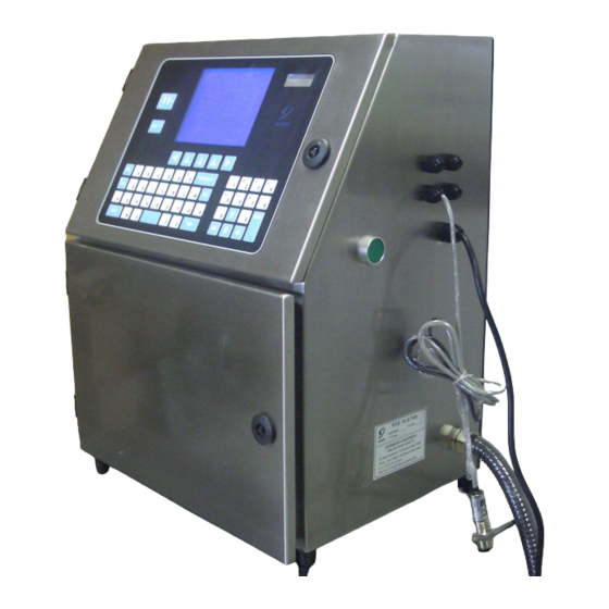
Equipment Description and Component Identification Chapter 3 Contents Equipment Description- - - - - - - - - - - - - - - - - - - - - - - - - - - - - - - 3-3 Introduction - - - - - - - - - - - - - - - - - - - - - - - - - - 3-3 Control Unit- - - - - - - - - - - - - - - - - - - - - - - - - - 3-4 Hydraulic Compartments - - - - - - - - - - - - - - - - - - - - - 3-4... - Page 21 Equipment Description and Component Identification Introduction The S400 Series printer is comprised of two basic assemblies -- the control unit and the printhead -- connected by an umbilical assembly (a flexible conduit containing electrical and fluid lines). Refer to Figure 3-1. Figure 3-1.
- Page 22 Equipment Description and Component Identification Control Unit The control unit consists of the hydraulic and electronic compartments of the printer, as well as the keyboard (Refer to Figure 3-2). Hydraulics Compartment The hydraulics compartment is located behind the front (Fluid pan) door of the control unit (refer to Figure 3-2).
- Page 23 Equipment Description and Component Identification Electronic Compartments Electronic compartments are set in the upper door (refer to Figure 3-2). The main function is to control all the electronic signal. For more information Refer to Electronic Components on page 3-16 for information on the main components found in the electronic compartment.
- Page 24 Equipment Description and Component Identification The Printhead The printhead is connected to the control unit by the umbilical assembly. The printhead receives pressurized ink through the umbilical, and turns the ink stream into tiny electrically charged ink droplets which are deflected onto a substrate to form a printed code.
- Page 25 Equipment Description and Component Identification Component Identification Introduction This section identifies the location and describes the function of the main components included in the hydraulic, pneumatic, and electronic compartments of the control unit, as well as the main components in the printhead. Only main printer components are covered in this section.
- Page 26 Equipment Description and Component Identification Ink Pressure Gauge Viscosimeter Makeup Pouring Orifice Ink Pouring Orifice Ink Pressure Regulator Makeup Tank Ink Tank Support Tray Figure 3-5. Hydraulics Compartment-1 (with support tray pulled out) Ink Pressure Gauge The ink pressure gauge indicates the amount of air pressure (in psi and bar) applied to the ink supply cylinder.
- Page 27 Equipment Description and Component Identification Ink Tank The ink tank stores fresh ink for printer. Makeup Tank The Makeup tank stores Makeup and adds Makeup to the ink when ink becomes too dense. Support Tray The support tray carries the whole hydraulic system, ink and Makeup tank, which can be pulled out in order to check the hydraulic system.
- Page 28 Equipment Description and Component Identification Solenoid Electric Valves Makeup Valves Board Filter Recovery Filter Churn Filter Main Ink Filter 11 Ink Supply Pump 12 Makeup Pump 13 Circulation Pump 14 Recovery Pump Figure 3-6. Hydraulics Compartment-2 11. Ink Supply Pump The ink supply pump transfers ink to printhead and generates a pressure to spurt out the ink through printhead.
- Page 29 Equipment Description and Component Identification Figure 3-7 Hydraulic System 3-11...
- Page 30 Equipment Description and Component Identification Figure 3-8 Perspective Drawing for Valves Board 3-12...
- Page 31 Equipment Description and Component Identification 15. Electric Solenoid Valve Assembly The Electric Solenoid valve assembly distributes positive pressure and vacuum to each connector and Electric Solenoid valve. (Figure 3-8) 16. Ink Supply Electric Solenoid Valve Turn on the ink supply Electric Solenoid valve and then the ink in the ink supply pump and the main ink filter is able to reach ink pressure gauge and printhead.
- Page 32 Equipment Description and Component Identification Electronic Components Refer to Figure 3-10 for the location of the main electronic components, and refer to the following pages to find a brief description of the function of the components. Caution: To access this compartment, use the keys and/or the hex key (supplied with the printer) to open the cabinet door.
- Page 33 Equipment Description and Component Identification 23. Ink Control Unit(ICU) ICU receives data from edit control unit and completes the control of ink circulation, ink level and viscosity inspection. 24. Print Control Unit(PCU) PCU receives data from edit control unit to control print signal (step wave, sine wave, high voltage, etc.) and return data to edit control unit.
- Page 34 Equipment Description and Component Identification Printhead Components Refer to Figure 3-11 for the location of the main printhead components, and refer to the following pages to find a brief description of the function of the components. 40. Charging Electrode 45. High Voltage Deflection Electrode 41.
- Page 35 Equipment Description and Component Identification 42. Solenoid (Ink Supply, Cleaning Solenoid) Attached to the rear of the nozzle, the solenoid controls the flow of pressurized ink to the nozzle. The Solenoid opens at40psi (2.8 bar) of ink pressure. 43. Nozzle The nozzle is an assembly which houses a jeweled orifice and a piezo-electric crystal used to change the ink stream into ink droplets.
-
Page 36: Chapter 4 Installation
Installation Installation In this chapter you will find: Site preparation requirements Procedures for unpacking and assembly Encoder and Photocell set-up procedures Turn to page 4-2 for a chapter-level Table of Contents. - Page 37 Installation Chapter 4 Contents Introduction - - - - - - - - - - - - - - - - - - - - - - - - - - - - - - - - - - - - - - -4-3 Site Preparation - - - - - - - - - - - - - - - - - - - - - - - - - - - - - - - - - - - - 4-4 Determine Printer Location - - - - - - - - - - - - - - - - - - - - - - - -4-4 Electrical Requirements - - - - - - - - - - - - - - - - - - - - - - - - - - 4-4...
- Page 38 Installation Introduction This chapter guides you through the recommended procedures to install the printer. Proceed through the sections in this chapter in the order shown below: Site Preparation - - - - - - - - - - - - - - - - - - turn to page 4-4 Unpack and Inspect the Printer - - - - - - turn to page 4-5 Assemble the Printhead Stand - - - - - - - turn to page 4-6 IOU Board Connections - - - - - - - - - turn to page 4-7...
- Page 39 Installation Site Preparation Determine Printer Position the printer near the conveyor. Consider the following Location guidelines: The area selected should be free of vibration. Make certain that the print head can reach the conveyor and there is some space left for operator to disassembly and clean the print head.
- Page 40 Remove the printer from its carton and visually inspect it for its Carton damage. Examine the control unit, umbilical, and printhead closely. The printer is packed carefully at the SATURN manufacturing facility. If any damage is noted, file damage claims with the carrier. Connect Electrical The printer is available at 110/220 VAC.
- Page 41 Installation Assemble the Printhead Stand Unpack and Assemble Follow the installation instructions included with the printhead stand. the Printerhead Stand Bolt the Printerhead Once you have determined the final location of the printhead Stand to the Floor stand, bolt the stand to the floor. Figure 4-1.
- Page 42 Installation IOU Board Connector’s Definition and Encoder and Photocell Installation Follow these steps to connect the Photocell: Connect the Photocell WARNING: The printer must be power off when installing the Photocell. Route the photocell wires through one of the side ports on the printer.
- Page 43 Installation X4 connector (Input) X3 connector (Output) Figure 4-2. Pin identification of IOU board...
- Page 44 (2) The encoder must be used with FCU. Because most of the production line are moving at the same speed, the encoder and FCU are selected spare parts, ordered from Saturn. For standard S480 model, FCU has already been set inside.
- Page 45 Installation 1.Open the upper door, you will see: there is a blank area with the white letters of FCU in the centre of IOU. 2.Turn off the power, and plug the FCU in the IOU, refer to the picture below about the plugging direction.
- Page 46 Installation +V (Positive of Supplied Power) is “red” wire; The color of OMRON encoder: 5 to 24VDC(Positive of Supplied Power) is “Brown” wire; A(Signal A) is “Green” wire; ONT A(Signal A) is “Black” wire; 0V (Negative of Supplied Power) is “Black” wire. 0V(Negative of Supplied Power) is “Blue”...
- Page 47 The setting steps are listed as followed: Enter <Print Setup-3>, select <Encoder Setup>. It displays as below: Setup Encoder Status: Printer is enable to 2007/ 12 / 3 12:00 Saturn Technologies Co. Ltd Encoder Status Frequency Divide (1~31) Frequency Multiple (1~31)
- Page 48 Installation 1. Enter <Print Setup-3>, select <Length Counter>. If you can not select Length Counter, please check the setup of FCU (Refer to the CAUTION of figure 4-7 in Chapter 4) 2. If the FCU is set correctly, the screen will display like this: Setup Encoder System Status Printer is off...
- Page 49 Installation Status: Insert Serial Number Printer is off 2007 / 12 / 13 12:00 2007 / 12/ 13 12 : 24 : 36 0013 Leading Zeros Name Start Step Size Repeat Count 9999 Current Value Exit (F3) Ok (F1) Cancel (F2) Current Flow Time: 4200 There is a select box Illuminated in the “Parameter Setup Zone”.
- Page 50 Installation CAUTION: The name of the serial number is built up by the system, and it cannot be changed by yourself.; If you enter wrong setting during parameter setup, press <Cancel> to come back to the old value, and then enter the new setting again.
- Page 51 Installation Cable, wire, and construction material manufacturers usually require printing from the first meter at any time, but this requirement is random and unpredictable. When deciding reset serial number to 1, resetting serial number too many times may cause miss opportunity to reset. Therefore, S420 Serial printer add a special function as “Quick Reset Serial Number”.
- Page 52 The following are essential for proper printer set-up: SATURN ink Tools and Supplies Needed SATURN make-up fluid Wash Pan (Service Tray) Printhead Holder & Thumb Screw Magnifier Glass Selection of hand tools Flush the system and...
-
Page 53: Chapter 5 Ink Jet Printer Operation
INK JET PRINTER OPERATION Ink Jet Printer Operation In this chapter you will find how to operate the printer to meet production demand. Turn to page 5-2 for a chapter-level Table of Contents. - Page 54 INK JET PRINTER OPERATION Chapter 5 Contents I n t r o d u c t i o n - - - - - - - - - - - - - - - - - - - - 5 - 4 Menu Organization - - - - - - - - - - - - - - - - - - - - - - 5-4 Keyboard Description - - - - - - - - - - - - - - - - - - - - - - 5-5 Ink Jet Printer Operation - - - -- - - - - - - - - - - - - 5-9...
- Page 55 INK JET PRINTER OPERATION Software Version - - - - - - - - - - - - - - - - - - - - 5-36 Machine ID - - - - - - - - - - - - - - - - - - - - 5-36 System Maintenance - - - - - - - - - - - - - - - - - - - - - 5-37 Ink(On/Off) - - - - - - - - - - - - - - - - - - - - - 5-37 H.V.(On/Off) - - - - - - - - - - - - - - - - - - - - - 5-37...
- Page 56 INK JET PRINTER OPERATION Menu Organization...
- Page 57 INK JET PRINTER OPERATION Keyboard Description Display Screen Ink Jet Right Adjust Keys Function Print Select Key Display Screen Display organization as following: System Status Menu Name Zone Main Menu -1 System Status: Printer is off 2007 / 12 / 13 10:26 Message Edit Zone Inkjet Printer.
- Page 58 INK JET PRINTER OPERATION System Status Zone Displays the current status of the machine like “Printer is off”, “Printer is starting up”, “Printer is shutting down”, “Printer is ready”, “Printer is ready to print” etc. Menu Name Displays the menu name or function name in the current menu, such as “Main Menu –...
- Page 59 INK JET PRINTER OPERATION Keyboard INK JET KEY Power Supply (Green LED) System Status (Green LED) Warning Status (Yellow LED) Fault Status (Red LED) INK JET KEY Press INK JET KEY for 2 seconds to start or turn off the printer. Do not switch off the printer by using the main power switch or unplugging the power supply until the printer displays "printer off"...
- Page 60 INK JET PRINTER OPERATION General Key Directions Key Used to move the cursor in the LCD screen. Adjust Key Used to move the function options left or right if the number of the options is over three. In certain function options, which is used to adjust parameter setup change...
- Page 61 INK JET PRINTER OPERATION Ink Jet Printer Operation Printer Startup Procedure Press the “Power Supply Switch” at the right side of cabinet. About 2 seconds later “Printer is off” will be displayed on the “System Status Zone” at LCD screen. Printer is ready to startup.
- Page 62 INK JET PRINTER OPERATION Message Edit Clear Message If there is a message on the “Message Edit Zone”, you can select this function to clear the old message in order to edit a new one. Print Message When you have finished editing message, select “Print Message” to confirm the content of printing.
- Page 63 INK JET PRINTER OPERATION Insert Clock The printer can print real time, including year, month, date, hour, minute, second. And the time can be offset by days or hours when you want to print the expiry time. The procedure of “Insert Clock” as following: Enter <Message Edit-2>, select <Insert Clock>...
- Page 64 INK JET PRINTER OPERATION <Insert Clock>, set up the formats or the offset time of the clock again and the changed clock information you setup will be displayed in the “Message Edit Zone”. Insert Serial Number Caution: Two serial numbers can be inserted at most. The procedures of “Insert Serial Number”...
- Page 65 INK JET PRINTER OPERATION Reset Serial Number This function is only to change the current value of serial number, cannot change other parameter of the serial number. The steps of resetting serial number are as below; 1. Enter<Edit Message-2>, select <Reset Serial Number>, it displays as below: Restore Serial Number Status:...
- Page 66 INK JET PRINTER OPERATION Shift Code Caution: The shift code can be changed according to the time or the print counter. The procedures of “Insert Shift Code” as below: Enter <Edit Message-3>, select <Shift Code>, it displays as below: Shift Code Status: Printer is ready 2007 / 12 / 13 12:00...
- Page 67 INK JET PRINTER OPERATION Insert Message When editing new message, it can insert the messages which already have been saved at printer system. The procedures of “Insert Message” as below: Enter <Edit Message-3>, select <Insert Message>, it displays as below: Insert Message Status: Printer is ready...
- Page 68 INK JET PRINTER OPERATION Insert 2D Code Caution:2D Code can be various according to the changing of system time and serial number. The procedures are as follow: 1. Enter <Message-4>, it displays as below: Select “2D Code”, it displays as below: 3.
- Page 69 INK JET PRINTER OPERATION Select <OK> to insert 2D code. It will display in the Message Edit Zone. Caution:If wrong parameter input, select <Cancel> to reset the parameter. Caution:If changing the inputted parameter, move the cursor to cover the original 2D Code, then enter <Message Edit-4>, select “2D Code”...
- Page 70 INK JET PRINTER OPERATION 3. Use up or down <Direction key> to move the select box to the message you needed, setup each parameter. Input “String length” directly, and no need to adjust other parameter. 4. Select “OK” to insert serial random number. It will display in the Message Edition Zone (It displays disordered bits at first).
- Page 71 “*”. Therefore, do not stop printing when connecting with PC. 2. The software for generating serial random number is developed by customers, according to their printing needs. Saturn only supplies the testing software for connecting and telecommunication protocols between PC and inkjet printer.
- Page 72 Message” as below: Enter <Message Store-1>, press <Select Message>, it displays as below: Select Message Status: Printer is ready 2007 / 12 / 13 12:00 Saturn Technologies Co. Ltd Message Name Height Width TEST Ok (F1) Exit (F3) Current Flow Time: 4200 It displays all the saved messages in the “Parameter Setup Zone”...
- Page 73 INK JET PRINTER OPERATION Save Message Save As After editing message, setup all the print parameters (Print Delay, Message Width, Message Height etc.) to meet the current production demand, then you can save the contents of message and the current print parameter.
- Page 74 Enter <Message Store-2>, select <Delete message>, it displays as below: Delete Message Status: Printer is ready 2007 / 12 / 13 12:00 Saturn Technologies Co. Ltd Message Name Height Width Sample 1 Sample 2 Sample 3 Ok (F1)
- Page 75 1. Insert the U disk which has some qualified messages into the USB port on ECU board. 2. Enter< Message Store-2>, select <Download Message>, it displays as below: Download Message Status: Printer is ready 2007 / 12 / 13 12:00 Saturn Technologies Co. Ltd Message Name Height Width CRXX SCXX XZXX Exit...
- Page 76 1. Connect USB memory disc to the USB port of the ECU board. 2. Enter< Message Store-2>, select <Upload Message>, it displays as below: Download Message Status: Printer is ready 2007 / 12 / 13 12:00 Saturn Technologies Co. Ltd Message Name Height Width CRXX CRXX XZXX...
- Page 77 “Printer is reading USB file”, “Saving data”, “Printer is off” will be displayed successively on the “System Status Zone” of the screen. Program Update Status: Printer is ready 2007 / 12 / 13 12:00 Saturn Technologies Co. Ltd File Name File Size Modified Date CRXX 07-12-13 10:51 CRXX...
- Page 78 5. Power on the printer again to finish the upgrade procedure. Fonts Operation Install Multi-language Fonts Authorized by Saturn, Chinese language fonts can be installed in the printer. 1. Stop the ink stream, to the status of “Print is off”.
- Page 79 6. Press <OK> to confirm the fonts have been saved in USB memory disc. User-defined Fonts Under the authority of Saturn, you may edit (user-defined) fonts, and you may take the procedure in the training course as a reference. Download Fonts 1.
- Page 80 INK JET PRINTER OPERATION 6. Press <Ok> to confirm the fonts have been saved in U disc. Caution:The fonts in the U disc must be Saturn Standard (.FON), and the name of the fonts should not beyond 8 characters of English letter or number (should not as the same as the name that has existed in printer), otherwise, printer can not distinct.
- Page 81 The procedures as below: Enter <Print Setup-1>, select <Print Delay>, it displays as below: Print Delay Status: Printer is ready 2007 / 12 / 13 12:00 Saturn Co. Ltd Product Detect Print Delay (0~32000) Print Interval Exit Cancel Current Flow Time: 4200 Use right or left <Adjust Key>...
- Page 82 INK JET PRINTER OPERATION Caution: “print interval” is used to filtrate the useless pulse of product detector and avoid wrong printing. Message Width It is used to adjust the width of the printed message on the products when the encoder status is off (see “Encoder Setup”). The higher the setup value is, the narrower the width of the message (the same product moving speed).
- Page 83 The procedures of “print repeat” setup as below: Enter <Print Setup-2>, select <Print Repeat>, it displays as below: Print Repeat Status: Printer is ready 2007 / 12 / 13 12:00 Saturn Technologies Co. Ltd Repeat Mode Single time Repeat Pitch Repeat Count Ok (F1) Cancel (F2)
- Page 84 Enter <Print Setup-2>, select <Message INV/REV>, it displays as below: Message Inv / Rev Status: Printer is ready 2007 / 12 / 13 12:00 Saturn Technologies Co. Ltd Message Reverse ABCD Message Invert ABCD Exit Current Flow Time: 4200 Use up/down <Direction Key>...
- Page 85 “Message Edit Zone”. The procedures as below: Enter <Print Setup-3>, select <Product Counter>, it displays as below: Product Counter Status: Printer is ready 2007 / 12 / 13 12:00 Saturn Technologies Co. Ltd Display the Counter Printed numbers Products Detected 3524 Products Printed 104756...
- Page 86 Length Counter Parameter: it is for setting the printing intervals (to print once in a certain interval of length or products), please consult the engineers of Saturn. Caution: Under the status of “Printer is ready to print”, length counter’s setting is locked and cannot be changed. Press “Print” and exit the status of “Printer is ready to print”, you may set up...
- Page 87 It is used to adjust the main clock of the printer. The setup procedures as below: Enter<System Setup-1>, select <System Clock>, it displays as below: System Clock Status: Printer is ready 2007 / 12 / 13 12:00 Saturn Technologies Co. Ltd Month 2007 Year Hour Date Second Minute...
- Page 88 The setting procedures as below: Enter <System Setup-1>, select <System Status>, it displays as below: System Status Status: Printer is ready 2007 / 12 / 13 12:00 Saturn Technologies Co. Ltd Target Flow Time 4200 Jet Time Current Flow Time 4178 Best Phase...
- Page 89 INK JET PRINTER OPERATION System Maintenance Ink (On/Off) It used to open or close the ink stream without “Auto Flush” in order to check or maintain the printer conveniently. After “The printer is ink on”, if some panic faults (refer to Chapter 7) like “Ink Module Overfill Fault”...
- Page 90 INK JET PRINTER OPERATION Print Test Status: Printer is ready 2007 / 12 / 13 12:00 Saturn Technologies Co. Ltd Print Pitch Print Status Stop Print Once Start / Stop Exit Current Flow Time: 4200 Caution: When it prints continuously, you must recycle the spout ink by a container which is made of metal and connected to the earth.
- Page 91 INK JET PRINTER OPERATION Phase Select Phase is the time of charge voltage pulse. There is a phase which can assure printing performance of the printer is the best in the total 8 phases. Normally you should select “Auto Phase” to make the printer select the best phase automatically.
- Page 92 It is used to check the control status of the viscosity “Ink Flow Time”. And you can change the value of “Target Flow Time” manually if you get the permission of Saturn. The procedures as below: Enter <System Maintenance-2>, select <Ink Flow Time>, it displays as below: If the curve of “Ink Flow Time”...
- Page 93 INK JET PRINTER OPERATION Flow Time Calibration “Flow Time Calibration” procedure must be done at the following situation: the printer is used first time, change another type of ink or replace a new nozzle. And it should be done just before “Ink Refresh” procedure.
- Page 94 INK JET PRINTER OPERATION Manual Control Caution: The status of printer must be “Printer is off” when you want to use “Manual Control”. You must be experienced & trained if you want to use this function as damage can be caused to the printer. The procedures as below: Enter <System Maintenance-3>, select <Manual Control>, it displays as below:...
- Page 95 Use <Direction Key > to move the select box to the menu you want to be lock, use left/right<Adjust Key> to change the lock status of the menu. Press <Ok> to confirm Caution: Once you forget the password and can not unlock the menu, please contact Saturn for solution. 5-43...
- Page 96 INK JET PRINTER OPERATION LOGO & FONT EDITING INTRODUCTION 1. Enter Windows system of PC, open as followed: Start - All programs – Accessories - Paint. 2. Open: View - Zoom - Custom. 5-44...
- Page 97 INK JET PRINTER OPERATION 3.Select ‘800%’, press OK. 4.Open: View – Zoom - show Grid. 5-45...
- Page 98 INK JET PRINTER OPERATION 5. Edit the logo or font at the area, the message height could not more than 24, no width limitation. 6.Use “Select” to select the logo,as below shows,move the logo to the left and up position. 5-46...
- Page 99 INK JET PRINTER OPERATION 7.Try to delete the blank. 8.Enter: Image - Attributes. 5-47...
- Page 100 INK JET PRINTER OPERATION 9.The height must be less than 24, no width limitation. The color should be Black and white. 10.Press OK to confirm. 5-48...
- Page 101 INK JET PRINTER OPERATION 11.Select: File – Save As. The format of files should be saving as Monochrome bmp. 12. When there is a need to edit special font, use Text Toolbar to realize it. 5-49...
- Page 102 INK JET PRINTER OPERATION 13. Adjust the size of the text box in the blank area, press right mouse to find the text toolbar. 14. Select font and size in Text Toolbar. (The height should not be over 24 dots) 5-50...
- Page 103 (2) Power on the printer, enter “Message Store-2”, and select ‘Download Message’. It displays as below: Download Message System Status: Printer is off 2007 / 12 / 13 12:00 Saturn Technologies Co. Ltd Message Height Message Name Message Width CRXX SCXX...
-
Page 104: Chapter 6 Maintenance
Maintenance Maintenance In this chapter you will find: the preventive maintenance schedule ink maintenance procedures WARNING: Refer to Ink Maintenance Precautions on page 6-16 before performing ink maintenance procedures. the nozzle drive procedure required to obtain the finest print quality. Turn to page 6-2 for a chapter-level Table of Contents. - Page 105 Maintenance Chapter 6 Contents Introduction - - - - - - - - - - - - - - - - - - - - - - - - - - 6-3 Scheduled (Preventive) Maintenance - - - - - - - - - - - 6-3 Hydraulic System Maintenance - - - - - - - - - - - - - - - - - - - - 6-3 Print Quality (Nozzle Drive Set-up Procedure) - - - - - - - -6-3 Scheduled Maintenance - - - - - - - - - - - - - - - - - - - - 6-4...
- Page 106 Maintenance Introduction Scheduled (preventive) This chapter contains the recommended preventive maintenance Maintenance schedule. Following the recommendations provided in this schedule will help you keep your printer in peak operating condition, help you become familiar with how the printer works, and may help you more quickly identify the cause of problems when they occur.
- Page 107 Maintenance Scheduled Maintenance Several regular maintenance functions must be performed on a scheduled basis to ensure optimum printer operation. This section provides preventive maintenance schedules and procedures, in addition to information on periodic cleaning and replacement of components. Refer to Table 6-1 below for a list of all the recommended scheduled maintenance procedures, and where to turn in this chapter to find those procedures.
- Page 108 Maintenance Daily Maintenance This section describes the procedures that should be completed every day. Carefully follow the procedures in this section to avoid diluting the ink system with excess cleaning fluids. Daily Maintenance Schedule Procedure Turn to Page Clean the printhead Summary: Clean the printhead at the start of every shift or work period.
- Page 109 Maintenance Cleaning the Printhead .This section describes how to clean the printhead. When to Clean the Printhead Check or clean the printhead at the start of every shift or work period. Procedure WARNING: Before starting this procedure, make certain that AC power to the printer is Off, failure to follow this warning may result in personal injury.
- Page 110 Maintenance 5. Ground the printhead. (Refer to Figure 6-3 for two grounding methods.) Printhead Chassis Printhead Chassis Grounding Wire Service Tray Metal Container S400 Series Printer Grounding Methods Figure 6-3. Grounding Methods WARNING: Make certain to ground the service tray to the printer, and install the printhead into the service tray.
- Page 111 Serious misalignment or damage may occur if excessive force is used during cleaning. 6. Ensure the printhead is pointed down into the grounded service tray. Flush away contaminants using the recommended SATURN cleaning solution or make-up fluid. (Refer to Figure 6-4.) Screw for Printhead Cover...
- Page 112 Maintenance Check Fluid Level in Check the amount of fluid in the ink and make-up fluid Replenishment Bottles replenishment bottles. Ink Level Low or Make-up Level Low warning occurs when the level of fluid in either bottle drops below the height of the ink or make-up level sensor inside the fluid bottles.
- Page 113 Maintenance Inspect Fluid Lines for Inspect the printer cabinet at the beginning of every shift. Check the ink tank and other fluid components for fluid leaks, Use an Leaks adjustable wrench to tighten the fitting, when finding a leak. It is important to remember that leaks may cause other problems than those at the source of the leak.
- Page 114 Maintenance 1. Open the gauge door and locate the ink trap on the rear of the Check Relief Air Tube fluid pan. (Refer to Figure 6-8.) WARNING: Before starting this procedure make certain that AC power to the printer is OFF, and the AC power and compressed air supply to the printer are disconnected (unplugged).
- Page 115 Maintenance 500-Hour Maintenance This section describes the procedures that should be completed every 500 hours of printer operation. Refer to Table 6-3 below for a list of the procedures in this section and the page numbers to turn to for the description of each procedure. 500- Hour* Maintenance Procedure Turn to Page...
- Page 116 Maintenance 2000-Hour Maintenance This section describes the procedure that should be completed every 2,000 hours of printer operation. Refer to table 6-4 below for the procedure in this section, and the page number to turn to for the description of that procedure. 2000-Hour* Maintenance Schedule Procedure Turn to Page...
- Page 117 Maintenance Connector Output Tube Ink Flow Direction Input Tube Main Ink Filter Figure 6-9. Change the Main Ink Filter Figure 6-25. Auto Flush 6-14...
- Page 118 Maintenance Ink Maintenance Procedure Introduction This section describes all the procedures necessary to load fluids into the printer, maintain the fluids in the printer, and drain fluids from the printer. All the procedures required to handle printer fluids have been broken down into their simplest forms.
- Page 119 Maintenance General Printer Fluid If you need to do any of these: Maintenance flush the hydraulic system install a new printer remove contaminated ink store the printer Perform the procedures in the order shown in Figure 6-10 on page 6-18. Figure 6-10 is a complete flow chart which covers the conditions under which you perform the maintenance procedures.
- Page 120 Maintenance S400 Series Printer Maintenance Procedures First Flushing the Printer Ink is installation? system? Storage polluted? Drain Ink Drain Ink Flushing system Procedure 4 Procedure 4 Procedure 3 (Figure 6-22) (Figure 6-22) (Figure 6-21) Flushing system Drain Makeup Procedure 3 (Figure 6-21) Procedure 4 (Figure 6-22)
- Page 121 Maintenance Procedure 1 Load Fluid into the Printer Start Place fluid in the left side replenishment compartment; ensure Select “Prime that make-up fluid is loaded on the right Fluid” in <System side. Maintenance>. Take off the print Reverse the main head cover (Figure filter.
- Page 122 Maintenance Procedure 2 Prime make-up or cleaning solution into the flush system Enter <System Make sure there is Maintenance>, select enough fluid in the “Manual Control”. make-up bottle and the “printer is off”. Open PUMP, Make-up Solenoid in turn, the make-up will flow out continuously.
- Page 123 Maintenance Procedure 3 WARNING: Refer to Ink Maintenance Flow Charts on page 6-16 before performing ink Flushing the Printer with maintenance procedures. Make-up or Cleaning Solution Start Start ‘Auto flushing’ Place ink tank cap will finish after Turn vertical into a beaker which minutes, with 300 ml make-up adjustment screw...
- Page 124 Maintenance Procedure 4 Draining Fluid from the Printer Start Use a container The printer will to hold the pipe be shutdown with blue mark. automatically (Refer to picture about 4 minutes above) later. Repeat “Auto Enter system Flushing” maintenance to procedure until select “Auto only a little fluid...
- Page 125 Maintenance Procedure 5 Flushing Viscosimeter Start Place ink tank cap into a beaker which with 150 ml make-up inside Use a container to (refer to Figure 6-25, Page hold the pipe with blue mark. (Refer to Figure 6-12) Select “Manual Control”...
- Page 126 Maintenance Procedure 6 Flow Time Calibration Start Switch on the If all the three test power supply. value is “0”, select Whether the CANCEL to exit, difference turn to procedure 5, between 3 and then perform tests is less Ensure the ink tank calibration again.
- Page 127 Maintenance Procedure 7 Printer Long Term Storage Start Long-term Storage? Shutdown the printer to “Printer is off”. Drain out fluid from the printer Switch off the power supply. Remove both replenishment bottles (make-up and/or ink) Cover printer and printhead. Clean out the ink and make-up tank gap, and then put them into clean tank again.
- Page 128 Maintenance Procedure 5 Procedure 8 *Refer to page 6-28, Print Quality Procedure 5 Load Fluid into the Printer Nozzle Drive Set-up (Nozzle Drive Set-up Procedure) for a (Ink, Make-up or cleaning solution) Flushing Viscosimeter more detailed explanation. Start Place ink tank into a beaker which with 150 Press inkjet key to...
- Page 129 Maintenance Procedure 9 Change new type of ink. Flush with Flush with Drain old-type If required, old-type new-type replace ink cleanings make-up recovery tube Procedure 4 and makeup Procedure3 Procedure 3 (Page 6-22) filter net (Page 6-21) (Page 6-21) Load with Drain new-type old-type Flush with...
- Page 130 The drive window for one particular printhead may vary from another printhead due to differences in inks and variations in nozzles. This procedure will work for all ink types and all SATURN nozzles. Definition: Foldback The nozzle drive set-up procedure requires that you find the “foldback"...
- Page 131 Maintenance b. Gradually increase the nozzle drive level. The position of the breakoff point should be moving toward the nozzle plate (away from the front end of the printhead) as you increase the nozzle drive level. (Refer to Figure 6-21.) Breakoff Point Nozzle Front end...
- Page 132 Maintenance However, the breakoff point does not have to be centered. Satellite drops, if present, must be forward merging in the drop stream, joining at the rear of the preceding drop. (Refer to Figure 6-23 for an illustration of forward-merging satellites.) The number of forward merging satellites must be small (typically three or fewer).
- Page 133 Maintenance Nozzle Drive Setting Guidelines 100% Nozzle Drive Foldback Upper limit for good print quality Nozzle Drive Set Point Lower limit for good print quality 0% Nozzle Drive Figure 6-24. Setting the Nozzle Drive Nozzle Drive Scale Figure 6-24, Setup Nozzle Driver WARNING: Never set the nozzle drive higher than the foldback level.
-
Page 134: Chapter 7 Troubleshooting
Trouble Shooting Troubleshooting In this chapter you will find: information about printer faults and warnings in general (such as what they are, what happens to the printer when they occur, and what you should do when one has occurred) specific information for each fault and warning (such as when the fault or warning is enabled, the condition that has occurred, and the possible causes and solutions for each printer fault or warning) - Page 135 Trouble Shooting Chapter 7 Contents Introduction - - - - - - - - - - - - - - - - - - - - - - - - - - - - - - - - - - - - - - - - - - - - -7-3 Faults - - - - - - - - - - - - - - - - - - - - - - - - - - - - - - - - - - - - - - - - - - - - - - - - - -7-4 What is fault?- - - - - - - - - - - - - - - - - - - - - - - - - - - - - - - - - - 7-4 What Happens When a Fault Occurs?- - - - - - - - - - - - - - -7-5...
- Page 136 Trouble Shooting Introduction Chapter Overview This chapter helps you identify, analyze, diagnose, and correct printer problems.。 Each printer fault is addressed individually in this chapter. For each fault, the following information is provided: the status (what has gone wrong) the possible causes, and the corresponding solutions Also included in this chapter is information on using the LEDs.
- Page 137 Trouble Shooting Fault What is Fault? A fault is defined as any printer status that interrupts normal printer operation immediately or some time. Faults have a variety of possible causes, including ink that is out of tolerance or failure of one of the main printer components. The printer continually monitors all systems for faults.
- Page 138 Trouble Shooting High voltage fault (refer to page 7-10) Ink overfilled fault (refer to page 7-10) Communication fault (refer to page 7-10) What Happens When a When a fault occurs, the following happens: Fault Occurs? The fault message will be displayed in the “Fault Report Zone”...
- Page 139 The ink expired. with fresh ink. The ink is not produced by Clean and refill the ink system with Saturn’s Saturn. fresh ink. * The possible causes for this fault are listed in the order in which they are most likely to occur.
- Page 140 Trouble Shooting Flow Time Too High Warning If the current ink flow time is greater than 115% of the target flow time, the ‘Flow time too high’ warning will be displayed. Type Cause* Solution Check the printer with follow steps to solve problem: Check the make-up filter whether is clogged or not, replace a new one if...
- Page 141 If the below solutions do not achieve recovery, it is conceivable that the problem is attributable to a PC board or circulation system failure. In such an instance, contact your nearest Saturn distributor. Type Cause*...
- Page 142 Trouble Shooting Phasing Fault After the printer status at “Printer is ready”, if the PCU detect the signal from gutter sensor is unusual, the printer just displays the “Phasing fault” message on the screen and will shut down automatically. Type Cause* Solution “Nozzle Drive”...
- Page 143 Check and clean make-up adding Make-up adding solenoid leakage. solenoid, replace it if necessary. Contact your nearest Saturn ISI setup is not correct. distributor. * The possible causes for this fault are listed in the order in which they are most likely to occur.
- Page 144 Trouble Shooting LED Printer Status Indicators Introduction Light emitting diode (LED) indicators are installed on the ICU board. Refer to Figure 7-1. AVAL SVAL NVAL IVAL RVAL MVAL VVAL INKH TVAL ALR1 CVAL INKM ALR2 BVAL INKL MVAL MAKH FVAL MAKL VISL PUMP...
- Page 145 Trouble Shooting Using the LEDs for In order to make the LED to be helpful for troubleshooting, you Troubleshooting need to be familiar with the operational sequences of the printer (such as printer start-up, printer shutdown, ink transfer, recovery make-up adding, and ink adding etc.). Refer to Chapter 4, Theory of Operation, for further information on operational sequences.
- Page 146 Trouble Shooting process of releasing pressure. Off: indicating pressure release valve is off, and the ink pressure remains in the system. MVAL Make-up adding solenoid Show the status of make-up adding solenoid. On: To indicate the make-up adding solenoid is on, and make-up is adding to the ink tank.
- Page 147 Trouble Shooting INKL Ink level low. Monitor the ink level of the ink tank. When the ink level is too low, it will on. On: To indicate ink level is low, and printer warning: ink tank empty. Off: To indicate ink level is normal. MAKH Make-up tank level high.
- Page 148 Trouble Shooting Common Faults Troubleshooting for S480 Common Faults Troubleshooting for S480 1. Ink/Make-up Tank Is Empty a. Check the ink levels in ink bottle. If the ink level is no more than 2/3 of the tank, replenish the ink tank with new ink. b.
-
Page 149: Hydraulic System Connecting Figure
Appendix 1 – Hydraulic System Connecting Figure... -
Page 150: Electric System
Appendix 2 - Electric System 280mm 650mm 800mm 480mm 500mm 350+ 350V 350- AGND Keyboard X500 S13/C2 Ink Control Unit X201 墨路控制单元 S13/C2 CANL Print Drive Unit CANH 打印驱动单元 X400 RS485-2 X300 Edit Control Unit X401 262015 S13/C2 编辑控制单元 RS485-1 Print Control Unit X402 打印控制单元... -
Page 151: Hydraulic System
Appendix 3 - Hydraulic System Hydraulic System for S400 Series Inkjet Printer... -
Page 152: Printing Speed List
Appendix 4 - Printing Speed List Printing Speed List (S400 Series) Codes Line (Matrix) Row/s (Message width) Printing speed (m/s) Printing speed (m/min) One line 5X5(6dots) 6000 2.54 152.4 Two lines 5X5(12dots) 4000 1.69 101.6 2000 0.85 50.8 Three lines 5X5(18dots) Four lines 5X5(24dots)... -
Page 153: User-Defined Font
(1) Plug the USB disk into the USB connector at the ECU (With power); enter “Message Store - 4”“User-defined Fonts”, and then select “Download Font”’. It displays as below: Download Font System Status: Printer is off 2007 / 12 / 13 12:00 Saturn Technologies Co. Ltd Example Font Name Font Size 0505 6×6 0507 6×8... - Page 154 Appendix 5 - User Defined Font font (Bolded and shine), Then, the font selected will display in the Example Area. (3)Use“Select/Cancel”to select font or not. (4)Repeat the procedure to select several font at one time. (5)Select OK to save the font to U-disk. 3.
- Page 155 Appendix 5 - User Defined Font 5. The font will be open. 6. Double click the font you want to edit. Use Mouse Left key to set dot, right key to delete.
- Page 156 Appendix 5 - User Defined Font 7. After edition, please click the “A” which at the right of the above column to save the edition. 8. Repeat procedure 6-7 until you finishing all the edition. Then open “Files”, “Save as”.
- Page 157 Appendix 5 - User Defined Font 9. The below picture will show how to save the font. 10. Re-name the font and save it in U-disk.
- Page 158 (2) Power on the printer, enter “Message Store-4”, select “User-defined Fonts”, and then select “Download Font”. It displays as below: Download Font System Status: Printer is off 2007 / 12 / 13 12:00 Saturn Technologies Co. Ltd Example Font Name Font Size 0505 6×6 0507 6×8...
-
Page 159: S400 Series Upgrade Introduction
Appendix 6 - S400 Series Upgrade Introduction S400 Series Upgrade Introduction Ⅰ. ECU Upgrade: 1.The .ecu document is no more than 1MB. Copy this document then save it in the root catalogue of USB disk. Do not use it if it is not completely downloaded. 2.Plug the U-disk into the USB connector which behind the printer’s LCD screen, and then enter the menu of “Message Store”. - Page 160 Appendix 6 - S400 Series Upgrade Introduction The latest S480 ECU version is 32 (The last two bits), adding menu of adjusting rotating speed for motor. The motor speed can be adjusted between 1200 to 2000 r/min. The defaults value is 1300 r/min.
- Page 161 Appendix 6 - S400 Series Upgrade Introduction 3.Turn off the printer power, and then move the both “Jumper” to the left two needles, so the printer will be in the status of “Ready for Writing into”. 4.Connect one end of the programming cable with RS485 converter, insert the converter into the updating connector, the other end of the programming cable should be connected with the communication connector of 9 needles in PC.(usually the COM1 is for the PC while it is not sure that which one is for portable PC.)
- Page 162 Appendix 6 - S400 Series Upgrade Introduction 5.Run the OKI program which has been set up in PC, you will see a window as bellow 6.Click the button of “Connect” in the right side of the window to connect with the printer, another window will be displayed as below: 7....
- Page 163 Appendix 6 - S400 Series Upgrade Introduction 8.Click “OK”, the PC is on the connected status when parameters in the window become grey. 9.Click “Browse” then a window for browsing documents will be displayed. 10.Chose the latest document initiated with PAU, e.g. “PAU300_MC010027.HEX” (chose the latest document initiated with PCU if you want to update PCU), then click “Open”, and the selected document will be displayed in the browsing column {see the picture below 8-15...
- Page 164 Appendix 6 - S400 Series Upgrade Introduction 11.Click “Write to Flash” below the browsing column, a window will be displayed as below Click “Yes”: Then click “OK”: 12.You will see the communication light shinning in the right down corner of the window. It indicates that the program is being updated.
- Page 165 Appendix 6 - S400 Series Upgrade Introduction CAUTION: If the updating cannot be executed, please check the red point marked with “Un” below the “Write to Flash” (see the picture above). If the point is green, it indicates that the PCU board is in the status of protecting from updating. In this case, please click “Protect”...
- Page 166 Appendix 6 - S400 Series Upgrade Introduction Ⅲ. The Making Procedure of S400 Series Update Connector 1. One side of the connector is a plug with 4 holes, another side is RS232 with 9 holes, and the middle is connected by tri-core wire. 2.